Hey guys,
Thanks to all of the input on here, I was able to successfully mod an RCA CTC203 chassis (LA7612N jungle) TV, and have successfully connected both VGA and a Neo Geo MVS1 pcb through the JAMMA connector. My RGB lines are all terminated according to the specs on the first page (75 ohm resistors to ground and then a ~0.1uF capacitor in series to the RGB input). The color is looking outstanding from VGA, and just a tad bright from the Neo Geo board (but just adjusting brightness and contrast in the OSD cleans that up pretty well). I have my sync connected to the composite input.
However, I do have some smearing/ghosting from certain colors on certain backgrounds. Also, on certain solid colors, I am getting some vertical "banding?" (see pics). I read that people used in-line caps to clean it, but I don't have a clue what caps I should be using to do this. I also tried soldering sync to pin 38 (Y-in), but all I got was a black screen. VGA syncs immediately, the MVS board looks scrambled for < 1 sec, then syncs very well. On occasion, the entire screen will jump slightly to the right (maybe a quarter of an inch), and randomly pop back to the original position. It doesn't happen often enough for me to want to go back to my extremely burnt-in Electrohome G07 chassis/tube though

The clarity of the picture is just a night and day difference!
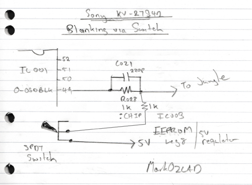
I did leave everything between the OSD chip and the jungle chip, with a toggle switch on blanking so I can still access the menu. I soldered RGB (with the cap and resister to ground) directly to the jungle on pins 34 (red), 35 (green), and 36 (blue), and sync to the board where the composite jack's leg goes. Is there a better place to inject the sync signal than composite for me? And is leaving the OSD connected to the RGB pins on the jungle causing the interference?
Does anyone have any recommendations? And is the banding due to sync issues? Sorry, I don't have a good pic of the smearing, it's hard to take pictures of a CRT without a bunch of scan lines in it
Jungle LA7612N pinout:
Banding:
Before mounting in the cabinet:
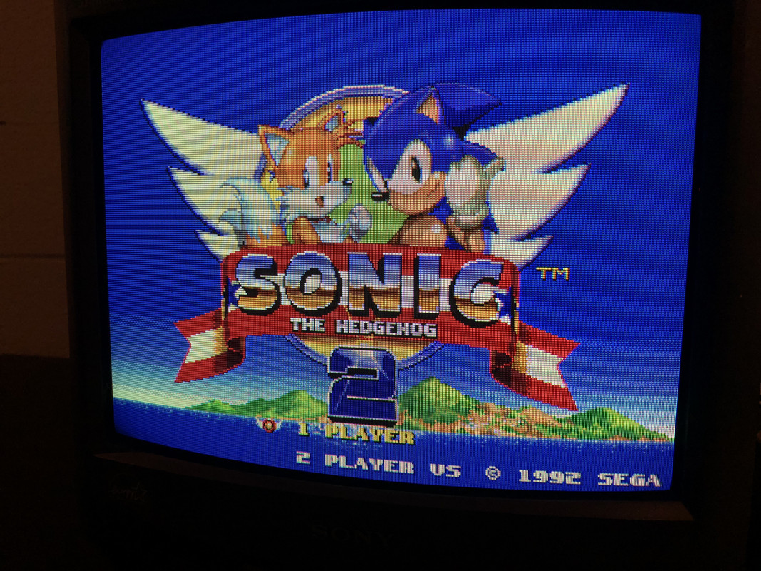
And a picture of the TV running mounted in my MVS cab
Service manual (close to mine, but my board layout is slightly different and missing several things):
https://www.electronica-pt.com/esquema/ ... 203-17330/
It does, interestingly, have the whole built-in TV guide, complete with an ARM SOC, RAM, and all on another board. But it doesn't have the connector for S-Video, the associated comb filter circuit or IC for it, or the PIP board socket

Last of all, thank you everyone for sharing your setups and wisdom. I couldn't have done this without this forum!


