He said he got it working with composite but it's not working for me and he said he was only able to get it to show a picture straight to his TV.
Will it work via composite?
Spoiler
Plug the cable into the console and take out your multimeter. Measure the resistance between the CS# pad and pin 20 of the SCART cable. There's probably a resistor in there.leonk wrote:
The cable was built by that lady on eBay. It only has 220 ohm caps on RGB lines. Cable works great with snes/n64 using sync generated by those consoles, black screen/audio only on Nesrgb. I've had multiple customers report this issue, and this is a result of my finding.
Opening J8 fixes the issue.
The installation looks fine. It should work with composite video if you use an NTSC version A/V cable (the PAL one is different).Smashbro29 wrote:I bought a premodded AV Famicom.
He said he got it working with composite but it's not working for me and he said he was only able to get it to show a picture straight to his TV.
Will it work via composite?
Yes, Luma is affected too. There is an upgrade mod. Please send me an email and I'll give you the details.keropi wrote:My boards have "NESRGB T.W. 2013" silkscreened so they are old... I am using LUMA as sync , is this affected as well?viletim wrote: The early version, the one marked only NESRGB on the silkscreen with no number after it, has a bad sync separator circuit. You should use PPUV video signal for sync in this case.
Could one "upgrade" the sync seperator on these old boards or does it require a huge change? (I did replace the srams back then so this kind of soldering is no problem for me...) Maybe I can make some small board with the new sync stuff and just add it to the NESRGB like the component addon?
I tried the composite cable I used to use for N64/SNES, official Nintendo NTSC. Worked with my SNES and N64 perfectly but I put it into both the mini and multiple TVs directly with the AV Famicom and I got nothing. My games are clean as a whistle but I was told I'd get a blank signal even if no game was inserted and both the TVs and the mini reported no input.viletim wrote:
The installation looks fine. It should work with composite video if you use an NTSC version A/V cable (the PAL one is different).
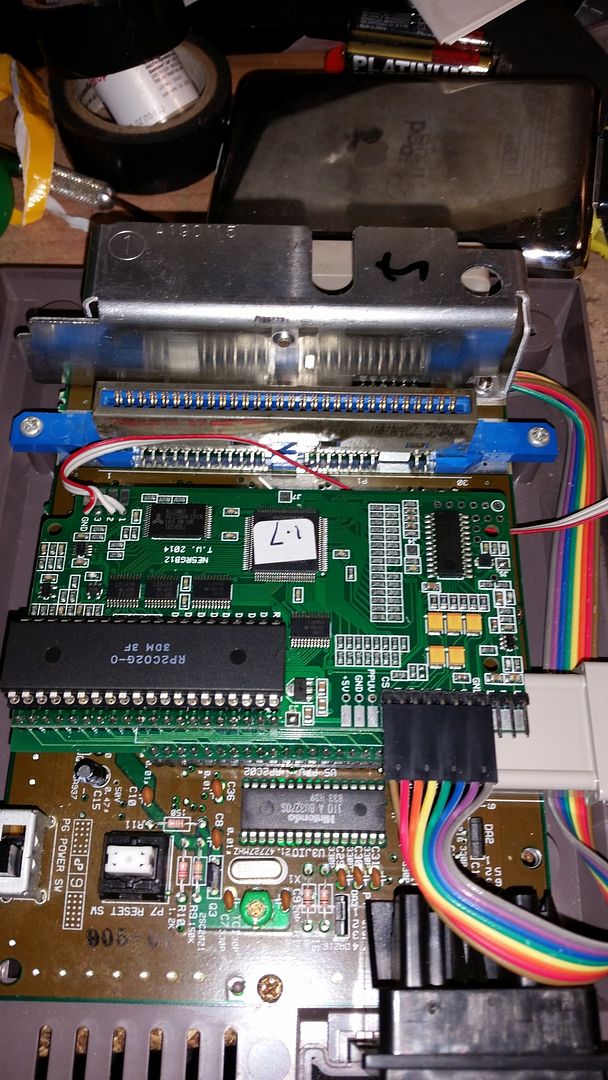
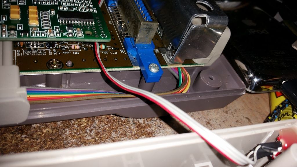
1) My RGB setup is temporarily down but he assures me all 3 workleonk wrote:The composite video on that install is the green wire. As you can see, he cut the original pin 21 / amplified composite video (last picture) and is using the composite video from the NESRGB. If you use standard SNES/N64 composite video cable (yellow/red/white), it should work for you.
The install is "OK" but I would have done a few things differently:
1) BIG issue - The palette switch. He seems to have installed a 2 way switch rather than 3 way. You select between enhanced or PC10. There's no way for you to select the real NES/Famicom palette (short between pin 3 and GND)!!! If using only 2 way, I would have done original/enhanced and dumped the PC10.
2) The NESRGB is not secured in any way to the NES PCB. Gametech.us has a good suggestion of using glue stick posts. I've done that with great success for my customers as well.
3) No LED mod
4) Q1 (the old composite video amp) is still there! It's recommended to be removed to avoid Everdrive N8 issues
Oh, so it simply doesn't work at all? No sound or video? The installation looks typical from the photos, but there is obviously something wrong. Test your power supply and AV cable if you can. Otherwise, this matter should be taken up with whoever sold it to you.Smashbro29 wrote:I tried the composite cable I used to use for N64/SNES, official Nintendo NTSC. Worked with my SNES and N64 perfectly but I put it into both the mini and multiple TVs directly with the AV Famicom and I got nothing. My games are clean as a whistle but I was told I'd get a blank signal even if no game was inserted and both the TVs and the mini reported no input.viletim wrote:
The installation looks fine. It should work with composite video if you use an NTSC version A/V cable (the PAL one is different).
1) My RGB setup is temporarily down but he assures me all 3 work
leonk wrote:Tim, I can now confirm that the XRGB mini with latest firmware (2.00a) does not work with the NESRGB 1.4 with CSYNC set to 75ohm. It works great with TTL setting. There are no resistors/caps in SCART/RGB cable for sync wire.
I think the installation instructions be updated to reflect this finding.
No, you misunderstand.viletim wrote:Oh, so it simply doesn't work at all? No sound or video? The installation looks typical from the photos, but there is obviously something wrong. Test your power supply and AV cable if you can. Otherwise, this matter should be taken up with whoever sold it to you.Smashbro29 wrote:I tried the composite cable I used to use for N64/SNES, official Nintendo NTSC. Worked with my SNES and N64 perfectly but I put it into both the mini and multiple TVs directly with the AV Famicom and I got nothing. My games are clean as a whistle but I was told I'd get a blank signal even if no game was inserted and both the TVs and the mini reported no input.viletim wrote:
The installation looks fine. It should work with composite video if you use an NTSC version A/V cable (the PAL one is different).
1) My RGB setup is temporarily down but he assures me all 3 work
I've got a Hakko FX-888D, which seems to have a reasonable amount of power. It's a 70W soldering iron with a max temperature of 480c. I wanted to upgrade from my el-cheapo noname soldering iron (which cost like $20 USD), so it looked like a good upgrade. I would think that the thermal capacity of the iron would be more important than the max temperature, though...kamiboy wrote:Several of the NES PPU legs are connected to GND which due to their surface area act as large heat sinks, so melting the solder around those legs can be a nightmare unless you have a very hot iron.
couldn't sleep, so tried; can only get some red glitches. PPU is indeed fried. Let's hope there's nothing more and that I can easily find one...nihonmasa wrote:e with the board itself (unfortunately unlikely) .
If you could desolder the NES RF box then your iron should have the thermal capacity to desolder the pins that are attached to the ground plane without too much of a problem.Guspaz wrote:As an NESRGB is something that I've been considering doing, what specifically about the desoldering gave you difficulty?
Based on the relatively limited desoldering that I've done in the past, my attempt to desolder would include:
1) Add a lot of solder to each pin on the bottom of the motherboard
2) Heat up each solder joint and hit it with the solder pump
3) Wiggle each pin a bit to break residual solder
This approach has worked for me before, most recently to replace the analog stick pot on a gamecube controller, but that was only 10 pins compared to the 40 pins on the PPU. Is there something different about the PPU that would break my normal approach?
One potential good thing is that I do have a junk NES motherboard that I can try it on before I try it on the "real" thing. The junk board was perfectly fine, but I desoldered the RF box (and accidentally crushed a ceramic cap) to use in a different project, but it does give me a motherboard to experiment on so that if I mess up I've not destroyed my real NES. Or a potential spare CPU/PPU if that part goes wrong.
EDIT: Desoldering the NES RF box was a pain, it took hours because of the massive tabs that are soldered in. Doing the pins themselves was easy, but for the giant tabs attached to the ground plane, it was melt one joint, pry a bit with a screwdriver, let cool, melt next join, pry a bit with the screwdriver, let cool... Repeat for several hours.
As both of you mention, thermal capacity/tip mass is more important than actual temperature limits. I have a Pace desoldering iron which I suspect the Hakko is similar to, though packaged differently since it's not a self-contained gun. In an old VHS tape that came with the tool when i got it years ago, they recommended the technique of desoldering alternate pins around the chip and then making a second pass to do the others; in that way you don't heat the same concentrated area for as long a period of time. Sounded like a good idea and I've always used the technique; whether it actually does anything or not I don't think it can hurt. (A sort of ironic comment coming from me I suppose lol.)darcagn wrote:If you could desolder the NES RF box then your iron should have the thermal capacity to desolder the pins that are attached to the ground plane without too much of a problem.Guspaz wrote:As an NESRGB is something that I've been considering doing, what specifically about the desoldering gave you difficulty?
Based on the relatively limited desoldering that I've done in the past, my attempt to desolder would include:
1) Add a lot of solder to each pin on the bottom of the motherboard
2) Heat up each solder joint and hit it with the solder pump
3) Wiggle each pin a bit to break residual solder
This approach has worked for me before, most recently to replace the analog stick pot on a gamecube controller, but that was only 10 pins compared to the 40 pins on the PPU. Is there something different about the PPU that would break my normal approach?
One potential good thing is that I do have a junk NES motherboard that I can try it on before I try it on the "real" thing. The junk board was perfectly fine, but I desoldered the RF box (and accidentally crushed a ceramic cap) to use in a different project, but it does give me a motherboard to experiment on so that if I mess up I've not destroyed my real NES. Or a potential spare CPU/PPU if that part goes wrong.
EDIT: Desoldering the NES RF box was a pain, it took hours because of the massive tabs that are soldered in. Doing the pins themselves was easy, but for the giant tabs attached to the ground plane, it was melt one joint, pry a bit with a screwdriver, let cool, melt next join, pry a bit with the screwdriver, let cool... Repeat for several hours.
I highly, highly recommend a desoldering gun (like the Hakko 808 or Hakko FR-300). It makes the work a piece of cake. However, I have desoldered the NES PPU (for PC10 RGB PPU installs and NESRGB installs) and CPU (for CopyNES installs) with just a Radio Shack shit desoldering iron w/ pump, before I owned my Hakko 808. It was basically a tedious task of what you said above: add solder, use pump, wiggle pin until it's free; repeat. Use caution to make sure you don't heat up the PPU too much and fry it (i.e. be patient!). Also, make sure you know how to repair traces in case you damage a trace or via when removing the PPU.
You can do the job quite well with just a generic Radio-Shack de-soldering iron (with bulb pump).Guspaz wrote: Desoldering the NES RF box was a pain, it took hours because of the massive tabs that are soldered in. Doing the pins themselves was easy, but for the giant tabs attached to the ground plane, it was melt one joint, pry a bit with a screwdriver, let cool, melt next join, pry a bit with the screwdriver, let cool... Repeat for several hours.

Voultar pulled the PPU out of that system with vice grips, he told me so.Voultar wrote:You can do the job quite well with just a generic Radio-Shack de-soldering iron (with bulb pump).Guspaz wrote: Desoldering the NES RF box was a pain, it took hours because of the massive tabs that are soldered in. Doing the pins themselves was easy, but for the giant tabs attached to the ground plane, it was melt one joint, pry a bit with a screwdriver, let cool, melt next join, pry a bit with the screwdriver, let cool... Repeat for several hours.
I made a little quick and dirty (horribly edited) video to outline good practice when removing these chips.
I didn't speed up the desoldering process, the video is for the most part raw.
https://www.youtube.com/watch?v=_PJQLRuB1n8
Improper desoldering can and will result in several lifted via's and traces. I've had SEVERAL sent to me that required extensive trace repair. If it doesn't want to come out with very light force, don't pull it.
oh yeahVoultar wrote:No, I didn't..
I said channel-locks, not vice-grips..
You normally use an air hammer when removing PPUs, right?Voultar wrote:No, I didn't..
I said channel-locks, not vice-grips..

It's a PVM-1910 and I'm using composite video for sync. I've been told to get a video cable wired for csync and hook up CS#, so I'm going to give that a try.Skips wrote:What model is the PVM and are you using composite sync, composite video for sync, Luma for sync, or PPUV for sync?


