NESRGB board available now

The place for all discussion on gaming hardware
User avatar
holaplaneta
Posts: 89
Joined: Fri Jul 27, 2012 1:30 am

Re: NESRGB board available now

Post by holaplaneta »

leonk wrote:My post above is what I do, and I play Lagrange point, and it sounds perfect.

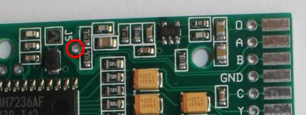
Yes, you will need to do the full audio in/out. The NESRGB mixes the EXP in from that hole next to J5. 47K ohm is the correct size for real famicom carts.
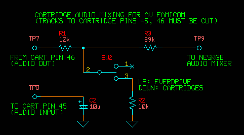
I agree with user Ripthorn, I have read on most posts that a 1.2k resistor is the one to go on the NES Top Loader. As him, I´m a Noob that does not know how to read schematics. I saw Tim´s schematics for the A/V Famicom and noticed that the sum of the R1 Resistor is 10k plus the value of the R3 Resistor at 39k in total are 49k, so I suppose the 47k resistor is the correct one since it is the closest in value to 49k. Is this correct?
Image


But then again, the NES Top Loader even when similar to the A/V Famicom has different steps, like for example needing to cut tracks to cartridge pins 45 and 46, right?, which is not needed for the Top Loader.

On the other hand, if I do not want to have a switch (as in SW2 with the R2 resistor at 10k) as on Tim´s schematics for the A/V Famicom and I just want to do the following on my NES Top Loader:

Run Pin 51 -> 47K resistor -> Audio Mixing hole on the NESRGB which is circled in this image next to the J5.
(Older revisions of the NESRGB did not have this hole, and you had to solder to the 2 transistors next to it, is that right?)

Image


Would it be all right? Is this the correct configuration for the Expansion Audio Mod on the NES Top Loader?
What about all those posts saying that a 1.2k Resistor should be used instead? Are they gaining more volume at the expense of less balance or something like that? Is the 47k resistor the correct one for both the A/V Famicom and the NES Top Loader Expanded Audio Mods?

Sorry for asking so many questions, but since Tim´s schematics are more complex than my description and are specifically for the A/V Famicom, I prefer to ask.

Thanks for your help
Last edited by holaplaneta on Wed May 25, 2016 5:59 am, edited 2 times in total.
Ripthorn
Posts: 145
Joined: Thu Nov 27, 2014 8:36 pm
Location: Hellhole

Re: NESRGB board available now

Post by Ripthorn »

Sorry guys, I could not find :oops:
mvsfan wrote:right under the two audio pins. you want to attach to the end of the resistor closest to the cpu.
leonk wrote:Just look at the board. You can see the wires from pin 1/2 go to them. They're right next to the CPU.
Did you mean traces? I found just one trace leaving cpu pin 1 but nothing on pin 2, maybe is hidden? I marked on the picture below the solder points that I think are correct, can you confirm?
Imageimg host

Have you played other games with expansion audio besides Lagrange Point? LP was one of the games I played in an unmoded AV Fami and the audio seems fine for me, different from Castlevania 3 JP that I could not hear the whip's sfx.
Einzelherz wrote:I'm considering an Everdrive N8 but I've got a question about expansion audio. When I installed my NESRGB, I setup the audio with a 100k resistor (iirc) and it sounds great on the one cartridge I have that uses it, Just Breed. I've read in this thread that the Everdrive expansion audio volume is lower.

Will I have to choose between real carts and the flash cart for resistor size or is there a way to get them both to play well?
Everdrive N8 has an option to increase the expansion audio volume, I recommend you look at this before anything.
User avatar
holaplaneta
Posts: 89
Joined: Fri Jul 27, 2012 1:30 am

Re: NESRGB board available now

Post by holaplaneta »

As read here: http://nintendopowerwhentheygotitright. ... oodie.html

"To obtain expansion sound on a Front Loader NES, you will need to solder a 47K resistor from pin 3 to pin 9 of the expansion connector. To obtain expansion sound on a Top Loader, you will need to solder a wire connecting pins 51 and 54 in the PowerPak. Next you will need to solder a 1.2K resistor between pin 51 and the audio out pin on the NES PCB. See here for details : http://forums.nesdev.com/viewtopic.php? ... sion+audio"

And here: http://nerdlypleasures.blogspot.mx/2014 ... ences.html

"The NES top loader does not connect the lockout chip pins and does not physically have pins for what would be pins 18, 19, 54 and 55. The Everdrive N8 and NES PowerPak use pin 54. One of the remaining pins (pin 51 has been suggested) can be connected with a 1.2K resistor and the audio output point."

"The NES (frontloader) expansion port has all the functionality of the Famicom Expansion port and much more... The expansion port can be used to mix audio from Famicom cartridges with the internal NES sound by connecting two pins (pin 3 and typically pin 9) with a 47K resistor. The expansion pin must also be connected on the cartridge converter for real Famicom cartridges."
____
leonk wrote:My post above is what I do, and I play Lagrange point, and it sounds perfect.

Yes, you will need to do the full audio in/out. The NESRGB mixes the EXP in from that hole next to J5. 47K ohm is the correct size for real famicom carts.
So now I´m even more confused as why user leonk has the TopLoader + NESRGB modded with a 47k resistor and says he has good results... I´m aware he plays with real Famicom carts, so maybe that is why 47k is enough for him. But when he puts an Everdrive or real American NES cart, is the volume just lower and he just turns it up on his tv set?

I read on another forum a post by user Bregalad that stated: "I noticed the audio in the toploader is not amplified at all, it just comes straight out from the 2A03, through a set of resistors and capacitors. That's why I have to make the volume louder to compensate for that." and "In the Frontloader mod you also just had to add a resistor so I just inspired myself from that. The only difference is that the audio is not amplified so you need a different (smaller) value for the resistor. I tried different values unless I figured out that 1.2k was the one who sounded the most right with my powerpak. A lower value would make external audio louder and a higher value would make it quieter. "

So, what is the correct resistor value for the Top Loader NES + NESRGB by Tim´s standards (using the Audio Mixing hole on the NESRGB board) if I want to play games with an Everdrive N8 NES or Powerpak and real american NES carts? 47k or 1.2k?

Thanks! :)
leonk
Posts: 1080
Joined: Sun Mar 13, 2011 9:29 pm
Location: Toronto, Canada

Re: NESRGB board available now

Post by leonk »

Some answers to the above comments / questions:

1) I see the 2 resistors right there in the picture!!! They are R9 and R10. Connect the wires to the left side (closer to CPU). (this is for audio from CPU)

2) 47K ohm resistor is the correct resistor to play expanded audio famicom games on real NES. The resistor has no effect on the native audio! The NESRGB mixes the audio generated by the NES CPU together with audio generated by the cart. The 47K resistor attenuates the output from the cart to the same level as that coming from the CPU. I tested this with real lagrange point, real castlevania, real FDS games and my real copy of Mr Gimmick! as well as NES reproductions of Mr Gimmick using the Yamaha sound synthesizer.

It doesn't matter if you use Top Loader or Front Loader. You intercept the audio from the CPU directly with no extra passive components between NES CPU and NESRGB.
User avatar
holaplaneta
Posts: 89
Joined: Fri Jul 27, 2012 1:30 am

Re: NESRGB board available now

Post by holaplaneta »

Thank you for answering leonk!

So the suggestion of using a 1.2k resistor on the Top Loader instead of the 47k one, comes from wanting to play real american NES carts that came with expansion audio and roms with expansion audio in flash carts such as the Everdrive N8 or the Powerpak instead of original Famicom carts with expansion audio?
leonk
Posts: 1080
Joined: Sun Mar 13, 2011 9:29 pm
Location: Toronto, Canada

Re: NESRGB board available now

Post by leonk »

holaplaneta wrote:Thank you for answering leonk!

So the suggestion of using a 1.2k resistor on the Top Loader instead of the 47k one, comes from wanting to play real american NES carts that came with expansion audio and roms with expansion audio in flash carts such as the Everdrive N8 or the Powerpak instead of original Famicom carts with expansion audio?
Maybe. Keep in mind that:

- EXP audio support on PowerPak / Everdrive is not as good as real carts
- EXP audio only existed on Famicom - not NES!
- EXP audio output from PowerPak / Everdrive is much lower than real cart - hence why it might need 1.2k instead of 47K

Personally, I only play real carts. So the famicom carts (via 60 to 72 pin converter) require the 47k.
User avatar
Einzelherz
Posts: 1279
Joined: Wed Apr 09, 2014 2:09 am

Re: NESRGB board available now

Post by Einzelherz »

Can anyone who has used the expansion audio on the Everdrive chime in regarding the supposed volume increase/decrease compensation option?
Ripthorn
Posts: 145
Joined: Thu Nov 27, 2014 8:36 pm
Location: Hellhole

Re: NESRGB board available now

Post by Ripthorn »

leonk wrote:Some answers to the above comments / questions:

1) I see the 2 resistors right there in the picture!!! They are R9 and R10. Connect the wires to the left side (closer to CPU). (this is for audio from CPU)

2) 47K ohm resistor is the correct resistor to play expanded audio famicom games on real NES. The resistor has no effect on the native audio! The NESRGB mixes the audio generated by the NES CPU together with audio generated by the cart. The 47K resistor attenuates the output from the cart to the same level as that coming from the CPU. I tested this with real lagrange point, real castlevania, real FDS games and my real copy of Mr Gimmick! as well as NES reproductions of Mr Gimmick using the Yamaha sound synthesizer.

It doesn't matter if you use Top Loader or Front Loader. You intercept the audio from the CPU directly with no extra passive components between NES CPU and NESRGB.
Well, that's why I did not find, resistors is next to the PPU, not CPU :P
R9 is CPU pin 1 and R10 pin 2?
Is the same thing on AV Famicom? I saw the R9 and R10 resistors but is in a different location.

Here is the summary:

NES Top Loader
  • install 47k ohm resistor on EXP input on NESRGB
    run a wire from pin 51 to this resistor
    run a wire from resistor R9 to Audio Input A
    run a wire from resistor R10 to Audio Input B
    modify your 60 to 72 pin converter - add wire from pin 54 to pin 51
AV Famicom
  • install 47k ohm resistor on EXP input on NESRGB
    cut the traces from pin 45 and 46
    ground pin 45 with a 10uf cap (Optional? I found a post from Vigomortis and he did not bother to ground pin 45)
    run a wire from pin 46 to this resistor
    run a wire from resistor R9 to Audio Input A
    run a wire from resistor R10 to Audio Input B
The Famicom part is correct? I'm not sure about ground pin 45.
leonk
Posts: 1080
Joined: Sun Mar 13, 2011 9:29 pm
Location: Toronto, Canada

Re: NESRGB board available now

Post by leonk »

arg!!! i made a mistake!! the 2 resistors i told you are wrong!! the correct ones are circled already in the picture!! (the pcb is upside down relative to how I normally see it!!)
leonk
Posts: 1080
Joined: Sun Mar 13, 2011 9:29 pm
Location: Toronto, Canada

Re: NESRGB board available now

Post by leonk »

I dont bother with doing anything with audio on the famicom AV. It handles exp audio correctly and I never heard any noise / audio problems with the stock circuit. Only NES systems need the exp audio mod because they dont have it.
Ripthorn
Posts: 145
Joined: Thu Nov 27, 2014 8:36 pm
Location: Hellhole

Re: NESRGB board available now

Post by Ripthorn »

leonk wrote:arg!!! i made a mistake!! the 2 resistors i told you are wrong!! the correct ones are circled already in the picture!! (the pcb is upside down relative to how I normally see it!!)
Ok, thanks. Sorry about the picture :mrgreen:
leonk wrote:I dont bother with doing anything with audio on the famicom AV. It handles exp audio correctly and I never heard any noise / audio problems with the stock circuit. Only NES systems need the exp audio mod because they dont have it.
The problem with AV Famicom expansion audio is the volume, too loud. :|
leonk
Posts: 1080
Joined: Sun Mar 13, 2011 9:29 pm
Location: Toronto, Canada

Re: NESRGB board available now

Post by leonk »

Ripthorn wrote:The problem with AV Famicom expansion audio is the volume, too loud. :|
I didn't find that to be the case with carts I tried. Remember, this console was made by Nintendo for use with Famicom carts in Japan. As far as I'm concerned, the Famicom AV is the best 8 bit console Nintendo made. I leave the audio path as is when I do NESRGB mods on it.

... and if it is too loud, then that would then be perfect for PowerPak / EverDrive. :)
User avatar
FBX
Posts: 2347
Joined: Wed Feb 18, 2015 10:18 am
Location: DFW area, Texas
Contact:

Re: NESRGB board available now

Post by FBX »

Einzelherz wrote:Can anyone who has used the expansion audio on the Everdrive chime in regarding the supposed volume increase/decrease compensation option?
I had based my resistor mod on the default Everdrive setting, which was high volume on mine. What I did was get an assortment of various resistor values and tested each one until the extra tracks on Castelvania III sounded balanced.

In the end though, Everdrive extra sound emulation is pretty shoddy. In that regard, I was a little disappointed it wasn't a viable alternative to getting a Famicom.
User avatar
Einzelherz
Posts: 1279
Joined: Wed Apr 09, 2014 2:09 am

Re: NESRGB board available now

Post by Einzelherz »

FBX wrote:
Einzelherz wrote:Can anyone who has used the expansion audio on the Everdrive chime in regarding the supposed volume increase/decrease compensation option?
I had based my resistor mod on the default Everdrive setting, which was high volume on mine. What I did was get an assortment of various resistor values and tested each one until the extra tracks on Castelvania III sounded balanced.

In the end though, Everdrive extra sound emulation is pretty shoddy. In that regard, I was a little disappointed it wasn't a viable alternative to getting a Famicom.
Well the expansion audio is secondary to the fact that several more rare Famicom games are getting too pricey. Should have bought Akumajo Densetsu and Lagrange Point years ago :-)
djdavedoc
Posts: 14
Joined: Sun Jan 26, 2014 5:12 pm

Re: NESRGB board available now

Post by djdavedoc »

Hi Guys, I have an RGB Modded Original Famicom (NESRGB from Tim Worthington). All seems ok except that during some games (particularly noticeable with my multicart's Menu Screen) I get some lines going down the screen from top to bottom. Any ideas on the cause of this? I have tried it using a couple of different TV's and the same effect still applies. I have even tried different PSU's (SEGA Mega Drive Model 1 and some generic 9v 2A PSU's) and the effect is the same.

I have attached a picture to try and show you what I am talking about. Any advice would be greatly appreciated.

Image
leonk
Posts: 1080
Joined: Sun Mar 13, 2011 9:29 pm
Location: Toronto, Canada

Re: NESRGB board available now

Post by leonk »

This might be the same issue gametech us (Jason) found with his NESRGB installs .. the composite video amp needs to be removed. It creates feedback onto pin 21 of the PPU.
djdavedoc
Posts: 14
Joined: Sun Jan 26, 2014 5:12 pm

Re: NESRGB board available now

Post by djdavedoc »

Hi Thanks for the reply. Where is the Composite Amp and how do I go about removing it?
leonk
Posts: 1080
Joined: Sun Mar 13, 2011 9:29 pm
Location: Toronto, Canada

Re: NESRGB board available now

Post by leonk »

On the front loader, it's called Q1 / A939. It's between the PPU and the blue power connector.
User avatar
Guspaz
Posts: 3148
Joined: Tue Oct 06, 2015 7:37 pm
Location: Montréal, Canada

Re: NESRGB board available now

Post by Guspaz »

I built the NESRGB SCART connector adapter kit tonight. The instructions didn't have me doing anything with the SCART shield (pin 21, the outer metal shell), it's not connected to anything... Is that expected? Shouldn't it be connected to ground?
djdavedoc
Posts: 14
Joined: Sun Jan 26, 2014 5:12 pm

Re: NESRGB board available now

Post by djdavedoc »

Hi leonk, where would I find this on my regular Famicom that has NESRGB installed?

I have heard people saying about lifting Pin 21 of the PPU, is that something I could do and then put the PPU back into the NESRGB board?
User avatar
ApolloBoy
Posts: 938
Joined: Sat Jan 28, 2012 7:17 pm
Location: San Jose, CA

Re: NESRGB board available now

Post by ApolloBoy »

The video transistor is also labeled as "Q1" on the Famicom motherboard; it's a 2SA937 transistor located right next to the PPU.
roquer.jordi
Posts: 3
Joined: Sat May 09, 2015 10:09 pm

Re: NESRGB board available now

Post by roquer.jordi »

Hi, I recently purchased a AV-Famicom with Tim Worthington NESRGB mod installed and I dont know why but image has blinking pixels and pixels with wrong colors. I thought it was a problem with third party RGB cable but I tried connecting to my LCT TV with a original PAL Gamecube scart cable and same problem. Also it happens with any game I try, some look better but always glitches appears ¿Anyone knows something about this problem? I'm a bit desesperated and I will appreciatte any help.

Video showing the problem in Tetris (problem starts in 00:15)

https://youtu.be/TyH6zB4O7GY

Thanks!
User avatar
Guspaz
Posts: 3148
Joined: Tue Oct 06, 2015 7:37 pm
Location: Montréal, Canada

Re: NESRGB board available now

Post by Guspaz »

I finished my NESRGB install today, and it seems to be working well. I was kind of surprised, actually, that I hadn't goofed anything up, considering this is the most complex soldering project that I've ever done, by like an order of magnitude. I was half expecting the PPU to be fried, for example :)

This was obviously my first NESRGB install, so it probably took 10-12 hours of work over the course of four days. Here's some shots:

NESRGB itself: http://i.imgur.com/3NjzPka.jpg (any advice on how to avoid solder following the iron off the pad and making a little point? Use less solder maybe?)

Ports on the back: http://i.imgur.com/QV61oJG.jpg

My experience, and please note that the following are coming from the perspective of somebody with no experience doing this stuff, so stuff that might seem obvious to you may not have been obvious to me.
  • Desoldering the PPU is really hard with nothing but a soldering iron and desolder braid. A solder sucker didn't seem to do any good (the tip is too wide to fit over individual pins of the PPU), and my desoldering iron crapped out right at the start of the project. I bought the (very cheap) desoldering iron for this project, practiced on a broken NES motherboard by removing the CPU and PPU without too much difficulty, and it seems like ~80 joints was all it was good for. I tried it on this one and it just would not get hot enough, even after cleaning the tip with high-grit sandpaper as a last resort. So I did it the very long and very hard way. I was worried that the PPU might be fried from so much re-heating from the slow manual approach, so I actually used the PPU from the practice board, which worked fine. I feel like having a desolder gun like the Hako 808 would make this entire project enormously easier, but they're too expensive to buy for a one-off project: this was my own console, I don't plan to mod other people's stuff.
  • The previous point does mean I'm using an "E" PPU with a "G" CPU, but that doesn't seem to matter?
  • The PPU sits in the NESRGB on an angle, since one row of the pin headers push up against one side underneath. It doesn't look like there is any possible way that it could *not* be like this, but it wasn't mentioned in any of the instructions, so it was a bit worrying. Doesn't seem to cause any problems, though it did make soldering in the PPU slightly harder, since the pins were nearly flush with the other side of the holes.
  • Also missing in the instructions: the wiring guide says to wire Audio A and Audio B to CPU pins 1 and 2, but provides no information about which pins on the CPU are 1 and 2. Had to google a pinout of the CPU for that. A simple mention of "The CPU pins that connect to R4 and R3" would have been useful.
  • All I had was one colour of wire (26 AWG kynar silver-plated solid-core copper), so I used a silver sharpie to draw little bands on the wires to number them, making sure that there were no duplicate wire numbers on any given connector. It did rub off a bit while soldering the wires down, but overall this worked *great* and made soldering the right wires *way* easier. It was a bit time consuming to mark them all with the sharpie, but it was worth it. However, simply getting six different colours of wire, while expensive ($15 to $35 per spool depending on colour), would have saved a bunch of time.
  • I cut little rings of heatshrink and stuck two of them on each set of wires to bundle them up. Didn't shrink the tubing, just left it as-is: I saw a suggestion to bundle wires somewhere, and this did make wrangling the wires a lot easier. I believe it was 1mm for the pairs of wires, and 2mm for the 6-wire video bundle.
  • I ended up deciding to just use the standard NESRGB video connector, since it's simpler to install and I didn't want to try to overreach on my first such project. Imperial measurements for the hole sizes would be good, though: Canada might be a metric country, but all drill measurements seem to be imperial, and figuring out what step drill bits to buy was tough. IIRC the video connector ended up being 15/32 inches, which is slightly smaller than the 12mm in the instructions, but the video connector is only 11.3mm.
  • Soldering the video connector board to the video connector was very difficult, since it's hard to get even a small soldering iron tip in to hit the joint on the middle pins. It's too bad the connector can't be soldered to the board and *then* mounted on the case. I feel like my solder joints on the board aren't as good as they should be, but they're good enough since there shouldn't really be any force applied to those joints. EDIT: Or maybe I should have just put the board on the connector a little bit, so that only the tip of the pin is sticking through, that would have made soldering easier, since the pins wouldn't block the iron from reaching other pins.
  • Soldering multiple wires to one pad (three in the case of ground, IIRC) was tough, I'm thinking I probably should have stripped a bit more off the wires and tried to twist them together, although that's really hard with solid-core wire. Or maybe I could have wrapped the bundle in kapton tape just before the stripped bits.
  • I guess I didn't use the right epoxy: I bought a BPA binary epoxy, and put it on last night, and let it cure for around 14 hours. The first time I plugged the mini-din in today, the epoxy seemed to fracture internally: http://i.imgur.com/lJuVT1L.jpg The surface still seems intact, so hopefully that's all that happens. I'm wondering if I should have tried hot glue or superglue instead?
  • I didn't bother with the palette switch, since I just want the natural palette for now. I just bridged the pads with a short loop of wire, and I can always install the switch in the future if I want it. Of course, it also means I can't turn the NESRGB off, so RGB is the only video output that I've got, but it's fine for now. I might throw some extra video connectors on there some day, though.
  • The quality of the 8-pin mini-DIN cable that comes with the NESRGB cable kit is complete shit. One connector is attached at like a 20 degree angle off straight, and the other connector moves around in the housing, with a bit of glue visible sticking out. Cables that you buy at the dollar store have better build quality than these, at least those don't seem like they might fall apart at any moment!

Overall, I'm quite happy, it was a lot of work, but it seems to have resulted in a relatively clean install, and it works, and I can take a bit of satisfaction in having done it myself. I wouldn't do another such project without a proper desoldering gun, though!
User avatar
ApolloBoy
Posts: 938
Joined: Sat Jan 28, 2012 7:17 pm
Location: San Jose, CA

Re: NESRGB board available now

Post by ApolloBoy »

Guspaz wrote: [*]I guess I didn't use the right epoxy: I bought a BPA binary epoxy, and put it on last night, and let it cure for around 14 hours. The first time I plugged the mini-din in today, the epoxy seemed to fracture internally: http://i.imgur.com/lJuVT1L.jpg The surface still seems intact, so hopefully that's all that happens. I'm wondering if I should have tried hot glue or superglue instead?!
I would just toss that connector entirely and use a proper panel-mount jack that mounts either with screws or a large nut. I hate seeing glue of any kind on video connectors and it just doesn't last.
User avatar
mickcris
Posts: 435
Joined: Tue Oct 08, 2013 12:43 am
Location: Texas, USA

Re: NESRGB board available now

Post by mickcris »

I've put connectors on with regular jb weld and it holds up just fine
http://www.jbweld.com/collections/epoxy ... -twin-tube
User avatar
Guspaz
Posts: 3148
Joined: Tue Oct 06, 2015 7:37 pm
Location: Montréal, Canada

Re: NESRGB board available now

Post by Guspaz »

The problem would be getting the connector back off. Despite the epoxy fracturing internally, most of it is still intact, so it's still firmly in place, and even if I did get the epoxy off, I'm not sure if desoldering the board off is even possible due to how hard it was to solder it in the first place. I guess that it would first have to completely come free of the epoxy, and then I'd need to cut it off, but I'm not sure there's even enough room to get a cutting tool in there.

I think I'll leave it as-is for now (maybe it'll be fine), and if it does eventually fail, it may be easier just to put connectors on a new bottom shell: I've got two spares. Then either use jb-weld or a panel-mount jack. Or maybe actually go for the 32-printed multi-out.
User avatar
Einzelherz
Posts: 1279
Joined: Wed Apr 09, 2014 2:09 am

Re: NESRGB board available now

Post by Einzelherz »

Despite that it took the majority of my install's time, I'm still really happy with my minidin 9 in place of the RFU port. It was very less than fun.

Guspaz, I believe you can rewire the composite line and audio feed to the standard side connectors pretty easily if you want a non rgb option.
User avatar
Guspaz
Posts: 3148
Joined: Tue Oct 06, 2015 7:37 pm
Location: Montréal, Canada

Re: NESRGB board available now

Post by Guspaz »

I can't see how you'd do that, without desoldering the whole RF box, unless you want to cut some traces on the motherboard and run the audio and video into the 5-pin connector that goes off the motherboard. But then you're going through the NES video amp, so I think you'd need to reduce the voltage on the video line. Resistors, I guess?
leonk
Posts: 1080
Joined: Sun Mar 13, 2011 9:29 pm
Location: Toronto, Canada

Re: NESRGB board available now

Post by leonk »

Guspaz wrote:I finished my NESRGB install today, and it seems to be working well. I was kind of surprised, actually, that I hadn't goofed anything up, considering this is the most complex soldering project that I've ever done, by like an order of magnitude. I was half expecting the PPU to be fried
Congrats! IF there's a will, there's a way. No one was born knowing this stuff. You stuff have to put in the effort, the time, and be willing to learn from your mistakes. Even after all these years, I still learn something new almost every day.
Guspaz wrote:any advice on how to avoid solder following the iron off the pad and making a little point? Use less solder maybe?)
I typically used strand wire and solder it the other way. It then folds under the NESRGB. I find it cleaner not to see the wire. 30ga solid core wire .. have it.. never liked it.
Guspaz wrote: The previous point does mean I'm using an "E" PPU with a "G" CPU, but that doesn't seem to matter?
Doesn't matter.
Guspaz wrote: The PPU sits in the NESRGB on an angle, since one row of the pin headers push up against one side underneath. It doesn't look like there is any possible way that it could *not* be like this, but it wasn't mentioned in any of the instructions, so it was a bit worrying. Doesn't seem to cause any problems, though it did make soldering in the PPU slightly harder, since the pins were nearly flush with the other side of the holes.
Very common with front loader installs. I typically trim the pins of the header to make the PPU more flush. I then balance the ppu in the holes as I tack a couple of pins. Looks cleaner, but there's only so much you can do. Top loader installs have the PPU socketed so this problem doesn't happen.
Guspaz wrote: All I had was one colour of wire (26 AWG kynar silver-plated solid-core copper), so I used a silver sharpie to draw little bands on the wires to number them, making sure that there were no duplicate wire numbers on any given connector. It did rub off a bit while soldering the wires down, but overall this worked *great* and made soldering the right wires *way* easier. It was a bit time consuming to mark them all with the sharpie, but it was worth it. However, simply getting six different colours of wire, while expensive ($15 to $35 per spool depending on colour), would have saved a bunch of time.
I got an electronic supply store near hear. They sell the rainbow ribbon cable for only $5 for 10 foot rolls. You could also have found an old IDE or Floppy ribbon cable and use that. Not only is it the better stranded cable, but the wires are ordered (as they are tried together in the ribbon).
Guspaz wrote:I ended up deciding to just use the standard NESRGB video connector, since it's simpler to install and I didn't want to try to overreach on my first such project.
So your console is now RGB only.
Guspaz wrote: Soldering the video connector board to the video connector was very difficult, since it's hard to get even a small soldering iron tip in to hit the joint on the middle pins.
Hahaha. I had the same problem for a customer who insisted on the XRGB port rather than Nintendo MultiAV port. I realized what the trick is to get it done. You cut the darn pins you already soldered with your snips! BANG! Easy to get to the middle pin!!
Guspaz wrote:Soldering multiple wires to one pad (three in the case of ground, IIRC) was tough
!?! You should never have a moment where you need to do that! Tim provided you with multiple ground points for a reason.
Guspaz wrote:I'm wondering if I should have tried hot glue or superglue instead?
That's what I ended up doing. The shell physically stops the connector from sliding in. You need to just fill the void between the PCB and shell to stop the connector from sliding out. Hot glue would suffice.

You never said how you're using it.. what is your video output?
User avatar
Guspaz
Posts: 3148
Joined: Tue Oct 06, 2015 7:37 pm
Location: Montréal, Canada

Re: NESRGB board available now

Post by Guspaz »

leonk wrote:I typically used strand wire and solder it the other way. It then folds under the NESRGB. I find it cleaner not to see the wire. 30ga solid core wire .. have it.. never liked it.
So you push it up through the hole from under? I can see how that would produce a cleaner install.
leonk wrote:I got an electronic supply store near hear. They sell the rainbow ribbon cable for only $5 for 10 foot rolls. You could also have found an old IDE or Floppy ribbon cable and use that. Not only is it the better stranded cable, but the wires are ordered (as they are tried together in the ribbon).
I know there are electronics supply stores in Montreal, but they're nowhere near here, so there's a disincentive in both transit fare and time to go visit them for one-off items. If I was going to do a lot of this sort of install, it'd probably be worth it. I can see one day doing a toploader, and maybe some extra work on this one (put the switch in, some more outputs, fix/replace the eventual failed video socket), but not in the near future.
leonk wrote:So your console is now RGB only.
Yes, particularly because I have no way to turn the thing off without the switch. This is not a problem as long as nobody else wants to use my NES. The kit did come with an s-video connector that I could add, though clearly I need to try jbweld instead of BPA epoxy. More likely, if I want more video connection options, I should look into the 3D-printed Multi-AV connector, since you can also get composite video and S-Video and component (via HDR cables) on a single connector. Might need to swap out the bottom shell to do that, though.
leonk wrote:Hahaha. I had the same problem for a customer who insisted on the XRGB port rather than Nintendo MultiAV port. I realized what the trick is to get it done. You cut the darn pins you already soldered with your snips! BANG! Easy to get to the middle pin!!
*slaps forehead* It's so obvious now that you say it. That would have made it so much easier! And if the epoxy gives way (and I suspect it eventually will, considering the crackling sounds I hear when plugging the cable in), that'll make it at least possible to attempt to desolder it and get it out without cutting a huge hole in the back of the NES.
leonk wrote:!?! You should never have a moment where you need to do that! Tim provided you with multiple ground points for a reason.
There were two pads that needed multiple cables, ground (one to power board, one to audio jack, one to video jack, optionally a fourth to the s-video jack) and +5V (one to the regulator, one to the video socket). I completely blanked on the second ground pad on the main output section, but I don't see how you can't avoid doubling up at least one of them, with two pads and three to four ground wires. Although in hindsight, you could put one on the pad and one through the hole, and avoid soldering two cables to any one spot.
leonk wrote:That's what I ended up doing. The shell physically stops the connector from sliding in. You need to just fill the void between the PCB and shell to stop the connector from sliding out. Hot glue would suffice.
I didn't think about completely filling that void with hot glue, I was still thinking along the lines of sealing the edge of the connector. If I filled that whole void with hot glue, I wouldn't even need to wait for the epoxy to fail, I could just put it in place right now and it would prevent any future movement...
leonk wrote:You never said how you're using it.. what is your video output?
The ultimate destination is a PVM 14L2, although I'll need an OSSC or Framemeister if I want to loop that (and all my other RGB consoles) to my projector (which serves as my TV).

In terms of the connection chain:
  • NESRGB 8-pin mini din socket
  • Falling apart mini din cable that came with the NESRGB (seriously, WTF? It looks like it was hand assembled, and the metal bits are barely attached to the plastic bits)
  • NESRGB mini-din/3.5mm audio to SCART adapter from the connector kit (the hardest part of which was cutting the darned scart shell)
  • Bandridge 5-port automatic SCART switcher
  • Wookiewin SCART-to-BNC breakout cable
  • PVM 14L2
Audio is going through a different chain after the SCART switch, I won't go into that.
Post Reply