NESRGB board available now
-
EmperorZelos
- Posts: 265
- Joined: Fri Jul 19, 2013 3:39 pm
Re: NESRGB board available now
How much effort and skills does it acctually take to do this if someon has some minor medium experience with soldering?
Re: NESRGB board available now
Desoldering the PPU is the main challenge. The rest is very basic soldering.EmperorZelos wrote:How much effort and skills does it acctually take to do this if someon has some minor medium experience with soldering?
-
Einzelherz

- Posts: 1279
- Joined: Wed Apr 09, 2014 2:09 am
Re: NESRGB board available now
How different is desoldering the PPU compared to pulling the ROM chips off of a cart (without destroying them)?
Re: NESRGB board available now
slightly more difficult .. there's a lot more copper heat sinks around the PPU which requires a bit more effort. Also, the PPU is 40 pin. ROMs are 32 at most.Einzelherz wrote:How different is desoldering the PPU compared to pulling the ROM chips off of a cart (without destroying them)?
-
rCadeGaming
- Posts: 242
- Joined: Mon Dec 05, 2011 12:04 am
Re: NESRGB board available now
Ok, sorry if this has already been asked. Big thread. Is there any benefit to upgrading batch 1 hardware to firmware 1.7? Batch 1 isn't listed as having any known bugs here:
http://etim.net.au/nesrgb/background_fault/
Is that totally accurate?
Are the later firmwares compatible with batch 1 hardware, given the change in RAM chips?
http://etim.net.au/nesrgb/background_fault/
Is that totally accurate?
Are the later firmwares compatible with batch 1 hardware, given the change in RAM chips?
My Analog A/V setup: http://shmups.system11.org/viewtopic.php?f=6&t=43992
Ultimate Shmup Stick! JLF mod: http://shmups.system11.org/viewtopic.php?f=6&t=41451
Ultimate Shmup Stick! JLF mod: http://shmups.system11.org/viewtopic.php?f=6&t=41451
-
EmperorZelos
- Posts: 265
- Joined: Fri Jul 19, 2013 3:39 pm
Re: NESRGB board available now
How long does it take to get the wretched PPU chip off if you got a semi-proper desoldering tool?
Re: NESRGB board available now
A wise man once said, if it ain't broke...rCadeGaming wrote:Ok, sorry if this has already been asked. Big thread. Is there any benefit to upgrading batch 1 hardware to firmware 1.7? Batch 1 isn't listed as having any known bugs here:
http://etim.net.au/nesrgb/background_fault/
Is that totally accurate?
Are the later firmwares compatible with batch 1 hardware, given the change in RAM chips?

Re: NESRGB board available now
I don't believe batch 1 suffers from any of the RAM timing bugs, but it definitely does suffer from some other bugs (the 14/16 bit addressing issue that affects the Castlevania II Bisqwit retranslation and perhaps others, Everdrive issues, etc.). If you have the means to upgrade, I would do it, but it's not that big of a deal.rCadeGaming wrote:Ok, sorry if this has already been asked. Big thread. Is there any benefit to upgrading batch 1 hardware to firmware 1.7? Batch 1 isn't listed as having any known bugs here:
http://etim.net.au/nesrgb/background_fault/
Is that totally accurate?
Are the later firmwares compatible with batch 1 hardware, given the change in RAM chips?
-
rCadeGaming
- Posts: 242
- Joined: Mon Dec 05, 2011 12:04 am
Re: NESRGB board available now
Thanks. I don't think I'll be using an Everdrive. Is there any issue with a normal US Simon's quest cart?
So no problems with 1.7 firmware on batch 1 hardware then?
So no problems with 1.7 firmware on batch 1 hardware then?
My Analog A/V setup: http://shmups.system11.org/viewtopic.php?f=6&t=43992
Ultimate Shmup Stick! JLF mod: http://shmups.system11.org/viewtopic.php?f=6&t=41451
Ultimate Shmup Stick! JLF mod: http://shmups.system11.org/viewtopic.php?f=6&t=41451
Re: NESRGB board available now
Nope.rCadeGaming wrote:Is there any issue with a normal US Simon's quest cart?
Nope no problems with that, you can install 1.7 on batch 1 hardware.rCadeGaming wrote:So no problems with 1.7 firmware on batch 1 hardware then?
-
rCadeGaming
- Posts: 242
- Joined: Mon Dec 05, 2011 12:04 am
Re: NESRGB board available now
Ok, thanks. I'll watch for any problems and try updating if I see anything.
My Analog A/V setup: http://shmups.system11.org/viewtopic.php?f=6&t=43992
Ultimate Shmup Stick! JLF mod: http://shmups.system11.org/viewtopic.php?f=6&t=41451
Ultimate Shmup Stick! JLF mod: http://shmups.system11.org/viewtopic.php?f=6&t=41451
Re: NESRGB board available now
It took me a couple hours. Mind you it had been years since I'd last desoldered a high-pin-count DIP from anything... But this was using a soldering iron and a piston-type solder sucker, plus desoldering braid for cleaning up little bits of solder left behind...EmperorZelos wrote:How long does it take to get the wretched PPU chip off if you got a semi-proper desoldering tool?
As leonk said, one of the problems is that some of the pins are connected to large copper areas that will sink a lot of heat, making it difficult to adequately melt the solder for a pin. Another challenge on the front-loader is that the expansion port is right next to the PPU, so it can be difficult to access some of the pins with the soldering iron.
If you heat one side of the board, and use suction on the other side after the solder is fully heated, that's pretty effective. The problem is that if just a little solder is left behind, it can still be enough to bind a pin. A useful trick in that case is, rather than trying to remove that last bit of solder, just try to free the pin from it. Heat up the solder to reflow it, and move the pin around (without heating it) as it cools. To check if a pin is free, give it a little nudge to see if you can move it around.
I'm currently trying to wrap up my first install. I put the panel-mount RGB and S-Video connectors in place and wired up the S-Video one. I also wasted a bunch of time disconnecting and opening up the RF modulator unit to see if I could gut the RF mod and put the S-Video port in there. Ultimately decided it was just best to leave that alone. Kinda screwed up a bit, put the S-Video connector too close to one of the screw posts... But it's not so close that I wasn't able to wire it up. Though now I need to make an S-Video cable with RCA jacks at one end so I can test it with my monitor...

Re: NESRGB board available now
I did my first NES with an bog standard electric solder pump and that was difficult enough and also time consuming, i wouldn't recommend anyone try using just a solder iron and a manual pump. The best bet is to get a electric solder pump station, I got one a few months back and is excellent can now remove a PPU chip within about 5-10 minutes depending on how difficult some of the pins want to be.EmperorZelos wrote:How long does it take to get the wretched PPU chip off if you got a semi-proper desoldering tool?

Re: NESRGB board available now
1. Yep, done.darcagn wrote:1. Make sure you get the AV Famicom adapter board when you purchase the kit.
2. The three capacitors on the R, G, and B output lines on the NESRGB should be removed, as the AV Famicom uses multiout cables and multiout SCART cables already have capacitors in them.
3. Decide if you want to use the stock audio circuit (no work necessary) or if you want the NESRGB audio circuit (will need stock audio disconnected, expansion audio hooked up to NESRGB board, and NESRGB board wired to the multiout pins).
2. Noted. I will be using an official Gamecube cable hooked up to the XRGB-Mini.
3. Well, is the NESRGB audio circuit improved or do they sound exactly the same? Any comparisons available?
Anyway, thanks
Re: NESRGB board available now
the nesrgb audio circuit is definately improved. i think the best way to describe it is that some games like sky shark sound somewhere in between a nes and a sega genesis with the nesrgb sound circuit.
Re: NESRGB board available now
Was mentioned above about disconnecting stock audio, i never did this, i solder audio A & B up from the NESRGB and then ran them to the 2 capacitors near the CPU chip and then solder the Audio O pad on the NES RGB to the a/v socket on the rear of the nesmvsfan wrote:the nesrgb audio circuit is definately improved. i think the best way to describe it is that some games like sky shark sound somewhere in between a nes and a sega genesis with the nesrgb sound circuit.
Re: NESRGB board available now
Official GameCube cable as in a PAL GameCube cable? If so, a PAL cable will be wired for 12V on pin 3, but pin 3 on the AV Famicom would be wired for c-sync (as NTSC multiouts have c-sync on pin 3 and PAL multiouts have 12V on pin 3). This actually shouldn't cause a problem with the XRGB, but could cause problems with other setups if you tried to use this on a different display, and I'd recommend using c-sync for sync to begin with anyway because it should eliminate any diagonal lines appearing on your picture. So I would recommend getting an NTSC-based multiout/SCART cable that is wired for c-sync.Shining wrote:2. Noted. I will be using an official Gamecube cable hooked up to the XRGB-Mini.
I haven't actually done an installation on anything other than a front loader. However, if you connect the NESRGB audio to the audio pin on the AV out port on an AV Famicom without disconnecting the stock audio, won't you be mixing the old audio and the new audio together?lettuce wrote:Was mentioned above about disconnecting stock audio, i never did this, i solder audio A & B up from the NESRGB and then ran them to the 2 capacitors near the CPU chip and then solder the Audio O pad on the NES RGB to the a/v socket on the rear of the nes
Re: NESRGB board available now
[citation needed]darcagn wrote:A PAL cable will be wired for 12V on pin 3, but pin 3 on the AV Famicom would be wired for c-sync (as NTSC multiouts have c-sync on pin 3 and PAL multiouts have 12V on pin 3).
I haven't checked mine, but I'm fairly sure the only pins connected to anything on an AV famicom are:
Audio L (connected to mono)
Audio R (connected to mono)
Composite video
GND.
Furthermore, 12V is an output pin (meaning it goes from the console to the receiver), and the only effect you get from not connecting it or connecting it to the wrong voltage, is that the picture might be shown in 16:9 instead of 4:3. Not exactly a show-stopper.
-
Einzelherz
- Posts: 1279
- Joined: Wed Apr 09, 2014 2:09 am
Re: NESRGB board available now
Aside from the copper making things a little different though, it sounds like if I have little problem pulling ROMs then a PPU won't be much worse so long as I'm careful.leonk wrote:slightly more difficult .. there's a lot more copper heat sinks around the PPU which requires a bit more effort. Also, the PPU is 40 pin. ROMs are 32 at most.Einzelherz wrote:How different is desoldering the PPU compared to pulling the ROM chips off of a cart (without destroying them)?
Re: NESRGB board available now
How does that conflict with what I posted? I don't own an AV Famicom but the pin 3 on an AV Famicom is likely not connected to anything since pin 3 is for RGB21's c-sync in NTSC-land or SCART's 12V in PAL-land, and the AV Famicom only does composite. When the AV Famicom is RGB-modded the modder will likely connect c-sync to pin 3. However, his PAL SCART cable is still wired for 12V on pin 3 so his display would be receiving c-sync on SCART pin 8. That is fine if it's going through an XRGB-mini adapter but as I said it "could cause problems with other setups"mufunyo wrote:[citation needed]darcagn wrote:A PAL cable will be wired for 12V on pin 3, but pin 3 on the AV Famicom would be wired for c-sync (as NTSC multiouts have c-sync on pin 3 and PAL multiouts have 12V on pin 3).
I haven't checked mine, but I'm fairly sure the only pins connected to anything on an AV famicom are:
Audio L (connected to mono)
Audio R (connected to mono)
Composite video
GND.
This is a problem that could be caused, no? I didn't say his TV would burst into flames or anything.mufunyo wrote:Furthermore, 12V is an output pin (meaning it goes from the console to the receiver), and the only effect you get from not connecting it or connecting it to the wrong voltage, is that the picture might be shown in 16:9 instead of 4:3. Not exactly a show-stopper.
-
EmperorZelos
- Posts: 265
- Joined: Fri Jul 19, 2013 3:39 pm
Re: NESRGB board available now
I do have a desoldering iron that heats and sucks the solderin away.lettuce wrote:I did my first NES with an bog standard electric solder pump and that was difficult enough and also time consuming, i wouldn't recommend anyone try using just a solder iron and a manual pump. The best bet is to get a electric solder pump station, I got one a few months back and is excellent can now remove a PPU chip within about 5-10 minutes depending on how difficult some of the pins want to be.EmperorZelos wrote:How long does it take to get the wretched PPU chip off if you got a semi-proper desoldering tool?
Re: NESRGB board available now
What line(s) need to be cut on the AV Famicom board in order to use audio from the NESRGB? Do people think that both standard an expansion audio sound better?

Re: NESRGB board available now
I've found using the NESRGB for audio on AV Famicom systems does not improve the sound quality over stock. Using the NESRGB for audio on US systems without adding expansion audio makes a huge improvement in sound quality.daskrabs wrote:What line(s) need to be cut on the AV Famicom board in order to use audio from the NESRGB? Do people think that both standard an expansion audio sound better?
Re: NESRGB board available now
Does anyone have experience with the Twin Famicom audio circuit? The audio in disk - mode is fantastic, but cartridge audio is way, way too quiet. I may rebuild the entire audio section of the board. It's my only complaint for the system. The low pass filter being a close 2nd.
Re: NESRGB board available now
Getting the ppu out can be a challenge. for the 4 pins on the ground plane, I used to use my regular pencil tip soldering iron to heat each pin up then quickly switch to my desoldering iron because the desoldering iron by itself doesnt generate enough heat to get all the solder out of each pin.
But i found a big soldering iron in my garage like a 90 watt or something that i can use to heat the ground plane up itself. eventually all the solder on the 4 pins will become liquid then i can just go behind it with the desoldering iron. it works fast and i think this is now my preferred method.
ive also used hot air. its possible to overheat things with hot air though since its through hold and takes a long time to heat up all the way.
Re: NESRGB board available now

New install on AV Fami. Same in RGB or composite. Rolls in vertical direction. Any ideas?
Re: NESRGB board available now
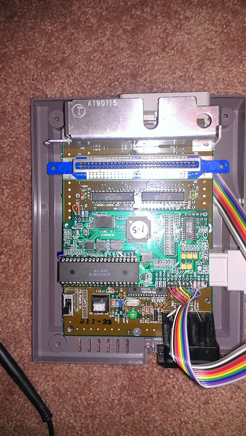
Maybe if you can post a photo of your install we might see something... I hate to make too many guesses about fairly simple mistakes that you might or might not have made... But for a real simple stab in the dark, I'd check
1: How is the NESRGB being powered? If you're not using a separate power supply for it, you need to short out J3.
2: The adaptor board is oriented the right way, right?
3: The PPU is mounted in the set of pins farther from the edge of the board, right?
Also, when you say "Same in RGB or composite" - which composite are you using? The original composite from the PPU, or the composite being generated by the NESRGB? (If you didn't cut a trace on the motherboard and route a wire from the NESRGB "V" line to the composite pin on the multi-out connector, it's PPU video)
Re: NESRGB board available now
1. I have J3 shorted.
2. I accidentally mounted the adapter board upside down, but that shouldn't matter, should it? Doesn't it just shift the pins?
3. The PPU is mounted in the correct place.
Using Composite from NESRGB

2. I accidentally mounted the adapter board upside down, but that shouldn't matter, should it? Doesn't it just shift the pins?
3. The PPU is mounted in the correct place.
Using Composite from NESRGB
ms06fz wrote:Maybe if you can post a photo of your install we might see something... I hate to make too many guesses about fairly simple mistakes that you might or might not have made... But for a real simple stab in the dark, I'd check
1: How is the NESRGB being powered? If you're not using a separate power supply for it, you need to short out J3.
2: The adaptor board is oriented the right way, right?
3: The PPU is mounted in the set of pins farther from the edge of the board, right?
Also, when you say "Same in RGB or composite" - which composite are you using? The original composite from the PPU, or the composite being generated by the NESRGB? (If you didn't cut a trace on the motherboard and route a wire from the NESRGB "V" line to the composite pin on the multi-out connector, it's PPU video)
-
eightbitminiboss
- Posts: 450
- Joined: Mon Sep 17, 2012 9:01 pm
Re: NESRGB board available now
daskrabs wrote:1. I have J3 shorted.
2. I accidentally mounted the adapter board upside down, but that shouldn't matter, should it? Doesn't it just shift the pins?
3. The PPU is mounted in the correct place.
Using Composite from NESRGB
ms06fz wrote:Maybe if you can post a photo of your install we might see something... I hate to make too many guesses about fairly simple mistakes that you might or might not have made... But for a real simple stab in the dark, I'd check
1: How is the NESRGB being powered? If you're not using a separate power supply for it, you need to short out J3.
2: The adaptor board is oriented the right way, right?
3: The PPU is mounted in the set of pins farther from the edge of the board, right?
Also, when you say "Same in RGB or composite" - which composite are you using? The original composite from the PPU, or the composite being generated by the NESRGB? (If you didn't cut a trace on the motherboard and route a wire from the NESRGB "V" line to the composite pin on the multi-out connector, it's PPU video)
Installing the adapter board upside down probably does matter...

Re: NESRGB board available now
Yeah. Looking at the traces on the adapter board, not all pins are shifted. Some are dead ends. If you flip it then you will change this.