NESRGB board available now
Re: NESRGB board available now
I just installed one of these the other day and everything went successful except I'm experiencing the same issues as tzakiel. I get this horizontal ghosting right after a pattern into a solid color. It is apparent in rgb,s video and slightly in composite. Is the only way to fix this by changing the caps before the rgb lines or changing the voltage regulator as others have suggested.
Re: NESRGB board available now
In the past week I've done 3 NESRGB installs with no issues. But in 1 I did notice that the caps in the RF enclosure were leaking. In these cases, I replace the capsand the 7805. Always test the console before starting any work.
Also. can you post pics of install?
Also. can you post pics of install?
Re: NESRGB board available now
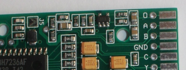
Guys, on Top Loader I can get the audio input A on R4, right? And audio input B, I grab on R5, correct?
Also, in some videos I remember Jason from gametech mentioning some issues with a video encoder amp, should I always remove it or just in cause of trouble?
Also, in some videos I remember Jason from gametech mentioning some issues with a video encoder amp, should I always remove it or just in cause of trouble?
Re: NESRGB board available now
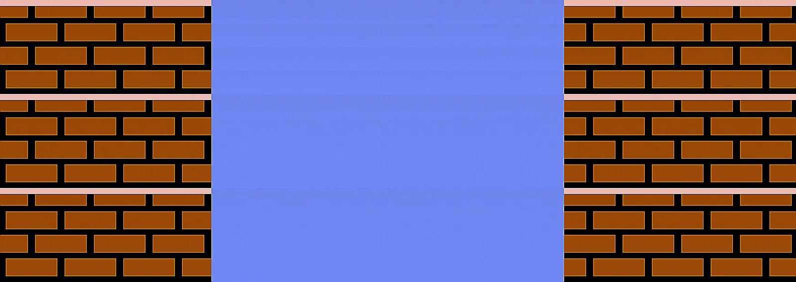
Here is a pic of the issue. It is a faint smearing of the brick pattern between the bricks.

Here is the mod I did.

I checked all the joints for continuity and made sure there was no solder connections shorted together.
The picture is gorgeous otherwise so I'm not so sure I screwed up the mod. I also changed all the electrolytic capacitors with a kit
prior to installing the nes rgb.
Here is the mod I did.
I checked all the joints for continuity and made sure there was no solder connections shorted together.
The picture is gorgeous otherwise so I'm not so sure I screwed up the mod. I also changed all the electrolytic capacitors with a kit
prior to installing the nes rgb.
Re: NESRGB board available now
It's not caps it's a bad voltage regulator. The problem is clearly widespread now with the recent boards. You can either put a filter cap on or replace the regulator or send to Tim I guess. He posted about this a while back. But it seems like a lot of people are now getting this problem.Sega90s wrote:Here is a pic of the issue. It is a faint smearing of the brick pattern between the bricks.
Here is the mod I did.
I checked all the joints for continuity and made sure there was no solder connections shorted together.
The picture is gorgeous otherwise so I'm not so sure I screwed up the mod. I also changed all the electrolytic capacitors with a kit
prior to installing the nes rgb.
Re: NESRGB board available now
Is this a plasma tv?

Re: NESRGB board available now
Don't be so quick to jump to conclusions of an entire bad batch.tzakiel wrote:It's not caps it's a bad voltage regulator. The problem is clearly widespread now with the recent boards. You can either put a filter cap on or replace the regulator or send to Tim I guess. He posted about this a while back. But it seems like a lot of people are now getting this problem.Sega90s wrote:Here is a pic of the issue. It is a faint smearing of the brick pattern between the bricks.
Here is the mod I did.
I checked all the joints for continuity and made sure there was no solder connections shorted together.
The picture is gorgeous otherwise so I'm not so sure I screwed up the mod. I also changed all the electrolytic capacitors with a kit
prior to installing the nes rgb.
I have about 20 consumer RGB sets here, some show ghosting on the logs some don't. Most can be tuned out.
Not questioning everyone's eyes, just saying make sure it's not your set before replacing the regulator.
Re: NESRGB board available now
This Tv is in fact a panasonic plasma. Its a later model that are supposed to not have the image retention issue as bad as the first ones. It is being fed the signal from a framemeister through a scart cable that is using csync. This same cable I use on my super nintendo mini and the sync line has a 330ohm resistor in it. The snes doesn't appear to have this issue, but I guess I will check the LCD I have as well as the 2 CRTs using component. The CRTs I don't currently use as they are 36" tubes that I have found no good way to child proof.
-
Einzelherz

- Posts: 1279
- Joined: Wed Apr 09, 2014 2:09 am
Re: NESRGB board available now
It's very possibly the TV. My Panasonic 42S60 does this with games and some cartoons (South Park is common). Dark lines have faint horizontal trails inside of lighter colors.
-
nmalinoski
- Posts: 1974
- Joined: Wed Jul 19, 2017 1:52 pm
Re: NESRGB board available now
I noticed this behavior with my Samsung LN32B360 for the first time the other day while watching Big Mouth. Luckily, it's not noticeable from a distance.Einzelherz wrote:It's very possibly the TV. My Panasonic 42S60 does this with games and some cartoons (South Park is common). Dark lines have faint horizontal trails inside of lighter colors.
-
bobrocks95

- Posts: 3473
- Joined: Mon Apr 30, 2012 2:27 am
- Location: Kentucky
Re: NESRGB board available now
My older ~2006 plasma does this with all sources, digital or otherwise. I assumed it was just a flaw with plasmas in general.
PS1 Disc-Based Game ID BIOS patch for MemCard Pro and SD2PSX automatic VMC switching.
Re: NESRGB board available now
Yeah... same here with my 2015 LG plasma.bobrocks95 wrote:My older ~2006 plasma does this with all sources, digital or otherwise. I assumed it was just a flaw with plasmas in general.
-
bobrocks95
- Posts: 3473
- Joined: Mon Apr 30, 2012 2:27 am
- Location: Kentucky
Re: NESRGB board available now
That's a bummer, I figured mine was old and surely they'd have fixed the problem later on. I don't recall finding much info on it either when I searched around, as if people kind of ignored the problem given plasma's other benefits.Ripthorn wrote:Yeah... same here with my 2015 LG plasma.bobrocks95 wrote:My older ~2006 plasma does this with all sources, digital or otherwise. I assumed it was just a flaw with plasmas in general.
PS1 Disc-Based Game ID BIOS patch for MemCard Pro and SD2PSX automatic VMC switching.
-
mikejmoffitt

- Posts: 629
- Joined: Fri Jan 08, 2016 7:26 am
- Location: Tokyo, Japan
Re: NESRGB board available now
I have seen this problem on the last few NESRGB boards I've installed. Plasma or not, it is something that has been cropping up recently.

Re: NESRGB board available now
I agree with Mike. I've seen it on CRT and LCD screens. Some show it more than others but the problem is there in the source video from the board.
Re: NESRGB board available now
Sega90s wrote:Here is a pic of the issue. It is a faint smearing of the brick pattern between the bricks.
Here is the mod I did.
I checked all the joints for continuity and made sure there was no solder connections shorted together.
The picture is gorgeous otherwise so I'm not so sure I screwed up the mod. I also changed all the electrolytic capacitors with a kit
prior to installing the nes rgb.
This smearing distortion looks like a voltage error/line droop to me. Or more specifically, video/field tilt.
Looking at your picture, it looks like you have the AC coupling capacitors stacked in series with what's in the cable. If you have 220uF on the NESRGB board (and are using a multi-out) you'll also have 220uF in the cable. The net result of that is 110uF of capacitance.
You want (at minimum) 200uF to minimalize field tilt distortions.

Re: NESRGB board available now
I've investigated the problem of the unstable NESRGB voltage regulator. I tested the regulators on some recent boards and compared them with the regulators on some old (faulty) boards. I came to the conclusion that the voltage regulators fitted to recent boards are fakes. When asked, the supplier admitted she was selling fake parts.
All NESRGB boards sold this year are affected.
I think most are working OK (otherwise I'd have heard about this problem much sooner), but some are oscillating or performing poorly. The most likely reason for this is the type and value of the output capacitor on the NESRGB board is suited to the genuine part, not the fake part. The addition of a capacitor on the 3.3V rail should be enough to solve stability problems.
More info here. http://etim.net.au/nesrgb/background_fault/
Re: NESRGB board available now
OMG!!!
Time to switch suppliers Tim!! Even if the price goes up, as an installer, I would pay the difference to make sure I get real components that will last for many years!
Time to switch suppliers Tim!! Even if the price goes up, as an installer, I would pay the difference to make sure I get real components that will last for many years!
Re: NESRGB board available now
Looks like I will have to remove the caps on board as voultar suggested or make a custom snes cable without the 220uf caps. Would there be a benefit of one over the other? It also looks like I'll have to change the regulator to a genuine MCP1703T-3302E/MB. Is there any good place to source these? I used to have a mouser account years ago, but found their website and shipping method to be cumbersome for small quantities.
Re: NESRGB board available now
I just purchased 10 and will only use 2 max, ended up costing around $1 each after tax.
If anyone is keen PM me.
If anyone is keen PM me.
Re: NESRGB board available now
Thanks for getting to the bottom of this, Tim. Will you be replacing this fake regulator with a genuine component on NESRGB kits from now on?viletim wrote:I've investigated the problem of the unstable NESRGB voltage regulator. I tested the regulators on some recent boards and compared them with the regulators on some old (faulty) boards. I came to the conclusion that the voltage regulators fitted to recent boards are fakes. When asked, the supplier admitted she was selling fake parts.
All NESRGB boards sold this year are affected.
I think most are working OK (otherwise I'd have heard about this problem much sooner), but some are oscillating or performing poorly. The most likely reason for this is the type and value of the output capacitor on the NESRGB board is suited to the genuine part, not the fake part. The addition of a capacitor on the 3.3V rail should be enough to solve stability problems.
More info here. http://etim.net.au/nesrgb/background_fault/

Re: NESRGB board available now
Yup, bad regulator. Got one of these as well to rework. Adding a 10uF electrolytic capacitor on the 3v3 output definitely helps, but doesn't fix the problem 100%. Definitely not a reason to go remove the onboard 220uF tantalums unless you want to go on a wild goose chase!tzakiel wrote:It's not caps it's a bad voltage regulator. The problem is clearly widespread now with the recent boards. You can either put a filter cap on or replace the regulator or send to Tim I guess. He posted about this a while back. But it seems like a lot of people are now getting this problem.Sega90s wrote:Here is a pic of the issue. It is a faint smearing of the brick pattern between the bricks.
Here is the mod I did.
I checked all the joints for continuity and made sure there was no solder connections shorted together.
The picture is gorgeous otherwise so I'm not so sure I screwed up the mod. I also changed all the electrolytic capacitors with a kit
prior to installing the nes rgb.
Re: NESRGB board available now
Tim now recommends a 22 or 47uf cap rather than a 10uF. I assume that will help more completely eliminate the noise.
Re: NESRGB board available now
Ahh... I see that in Tim's update/guide. Looks like hot air isn't required if you have the right iron tip to remove the bad/fake regulator and have just the tip for this!tzakiel wrote:Tim now recommends a 22 or 47uf cap rather than a 10uF. I assume that will help more completely eliminate the noise.
Re: NESRGB board available now
RGBSource wrote: Adding a 10uF electrolytic capacitor on the 3v3 output definitely helps, but doesn't fix the problem 100%. Definitely not a reason to go remove the onboard 220uF tantalums unless you want to go on a wild goose chase!
https://youtu.be/yS-izG2EmVg?t=22m17s
@RGBSource It's actually very basic. It's AC coupled video and the capacitance is critical. Having anything <200uF and you are violating characteristics which may yield voltage errors and excessive line-tilt distortions. The appearance of this distortion is similar as what you see in the picture,. Stacking AC coupling capacitors like that in series should be avoided, regardless.
Keith Jack's "Video Demystified" is a great book to read if you're interested in learning about analog video and how it actually works: https://books.google.com/books?id=6dgWB ... lt&f=false
Re: NESRGB board available now
There's nothing wrong with placing additional capacitors in series on the RGB lines. It reduces the total series capacitance to about 110u but there's no harm in that.Voultar wrote:@RGBSource It's actually very basic. It's AC coupled video and the capacitance is critical. Having anything <200uF and you are violating characteristics which may yield voltage errors and excessive line-tilt distortions. The appearance of this distortion is similar as what you see in the picture,. Stacking AC coupling capacitors like that in series should be avoided, regardless.
Line tilt isn't really worth worrying about. Try this experiment: Place a 22u (yes, ten times smaller than recommended) capacitor in series with each video signal. Connect your best monitor, play your most familiar game and try to spot the line tilt distortion. Can you see it?
For video signals with sync, its better to keep the coupling cap large (>200u), else the sync separator might have trouble with it.
Re: NESRGB board available now
viletim wrote:There's nothing wrong with placing additional capacitors in series on the RGB lines. It reduces the total series capacitance to about 110u but there's no harm in that.Voultar wrote:@RGBSource It's actually very basic. It's AC coupled video and the capacitance is critical. Having anything <200uF and you are violating characteristics which may yield voltage errors and excessive line-tilt distortions. The appearance of this distortion is similar as what you see in the picture,. Stacking AC coupling capacitors like that in series should be avoided, regardless.
Line tilt isn't really worth worrying about. Try this experiment: Place a 22u (yes, ten times smaller than recommended) capacitor in series with each video signal. Connect your best monitor, play your most familiar game and try to spot the line tilt distortion. Can you see it?
For video signals with sync, its better to keep the coupling cap large (>200u), else the sync separator might have trouble with it.

With respect, Tim. I have to disagree with you here. If you go down that route, you're making your equipment vulnerable to a lot of corner cases that can easily be avoided. I don't consider this to be subjective when we can reproduce objective results.
I think that there are a lot of factors that should be considered. For example: If the equipment (TV, Monitor, Scaler) you're plugging into doesn't have a comprehensive feedback network, there's not going to be that wiggle room that'll give you that DC drift allowance which will make this distortion less prominent. I agree that the observable effect isn't going to be consistently the same for everyone. And yes you're absolutely right, it isn't harmful. But the visual end-result isn't absolute.
Ste of HD Rectalvision modeled a "tilt" test in Spice.
From top to bottom, 100uF, 220uF and 470uF in order. Green is DC coupled. Red is AC coupled with those same values.


Your 22uF test will yield distortion over a variety of end-devices, including my own as halving the AC coupling capacitance to 110uF makes it visually observable for me, at least. If you watched that Youtube clip that I linked, that's exactly why I took the time to talk about it.
Several NESRGB systems have made their way to me with AC coupling capacitors stacked in series like this. Two speed-runners, most nostably who had one of those 3D printed multi-out connectors installed. Once this was corrected, those visual distortions become less apparent to negligible levels, visually.
Also, Tim. Check your E-mail.
Re: NESRGB board available now
Can anyone give me a little help?
I just received my NES Top Loader with NESRGB. The famicom audio mod is already done, but now I have to mod my adapter.


I'm not sure where is the pin 54 and 51
I just received my NES Top Loader with NESRGB. The famicom audio mod is already done, but now I have to mod my adapter.
I'm not sure where is the pin 54 and 51
-
PixelDharma
- Posts: 108
- Joined: Tue Jan 18, 2011 6:47 am
Re: NESRGB board available now
Hi everyone. I had someone install the NESRGB in my AV Famcom, but now I've got to connect the expansion audio by myself. I'm a total noob but I know how to solder.viletim wrote:Try this circuit for expansion audio.
Resistor R3 must be mounted on the NESRGB board with one leg in the mixing hole (right near the label J5).
For the NES you must put the switch in the mute position when normal (no extra audio) games are on otherwise you will get noise. For the Famicom AV you need to isolate the cartridge pins 45 and 46 before connecting wires. If you only play cartridges or Everdrive you can leave out the switch. I don't know if the audio level is correct for the RetroUSB Powerpak.
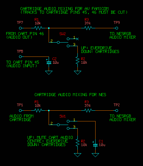
In this schematic, I believe the arrow pointing down is "ground" (specifically signal ground). Just to be sure, what is ground in this case? Literally the GND on the NESRGB? Or something else on the AV Famicom motherboard itself?
Thanks!
Re: NESRGB board available now
While the information shared is interesting and all, it's a tangent to the actual root cause - incorrect voltage regulator (plus something elseviletim wrote:There's nothing wrong with placing additional capacitors in series on the RGB lines. It reduces the total series capacitance to about 110u but there's no harm in that.Voultar wrote:@RGBSource It's actually very basic. It's AC coupled video and the capacitance is critical. Having anything <200uF and you are violating characteristics which may yield voltage errors and excessive line-tilt distortions. The appearance of this distortion is similar as what you see in the picture,. Stacking AC coupling capacitors like that in series should be avoided, regardless.
Line tilt isn't really worth worrying about. Try this experiment: Place a 22u (yes, ten times smaller than recommended) capacitor in series with each video signal. Connect your best monitor, play your most familiar game and try to spot the line tilt distortion. Can you see it?
For video signals with sync, its better to keep the coupling cap large (>200u), else the sync separator might have trouble with it.
Here's a teaser (using a direct cable/no caps in cable):