You're a saint, skips. I just responded to your email.Skips wrote: If its an AV Famicom I will do ONE more. I shot you an e-mail.
NESRGB board available now
-
The_Atomik_Punk!
- Posts: 110
- Joined: Mon Mar 10, 2014 3:47 pm
- Location: Toronto, Canada
Re: NESRGB board available now
-
Sixfortyfive
- Posts: 212
- Joined: Mon Sep 17, 2007 6:31 am
Re: NESRGB board available now
Can't remember if a resolution for this issue was discussed thoroughly or not already, but I've had success in eliminating those diagonal jailbars by using CS# for sync instead of V:
http://www.neogaf.com/forum/showpost.ph ... count=4496
http://www.neogaf.com/forum/showpost.ph ... count=4496
Re: NESRGB board available now
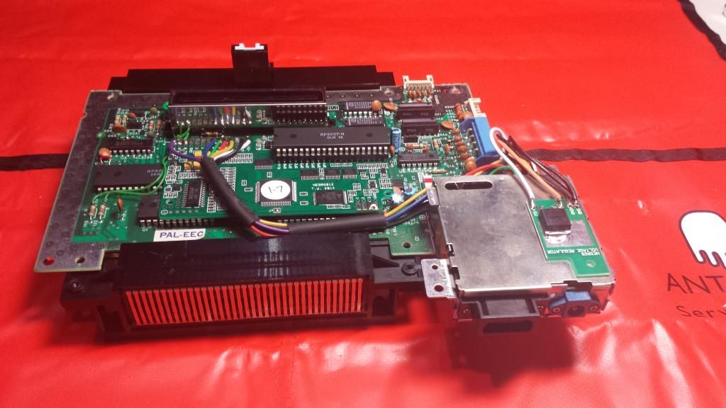
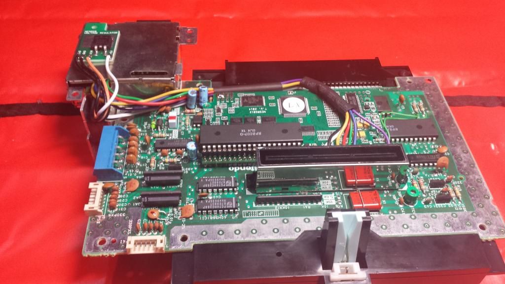
I installed a NESRGB board into my recently acquired Famicom Twin. I'll have an installation guide ready soon.
As many have mentioned, the audio mixing on this console is no good. The FDS audio is mixed in so loud that it drowns out the NES audio. As an example, here's a recording of the title screen music from Hikari Shinwa: Parutena no Kagami (Kid Icarus).
http://etim.net.au/nesrgb/installation- ... iginal.mp3
I traced out the audio circuit and compared it with the circuit diagram for the Nintendo FDS.
Here's the audio circuit from my FC Twin.
http://etim.net.au/nesrgb/installation- ... _audio.pdf
The FDS circuit diagram can be downloaded here.
http://green.ap.teacup.com/junker/119.html
The audio mixer circuit for the FC Twin is pretty much the same as the Famicom + Nintendo FDS. Except in one place... This is the audio buffer amp for the FDS section of the FC Twin. Notice the resistor values have been transposed. This makes the gain three times higher that it should be.
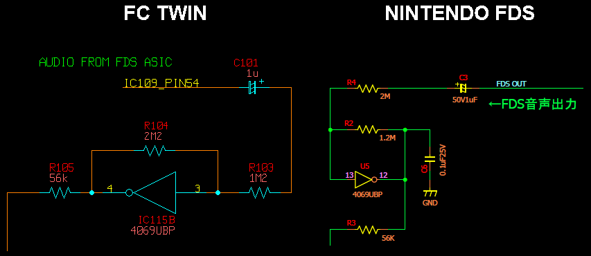
I swapped around R104 and R103. It sounds normal now.
http://etim.net.au/nesrgb/installation- ... -fixed.mp3
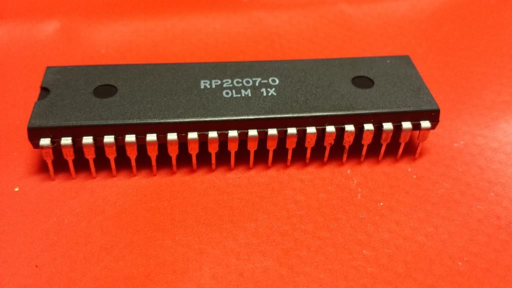
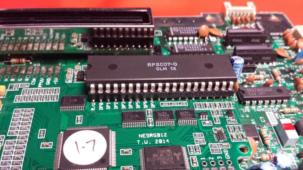
I'll include these details in my installation guide (with pictures). I don't know if all FC Twins have this problem. I suspect mine is an early unit as the PPU has a heat sink and the A/V out connector has a full set of pins. I would be surprised if this wasn't fixed at some point in the console's life, but who knows...
As many have mentioned, the audio mixing on this console is no good. The FDS audio is mixed in so loud that it drowns out the NES audio. As an example, here's a recording of the title screen music from Hikari Shinwa: Parutena no Kagami (Kid Icarus).
http://etim.net.au/nesrgb/installation- ... iginal.mp3
I traced out the audio circuit and compared it with the circuit diagram for the Nintendo FDS.
Here's the audio circuit from my FC Twin.
http://etim.net.au/nesrgb/installation- ... _audio.pdf
The FDS circuit diagram can be downloaded here.
http://green.ap.teacup.com/junker/119.html
The audio mixer circuit for the FC Twin is pretty much the same as the Famicom + Nintendo FDS. Except in one place... This is the audio buffer amp for the FDS section of the FC Twin. Notice the resistor values have been transposed. This makes the gain three times higher that it should be.
I swapped around R104 and R103. It sounds normal now.
http://etim.net.au/nesrgb/installation- ... -fixed.mp3
I'll include these details in my installation guide (with pictures). I don't know if all FC Twins have this problem. I suspect mine is an early unit as the PPU has a heat sink and the A/V out connector has a full set of pins. I would be surprised if this wasn't fixed at some point in the console's life, but who knows...
Re: NESRGB board available now
I'm looking forward to this guide. I just ordered a kit and will be putting it into my Famicom Twin. I'm a little nervous as it is a AN-505-RD and I don't want anything to go wrong. I'm curious and not sure what to do about all the audio stuff related to the Twin, so it's nice to see it under scrutiny.viletim wrote:I installed a NESRGB board into my recently acquired Famicom Twin. I'll have an installation guide ready soon.
I wonder if anyone has a better idea of the video connector type I should use? Am I correct that the Twin uses an 8 pin POL type connector for RF Video? I guess an 8 Pin Mini DIN would be good in it's place? That way I don't have to cut the case at all (I don't want any of that). What Japanese RGB cables should I use? I read in previous posts that the Neo Geo 21 Pin RGB works well and I believe uses the 8 pin Mini DIN.
For reference, my twin famicom will be played on my X68000 monitor through the XRGB-2. Eventually I will get a Framemeister and will use it on my HDTV.
Re: NESRGB board available now
Does this model suffer from the same problem? According to Wikipedia it came out a year after the AN-500. I would have thought somebody at Sharp might have picked up on it by then. Assuming it was just a clerical error to begin with...gatsu25 wrote:I'm looking forward to this guide. I just ordered a kit and will be putting it into my Famicom Twin. I'm a little nervous as it is a AN-505-RD and I don't want anything to go wrong. I'm curious and not sure what to do about all the audio stuff related to the Twin, so it's nice to see it under scrutiny.viletim wrote:I installed a NESRGB board into my recently acquired Famicom Twin. I'll have an installation guide ready soon.
The Neo Geo RGB calbes use an 8 pin DIN connector, the same type found on the back of the Famicom Twin. You can rewire this connector to suit the Neo Geo pinout. You may need to replace the connector too, as some of them are missing pins.gatsu25 wrote:I wonder if anyone has a better idea of the video connector type I should use? Am I correct that the Twin uses an 8 pin POL type connector for RF Video? I guess an 8 Pin Mini DIN would be good in it's place? That way I don't have to cut the case at all (I don't want any of that). What Japanese RGB cables should I use? I read in previous posts that the Neo Geo 21 Pin RGB works well and I believe uses the 8 pin Mini DIN.
-
eightbitminiboss
- Posts: 450
- Joined: Mon Sep 17, 2012 9:01 pm
Re: NESRGB board available now
For reference once again: http://shmups.system11.org/viewtopic.ph ... 1#p1030961viletim wrote:Does this model suffer from the same problem? According to Wikipedia it came out a year after the AN-500. I would have thought somebody at Sharp might have picked up on it by then. Assuming it was just a clerical error to begin with...gatsu25 wrote:I'm looking forward to this guide. I just ordered a kit and will be putting it into my Famicom Twin. I'm a little nervous as it is a AN-505-RD and I don't want anything to go wrong. I'm curious and not sure what to do about all the audio stuff related to the Twin, so it's nice to see it under scrutiny.viletim wrote:I installed a NESRGB board into my recently acquired Famicom Twin. I'll have an installation guide ready soon.
The Neo Geo RGB calbes use an 8 pin DIN connector, the same type found on the back of the Famicom Twin. You can rewire this connector to suit the Neo Geo pinout. You may need to replace the connector too, as some of them are missing pins.gatsu25 wrote:I wonder if anyone has a better idea of the video connector type I should use? Am I correct that the Twin uses an 8 pin POL type connector for RF Video? I guess an 8 Pin Mini DIN would be good in it's place? That way I don't have to cut the case at all (I don't want any of that). What Japanese RGB cables should I use? I read in previous posts that the Neo Geo 21 Pin RGB works well and I believe uses the 8 pin Mini DIN.
I am intrigued that your RF connector was fully pinned Tim. The two Twins I have are not, but they are the same model so I follow the same credence you have that it's a revision thing.
Re: NESRGB board available now
It might very well not, I haven't actually noticed any obvious problems with the sound, but I will give it a closer inspection later. I also was taking about the extra channels on the Disk and how to output the audio once I get the NESRGB in there. It seems like the best course of action would be to just continue going through the original audio jacks and not bother wiring any audio. That is possible correct?viletim wrote:Does this model suffer from the same problem? According to Wikipedia it came out a year after the AN-500. I would have thought somebody at Sharp might have picked up on it by then. Assuming it was just a clerical error to begin with...
I haven't looked to see if mine has missing pins yet. I will check it though. I am curious about your reference picture. Is that board that is wired to the NESRGB the original board from the twin that connects the power and audio/video outputs? Mine was a tan color, but I didn't see the underneath side of it.eightbitminiboss wrote:For reference once again: http://shmups.system11.org/viewtopic.ph ... 1#p1030961
I am intrigued that your RF connector was fully pinned Tim. The two Twins I have are not, but they are the same model so I follow the same credence you have that it's a revision thing.
-
eightbitminiboss
- Posts: 450
- Joined: Mon Sep 17, 2012 9:01 pm
Re: NESRGB board available now
Yes, the topside is tan, the underside will be green.gatsu25 wrote:It might very well not, I haven't actually noticed any obvious problems with the sound, but I will give it a closer inspection later. I also was taking about the extra channels on the Disk and how to output the audio once I get the NESRGB in there. It seems like the best course of action would be to just continue going through the original audio jacks and not bother wiring any audio. That is possible correct?viletim wrote:Does this model suffer from the same problem? According to Wikipedia it came out a year after the AN-500. I would have thought somebody at Sharp might have picked up on it by then. Assuming it was just a clerical error to begin with...
I haven't looked to see if mine has missing pins yet. I will check it though. I am curious about your reference picture. Is that board that is wired to the NESRGB the original board from the twin that connects the power and audio/video outputs? Mine was a tan color, but I didn't see the underneath side of it.eightbitminiboss wrote:For reference once again: http://shmups.system11.org/viewtopic.ph ... 1#p1030961
I am intrigued that your RF connector was fully pinned Tim. The two Twins I have are not, but they are the same model so I follow the same credence you have that it's a revision thing.
Re: NESRGB board available now
eightbitminiboss wrote: For reference once again: http://shmups.system11.org/viewtopic.ph ... 1#p1030961
I am intrigued that your RF connector was fully pinned Tim. The two Twins I have are not, but they are the same model so I follow the same credence you have that it's a revision thing.
Also, I don't see any ground connection in your picture. Is there a reason for that or did you just not have it connected at that point?
-
eightbitminiboss
- Posts: 450
- Joined: Mon Sep 17, 2012 9:01 pm
Re: NESRGB board available now
On which end? If you're talking about the DIN connector side, I believe I jumped it to the ground plane on the board. I forgot what I did...gatsu25 wrote:eightbitminiboss wrote: For reference once again: http://shmups.system11.org/viewtopic.ph ... 1#p1030961
I am intrigued that your RF connector was fully pinned Tim. The two Twins I have are not, but they are the same model so I follow the same credence you have that it's a revision thing.
Also, I don't see any ground connection in your picture. Is there a reason for that or did you just not have it connected at that point?
Re: NESRGB board available now
I mean there is no ground connection from the NESRGB Board to pin 2 on the DIN connection to the power board. I assume that needs to be done, you just didn't yet in your picture?eightbitminiboss wrote:On which end? If you're talking about the DIN connector side, I believe I jumped it to the ground plane on the board. I forgot what I did...gatsu25 wrote:eightbitminiboss wrote: For reference once again: http://shmups.system11.org/viewtopic.ph ... 1#p1030961
I am intrigued that your RF connector was fully pinned Tim. The two Twins I have are not, but they are the same model so I follow the same credence you have that it's a revision thing.
Also, I don't see any ground connection in your picture. Is there a reason for that or did you just not have it connected at that point?
Thanks for the guide! For clarification, when you are soldering the Jumpers, what exactly do you mean? They just need to have solder on them, or do you actually need to connect them somewhere?viletim wrote:Guide for installing a NESRGB into a Famicom Twin
Re: NESRGB board available now
Just put a dab of solder on there to join the two pads.gatsu25 wrote:Thanks for the guide! For clarification, when you are soldering the Jumpers, what exactly do you mean? They just need to have solder on them, or do you actually need to connect them somewhere?
-
eightbitminiboss
- Posts: 450
- Joined: Mon Sep 17, 2012 9:01 pm
Re: NESRGB board available now
Oh, yeah that's connected. It was done after taking the picture while doing some initial troubleshooting with sync signals on my setup.gatsu25 wrote: I mean there is no ground connection from the NESRGB Board to pin 2 on the DIN connection to the power board. I assume that needs to be done, you just didn't yet in your picture?
Re: NESRGB board available now
Tim (hope you read this) what are the chances of a famicom solution in the next 12 months? I think there's a lot of people waiting to see what would happen with this last system.
-
bobrocks95

- Posts: 3472
- Joined: Mon Apr 30, 2012 2:27 am
- Location: Kentucky
Re: NESRGB board available now
Well, I do remember Tim saying that he wanted to finish the Famicom quickly so he could finally move on to other projects, since I'm sure processing orders and revising code and hardware has been really time consuming. An update on progress would be nice.
PS1 Disc-Based Game ID BIOS patch for MemCard Pro and SD2PSX automatic VMC switching.
Re: NESRGB board available now
I got my RGB Modded PAL Frontloader today and realized besides the diagonal lines also that vertical lines have diagonal steps like here the flagpole:

Does anyone know what's wrong in this case? I use the RGB connection.
Does anyone know what's wrong in this case? I use the RGB connection.
Re: NESRGB board available now
I could solve the problem. Tim answered us the solution:
"Have you set your jumpers correctly? PAL consoles need J7 and J4 closed."
After closing J7 and J4 the picture is great now!
"Have you set your jumpers correctly? PAL consoles need J7 and J4 closed."
After closing J7 and J4 the picture is great now!
Re: NESRGB board available now
I am planning on installing the NESRGB board over the weekend but I don't have all the parts needed for my cable and I don't have my 8 pin DIN PCB type in the mail yet either. I want to make sure the PPU and everything is working properly still before I work on wiring the cable up. Will I still be able to use the composite cable with the board installed? Do I need to wire anything else from the NESRGB if I just want to use that for now or just leave it like it is? I'm using a famicom twin if that makes any difference.
Re: NESRGB board available now
Depends on how you wire it. If you just install a NESRGB and don't wire up any connectors to the NESRGB's video outputs, you'll just get the PPU's composite signal. You can still use this by turning the NESRGB off using the palette switch, but it's not a very useful test of the NESRGB itself. (The NESRGB uses the PPU's composite signal in order to obtain some information about the palette index of the current pixel - so when NESRGB is active the PPU outputs a two-color grayscale image.)gatsu25 wrote:I am planning on installing the NESRGB board over the weekend but I don't have all the parts needed for my cable and I don't have my 8 pin DIN PCB type in the mail yet either. I want to make sure the PPU and everything is working properly still before I work on wiring the cable up. Will I still be able to use the composite cable with the board installed? Do I need to wire anything else from the NESRGB if I just want to use that for now or just leave it like it is? I'm using a famicom twin if that makes any difference.
The NESRGB does provide a composite video signal of its own, but it's not connected to anything by default. It's also actually inferior in some ways to the composite signal: it's just kind of hazy-looking. So you could use it to test that the NESRGB is working, but it's not a very good demonstration of its capabilities. You would have to connect a line to the "V" terminal on the NESRGB to use its composite output.
S-video may also be an option (if your TV or converter accepts it) while you wait for your RGB connector. It's not as good as RGB of course but it's a huge step up from composite. (I don't have RGB or component set up yet, so right now I use S-Video exclusively for my NESRGB systems.)
hitparade: I'm glad you found the solution to your problem. I was very curious to know what was going wrong there. (I didn't even know the NESRGB worked with PAL consoles...)
Re: NESRGB board available now
Yeah, the guy who sold it to me didn't realize that the picture is wrong. The guy who installed it from him forgot to do the jumpers. Good that it was enough easy that I could solder it by myself.ms06fz wrote:hitparade: I'm glad you found the solution to your problem. I was very curious to know what was going wrong there. (I didn't even know the NESRGB worked with PAL consoles...)
Of course the NESRGB should work with PAL consoles, since the boards are from Australia where PAL is also the standard.
Now I am happy with both, Top Loader NTSC RGB and Front Loader PAL RGB
Re: NESRGB board available now
Alright, I got the NESRGB in my famicom. I wired it to S-Video since I'm waiting on some parts for my RGB Cable. All I'm getting is a terrible grey screen. Does anyone have any idea of what could possibly be wrong? I hope it's something simple (not that I broke something).
Here is a picture of the grey image on my TV.
https://dl.dropboxusercontent.com/u/175 ... AG0443.jpg
Here is a picture of the grey image on my TV.
https://dl.dropboxusercontent.com/u/175 ... AG0443.jpg
-
Einzelherz

- Posts: 1279
- Joined: Wed Apr 09, 2014 2:09 am
Re: NESRGB board available now
Grey screen means the nesrgb isn't running. You'll need to recheck your connections.
Re: NESRGB board available now
Is there a good and easy way of doing that? If I use my multimeter and check for continuity, should all the pins from the PPU correspond to the solder points on the Famicom PCB? I checked them earlier, but some of them were only showing connections to the NESRGB board itself, for example, the EXT pins.Einzelherz wrote:Grey screen means the nesrgb isn't running. You'll need to recheck your connections.
-
Monstermug

- Posts: 401
- Joined: Thu Mar 31, 2011 7:58 pm
- Location: London, UK
Re: NESRGB board available now
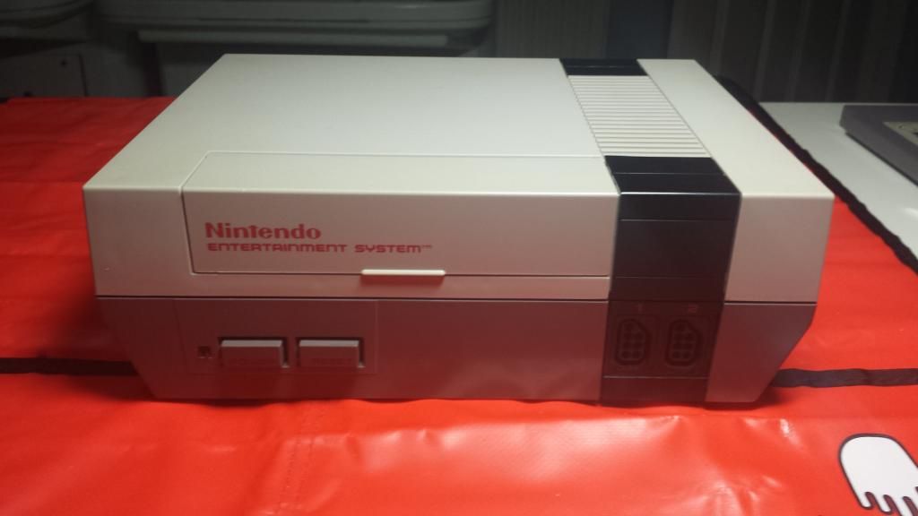
Had a few hours spare time today so I thought I work on a friend's nes. Thought I share the results.
1. I removed PPU Chip. Nice and clean =)
2. Installed a socket and mounted the NESRGB board.
3. Soldered it into place
4. Next job to wire it all up according to Tim's wiring diagram.
5. Put it all back together. Look no wires
6. Complete with multi out. Looks factory??
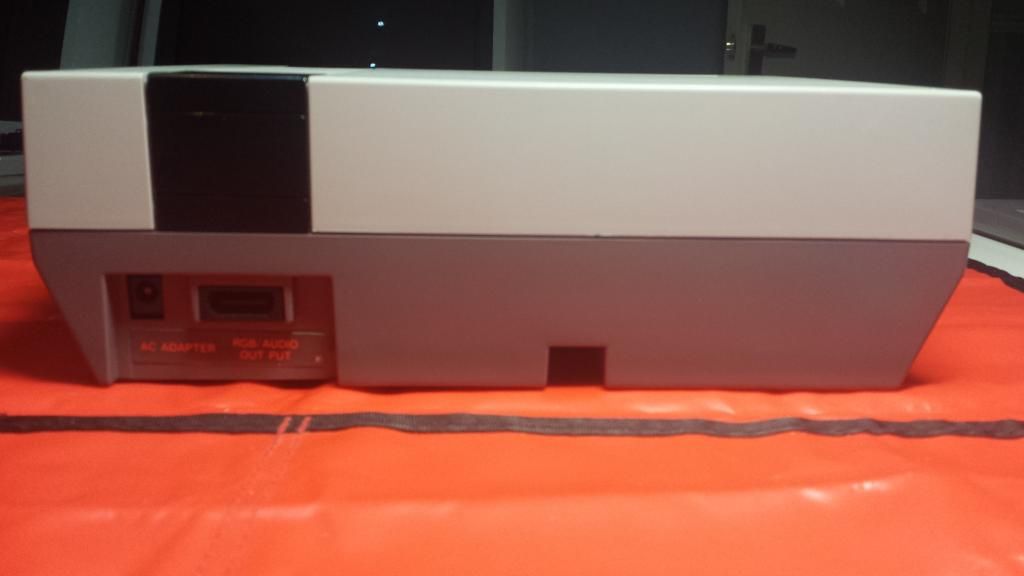
That's because it is
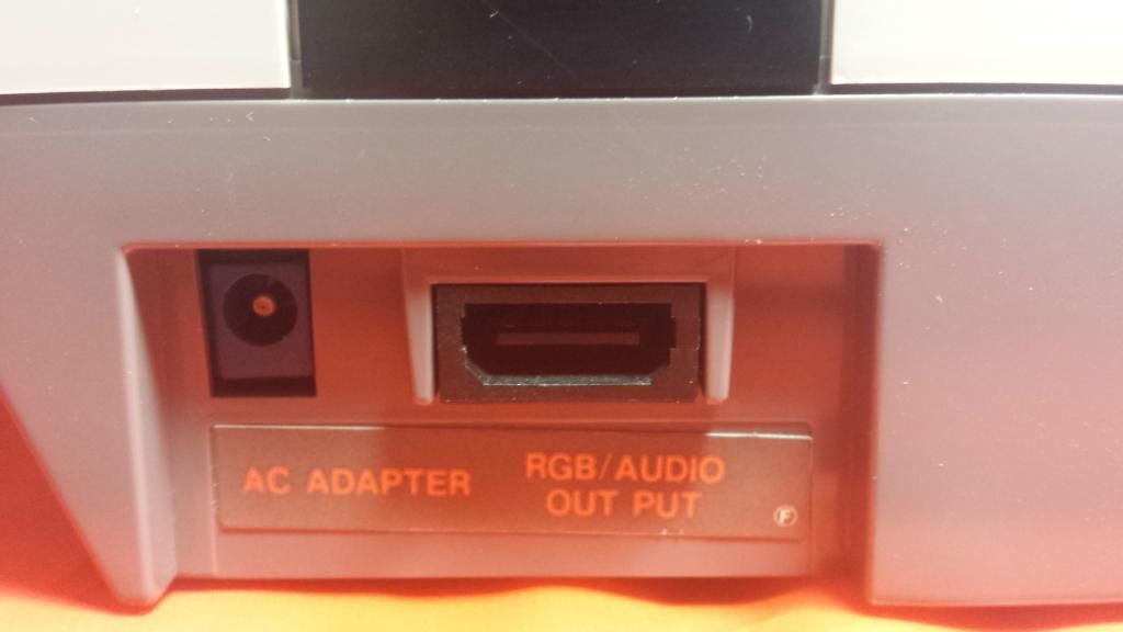
Finished Product. No damaged to the NES in anyway. Can be put back to factory at any time.
1. I removed PPU Chip. Nice and clean =)
2. Installed a socket and mounted the NESRGB board.
3. Soldered it into place
4. Next job to wire it all up according to Tim's wiring diagram.
5. Put it all back together. Look no wires
6. Complete with multi out. Looks factory??
That's because it is
Finished Product. No damaged to the NES in anyway. Can be put back to factory at any time.
-
bobrocks95
- Posts: 3472
- Joined: Mon Apr 30, 2012 2:27 am
- Location: Kentucky
Re: NESRGB board available now
So does that mean it's a French NES???
PS1 Disc-Based Game ID BIOS patch for MemCard Pro and SD2PSX automatic VMC switching.

Re: NESRGB board available now
Well seeing that the French NES is the only one with that connector, yes it is.bobrocks95 wrote:So does that mean it's a French NES???
-
Monstermug
- Posts: 401
- Joined: Thu Mar 31, 2011 7:58 pm
- Location: London, UK
Re: NESRGB board available now
Yep. NESE-01 (FRA). No need to drill any glory holes. They are fantastic to work with.
Re: NESRGB board available now
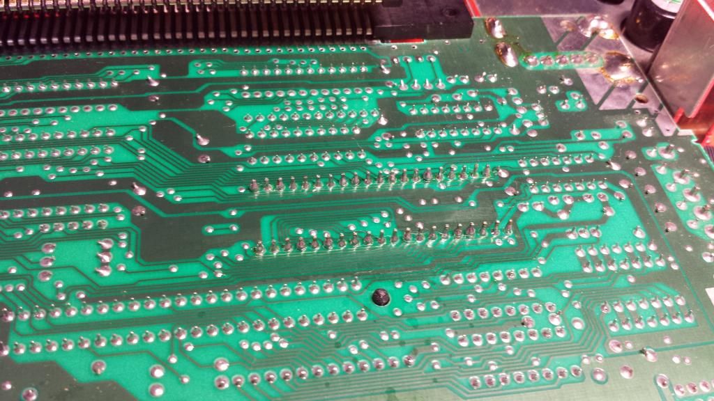
I went through every single pin on the famicom board to the PPU connected to the NESRGB. From the famicom motherboard to the PPU, every connection from A to B was straight connected except for 12 points on one side. of those points, they are DP0 through DP7, and I the EXT 0 through 3. Of all of the DP pins and Ext pins, I found connection from points from both the PPU side, and the Famicom motherboard side to individual points on the NESRGB.Einzelherz wrote:Grey screen means the nesrgb isn't running. You'll need to recheck your connections.
I really have no idea what the problem could be at this point. One thing I did not do, is use the 40 pin DIP round pin IC socket on the famicom motherboard. Instead I just used the two 20 pin round pin strips and soldered them directly from the Famicom twin adapter to the famicom motherboard. I insulated with electricians tape. I don't see how that would make any difference though.
Does anyone else have any idea why I would only be getting a grey screen on my tv? I have connected only S-video at this point using the Y, C, and ground pins, as well as closing the pallet switch with a jumper from pin 3 to ground. I have also closed J3 and J5 on the NESRGB board.
Please let me know if my explanation isn't clear.
Edit: So I made sure of all of the connections, the wire I had used for the S-Video was not copper, so I changed it to a more bendable copper type insulated wire. I got everything back together and all I get now is a totally black screen. When I changed it to disk mode, right when it turned on, it gave me a slight fuzz of color then went to black. I have no idea what to do next.
Re: NESRGB board available now
Got some photos of your install we could look at? Might be able to spot something there...gatsu25 wrote: Does anyone else have any idea why I would only be getting a grey screen on my tv? I have connected only S-video at this point using the Y, C, and ground pins, as well as closing the pallet switch with a jumper from pin 3 to ground. I have also closed J3 and J5 on the NESRGB board.