SNES/Famicon PCB Revisions and RGB Video
-
Shoryukev

- Posts: 651
- Joined: Thu Dec 10, 2015 7:18 pm
- Location: Cleveland, OH
Re: SNES/Famicon PCB Revisions and RGB Video
Both of my SNES consoles have the vertical bar, my 1-chip system is less noticeable but it's still there. It really stands out on the title screen for Final Fantasy 3...but otherwise isn't really an issue.
-
noonan2678

- Posts: 137
- Joined: Sat Feb 23, 2013 7:15 pm
- Location: Boston, MA, USA
Re: SNES/Famicon PCB Revisions and RGB Video
Same for me as above... more jailbars rather than the centered vertical bars though. It literally only shows up, faintly, in a few games I've noticed, along with the FFIII intro as many have stated. It's interesting though that many other completely black screen have no signs of it whatsoever. I'm going to add the amp anyway and I'll post the results after.
-
mvsfan
- Posts: 1209
- Joined: Sat Oct 06, 2012 12:24 am
Re: SNES/Famicon PCB Revisions and RGB Video
I cant see the stripe on my 1-chip-03.
the only console i have that i can see it on is an APU.
and i only really notice it on final fantasy 3.
the only console i have that i can see it on is an APU.
and i only really notice it on final fantasy 3.
-
AndehX

- Posts: 790
- Joined: Sun Oct 18, 2015 11:37 pm
Re: SNES/Famicon PCB Revisions and RGB Video
my PAL 1-CHIP-01 shows the vertical bar quite noticably in the background of Crateria on Super Metroid
-
RGB0b
- Posts: 543
- Joined: Wed Dec 05, 2012 1:52 pm
Re: SNES/Famicon PCB Revisions and RGB Video
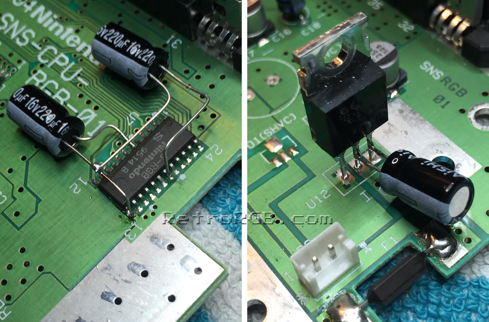
I've now had a few people tell me the 3-capacitor trick worked for them: http://www.retrorgb.com/images/SNESVert ... lVtFix.jpg
It's a totally reversible mod, so I suggest giving it a try. Also, replaceing the DC-DC converter might help as well (scroll down): http://www.retrorgb.com/snestips.html
Let me know if it works for you guys. I haven't run across a white-line console in awhile, so I haven't had the chance to test these fixes.
-
Blair

- Posts: 681
- Joined: Mon May 11, 2015 5:59 am
- Location: America
Re: SNES/Famicon PCB Revisions and RGB Video
oh that's okay, I'm just using my cheesy little android phone for taking pictures as well.FinalBaton wrote:@Blair Yes it came with an original power supply.
I'll try to take some pics. I only have my phone as a camera though, so it's not gonna do it justice
the thing that gives you the best quality for taking CRT photos is manual focus adjustment, (that's how I get such nice scanline pictures, at least I think they look nice).
and lowering the ISO, you want to get the room dark as possible and then turn your ISO down to 200 to 400 depending on how bright your screen is ( that eliminates excess grain).
if you want your colors to look right you probably have to adjust the white balance (for most PVM's I've found that setting it to sunny or florescent helps, but the auto white balance feature might work just as well).
-
Pasky

- Posts: 699
- Joined: Mon Oct 21, 2013 3:58 am
Re: SNES/Famicon PCB Revisions and RGB Video
I wouldn't recommend that DC-DC converter, you're just going to introduce switching noise into the 5V rail because it's a SMPS.retrorgb wrote:I've now had a few people tell me the 3-capacitor trick worked for them: http://www.retrorgb.com/images/SNESVert ... lVtFix.jpg
It's a totally reversible mod, so I suggest giving it a try. Also, replaceing the DC-DC converter might help as well (scroll down): http://www.retrorgb.com/snestips.html
Let me know if it works for you guys. I haven't run across a white-line console in awhile, so I haven't had the chance to test these fixes.
The capacitor trick has been known to work because it's been believed the vertical bar is caused by the power drop during the DRAM refresh. Having that capacitor on the 5V rail and regulator gives it a nice reserve so it never droops. Putting two on the video encoder is completely unnecessary. a 470uF or 1000uF (some systems have 2 vertical bars) on the 5V regulator is sufficient
-
FinalBaton

- Posts: 4475
- Joined: Sun Mar 08, 2015 10:38 pm
- Location: Québec City
Re: SNES/Famicon PCB Revisions and RGB Video
Yeah, I take my CRT pics with the lights off as well. And with low iso too (200 iso is what I rock with)Blair wrote: oh that's okay, I'm just using my cheesy little android phone for taking pictures as well.
the thing that gives you the best quality for taking CRT photos is manual focus adjustment, (that's how I get such nice scanline pictures, at least I think they look nice).
and lowering the ISO, you want to get the room dark as possible and then turn your ISO down to 200 to 400 depending on how bright your screen is ( that eliminates excess grain).
if you want your colors to look right you probably have to adjust the white balance (for most PVM's I've found that setting it to sunny or florescent helps, but the auto white balance feature might work just as well).
I don't have a manual focus on my phone though. Only 2 options : macro or normal.
-FM Synth & Black Metal-
-
RGB0b
- Posts: 543
- Joined: Wed Dec 05, 2012 1:52 pm
Re: SNES/Famicon PCB Revisions and RGB Video
Have you seen this happen with that style DC-DC converter? I've been using one for awhile and have not noticed any issues. I usually have a good eye for noise...but I realize that's a subjective statement; I never verified with a scope or anything. Was just curious if anyone else had issues.Pasky wrote:I wouldn't recommend that DC-DC converter, you're just going to introduce switching noise into the 5V rail because it's a SMPS.
I have not been able to test this myself, as the last handful of Mini's / 1CHIP's I've seen don't have any hint of a white line at all. That being said, I've had people email to tell me they needed all three caps for the line to completely disappear. I have no way to verify this at all though, I'm only relaying the information. It would be awesome if anyone here can test the issue on their SNES and see what kind of results they get.Pasky wrote:The capacitor trick has been known to work because it's been believed the vertical bar is caused by the power drop during the DRAM refresh. Having that capacitor on the 5V rail and regulator gives it a nice reserve so it never droops. Putting two on the video encoder is completely unnecessary. a 470uF or 1000uF (some systems have 2 vertical bars) on the 5V regulator is sufficient
I'm also curious if there's any possibility that adding the caps can cause adverse effects. Doubt it, but I'm not an EE.
-
Pasky
- Posts: 699
- Joined: Mon Oct 21, 2013 3:58 am
Re: SNES/Famicon PCB Revisions and RGB Video
A CRT won't show the noise as obvious as a LCD. I haven't used one in a SNES but I have in a NES and the switching noise was pretty apparent.retrorgb wrote:Have you seen this happen with that style DC-DC converter? I've been using one for awhile and have not noticed any issues. I usually have a good eye for noise...but I realize that's a subjective statement; I never verified with a scope or anything. Was just curious if anyone else had issues.Pasky wrote:I wouldn't recommend that DC-DC converter, you're just going to introduce switching noise into the 5V rail because it's a SMPS.
I have not been able to test this myself, as the last handful of Mini's / 1CHIP's I've seen don't have any hint of a white line at all. That being said, I've had people email to tell me they needed all three caps for the line to completely disappear. I have no way to verify this at all though, I'm only relaying the information. It would be awesome if anyone here can test the issue on their SNES and see what kind of results they get.Pasky wrote:The capacitor trick has been known to work because it's been believed the vertical bar is caused by the power drop during the DRAM refresh. Having that capacitor on the 5V rail and regulator gives it a nice reserve so it never droops. Putting two on the video encoder is completely unnecessary. a 470uF or 1000uF (some systems have 2 vertical bars) on the 5V regulator is sufficient
I'm also curious if there's any possibility that adding the caps can cause adverse effects. Doubt it, but I'm not an EE.
If they're saying they need the additional capacitors to make it go away then it's obviously they needed a higher capacitance capacitor not more of them, they're just putting them in parallel. Putting more bypass caps on the encoder itself does nothing, it's the 5V rail that's important as the line doesn't come from the encoder, it comes from the DRAM refresh...
-
AndehX
- Posts: 790
- Joined: Sun Oct 18, 2015 11:37 pm
Re: SNES/Famicon PCB Revisions and RGB Video
My 1-CHIP-01 has pretty noticable vertical bars. I see them on Super Metroid. So I'll put capacitor on the voltage regulator sometime over the weekend and report back how it turns out.retrorgb wrote:It would be awesome if anyone here can test the issue on their SNES and see what kind of results they get.
I'm also curious if there's any possibility that adding the caps can cause adverse effects. Doubt it, but I'm not an EE.
-
Blair
- Posts: 681
- Joined: Mon May 11, 2015 5:59 am
- Location: America
Re: SNES/Famicon PCB Revisions and RGB Video
vertical bars?
you mean you have more than one?
you mean you have more than one?
-
AndehX
- Posts: 790
- Joined: Sun Oct 18, 2015 11:37 pm
Re: SNES/Famicon PCB Revisions and RGB Video
yeah, there's like a light bar and a darker bar right next to each other in the middle of the screenBlair wrote:vertical bars?
you mean you have more than one?
you can clearly see it here:

-
tjstogy

- Posts: 341
- Joined: Tue Sep 01, 2015 1:27 am
- Location: New York
Re: SNES/Famicon PCB Revisions and RGB Video
Doing retrorgb's/bortis amp mod got rid of mine on my 1-chip-03AndehX wrote:yeah, there's like a light bar and a darker bar right next to each other in the middle of the screenBlair wrote:vertical bars?
you mean you have more than one?
you can clearly see it here:
http://retrorgb.com/1chiprgb.html
I'm still trying to figure out the weird horizontal lines I'm getting on a white text/black background (and other weird lines) on my Genesis but that's another thread...
-
AndehX
- Posts: 790
- Joined: Sun Oct 18, 2015 11:37 pm
Re: SNES/Famicon PCB Revisions and RGB Video
Yeah, im gonna try adding a 470uf capacitor to the voltage regulator first, and if that doesn't work, then i'll do the RGB amp mod.tjstogy wrote:
Doing retrorgb's/bortis amp mod got rid of mine on my 1-chip-03
http://retrorgb.com/1chiprgb.html
Oh and a bit off-topic, but I just finished painting my SNES yesterday (it was ugly and yellow)

-
RGB0b
- Posts: 543
- Joined: Wed Dec 05, 2012 1:52 pm
Re: SNES/Famicon PCB Revisions and RGB Video
I checked with a capture card directly, upscaler through a capture card, CRT and LCD. Maybe I just don't know what to look for? Is this something we can get a picture of?Pasky wrote:A CRT won't show the noise as obvious as a LCD. I haven't used one in a SNES but I have in a NES and the switching noise was pretty apparent.
Good info, thank you.Pasky wrote:If they're saying they need the additional capacitors to make it go away then it's obviously they needed a higher capacitance capacitor not more of them, they're just putting them in parallel. Putting more bypass caps on the encoder itself does nothing, it's the 5V rail that's important as the line doesn't come from the encoder, it comes from the DRAM refresh...
Thank you!AndehX wrote:My 1-CHIP-01 has pretty noticable vertical bars. I see them on Super Metroid. So I'll put capacitor on the voltage regulator sometime over the weekend and report back how it turns out.
I've personally witnessed this myself a bunch of times. That, combined with the fact that it's an easier mod (then the 3-wire), is why I recommended people use the THS7314 solution on the SNES Mini. After seeing the difference in chip sharpness (with the filter off) I'll now recommend the THS7374 solution, as soon as one is available (I believe one's about a month away). That being said, finding a "proper" solution for the vertical line, such as the cap trick would be awesome.tjstogy wrote:Doing retrorgb's/bortis amp mod got rid of mine on my 1-chip-03
-
AndehX
- Posts: 790
- Joined: Sun Oct 18, 2015 11:37 pm
Re: SNES/Famicon PCB Revisions and RGB Video
Ok, just added a 470uf capacitor to the 7805 and I can confirm it has completely fixed the vertical bar. Excuse my reflection

-
Shoryukev
- Posts: 651
- Joined: Thu Dec 10, 2015 7:18 pm
- Location: Cleveland, OH
Re: SNES/Famicon PCB Revisions and RGB Video
Excellent!!! I'm going to give it a shot with mine as well, as it looks pretty much exactly like your "before" pictureAndehX wrote:Ok, just added a 470uf capacitor to the 7805 and I can confirm it has completely fixed the vertical bar. Excuse my reflection
-
AndehX
- Posts: 790
- Joined: Sun Oct 18, 2015 11:37 pm
Re: SNES/Famicon PCB Revisions and RGB Video
I have to thank Pasky though, as he suggested that only the 1 capacitor was needed on the 7805, which he was right about.
-
Pasky
- Posts: 699
- Joined: Mon Oct 21, 2013 3:58 am
Re: SNES/Famicon PCB Revisions and RGB Video
Switching noise will usually look like a diagonal wave going in one direction over the video signal, and then going back to the other direction and repeating. If it's not visible it may be fine, but I wouldn't expect that on every SNES revision. I certainly noticed it on my NES top loader when I tried a switching 7805 replacement.retrorgb wrote:I checked with a capture card directly, upscaler through a capture card, CRT and LCD. Maybe I just don't know what to look for? Is this something we can get a picture of?
-
RGB0b
- Posts: 543
- Joined: Wed Dec 05, 2012 1:52 pm
Re: SNES/Famicon PCB Revisions and RGB Video
I'll definitely look for that. I've actually seen what you describe (through a capture card) on non-modded SNES', but didn't have the opportunity to work on them.Pasky wrote:Switching noise will usually look like a diagonal wave going in one direction over the video signal, and then going back to the other direction and repeating. If it's not visible it may be fine, but I wouldn't expect that on every SNES revision. I certainly noticed it on my NES top loader when I tried a switching 7805 replacement.
Awesome, I'll try that the next time I find a vertical line SNES.AndehX wrote:Ok, just added a 470uf capacitor to the 7805 and I can confirm it has completely fixed the vertical bar.
-
Seraphic
- Posts: 492
- Joined: Fri Mar 19, 2010 1:46 pm
Re: SNES/Famicon PCB Revisions and RGB Video
Is there another device similar to the XSYNC-1 that will take JP-21 and convert to HD-15 but not apply a LPF?RGB32E wrote:Very cool! I recall seeing the LPF pin when I installed a THS7374 in a mini 3+ years ago, but never tried bypassing the LPF!retrorgb wrote:Okay, I turned the filter off by connecting pin 9 to 5v rather then ground (page 7, thanks to db Elec for the tip): http://www.ti.com/lit/ds/symlink/ths7374.pdf
Looks like Micomsoft left provisions for bypassing the LPF in their application of the THS7374 in the XSYNC-1, but decided to enable it. I had wondered if the switch on the underside of the XSYNC-1 was a toggle for this, but have confirmed it isn't wired for that function.

R40 connects THS7374 pin 9 to ground via a 4.7k ohm resistor. R42 is left unpopulated - LHS is 5VDC, RHS is pin 9. Remove R40 and jumper (or use a resistor) R42 to bypass the LPF!
This brings up an interesting point though - The THS7314 used in many projects has an undefeatable LPF. Perhaps people can get a slight improvement in sharpness from your THS7314 circuits if you updated them for use with the THS7374!

-
RGB32E

- Posts: 1400
- Joined: Thu Nov 05, 2009 12:50 am
Re: SNES/Famicon PCB Revisions and RGB Video
It's an easy mod to disable the LPF on the XSYNC-1 - remove R40, jumper or add a resistor to R42. One could even add a switch to enable/disable the LPF!Seraphic wrote:Is there another device similar to the XSYNC-1 that will take JP-21 and convert to HD-15 but not apply a LPF?
-
Seraphic
- Posts: 492
- Joined: Fri Mar 19, 2010 1:46 pm
Re: SNES/Famicon PCB Revisions and RGB Video
That is good to know. But sounds like it requires a solder kit and some experience.RGB32E wrote:It's an easy mod to disable the LPF on the XSYNC-1 - remove R40, jumper or add a resistor to R42. One could even add a switch to enable/disable the LPF!Seraphic wrote:Is there another device similar to the XSYNC-1 that will take JP-21 and convert to HD-15 but not apply a LPF?
-
mvsfan
- Posts: 1209
- Joined: Sat Oct 06, 2012 12:24 am
Re: SNES/Famicon PCB Revisions and RGB Video
http://www.ebay.com/itm/Super-Nintendo- ... true&rt=nc
What a deal this guy got. i dont see this often anymore.
What a deal this guy got. i dont see this often anymore.
-
Guspaz

- Posts: 3242
- Joined: Tue Oct 06, 2015 7:37 pm
- Location: Montréal, Canada
Re: SNES/Famicon PCB Revisions and RGB Video
Assuming that it can be cleaned, and that whatever problem with it can be easily fixed, sure...
-
Voultar

- Posts: 550
- Joined: Fri Jan 10, 2014 8:29 pm
- Location: USA
Re: SNES/Famicon PCB Revisions and RGB Video
If you're going to use a switching regulator, put an adequate inductor on there to take the edge off.
-
tjsynkral
- Posts: 73
- Joined: Wed Jan 20, 2016 7:41 am
Re: SNES/Famicon PCB Revisions and RGB Video
Google just brings me back to your post, can you tell me more about this?CkRtech wrote:Well, you could try Tavatri's SNES Sharp Pixel mod. I think Borti was working on a PCB for it last year. Not sure what came of it. The prototyping nature of the circuit has a ton of stacked components if you try to "float it" without a PCB. Results for those that tried it have been mixed.
I may be making a few comparison photos for you guys since I have my RGB-modded Trinitron CRT and retro_console_accessories cables. My old SNES is an SHVC, and I've modded it for Component and it's giving me very sharp pixels on Component thus dodging the blurry RGB issue. I have a Snes Jr that gives me great RGB with the RetroRGB board, though I still need to add s-video to it (for convenience and luma sync). And my SFC is one of the S-RGB's, either 01 or 02, I will check later (that system is currently getting a retro bright).
-
CkRtech

- Posts: 668
- Joined: Mon Aug 27, 2012 9:30 pm
- Location: Seattle, WA
Re: SNES/Famicon PCB Revisions and RGB Video
It is a little insane as there is no PCB - so beware of stacked components. Run this through your translation of choice - http://vaot.mydns.jp/fc/sfc_sharp2.htm
-
Sid
- Posts: 78
- Joined: Mon Sep 01, 2014 3:42 am
Re: SNES/Famicon PCB Revisions and RGB Video
Managed to buy a Super Famicom with serial S2502XXXX for a measly US$19 on ebay. It would most likely be a 1CHIP-02?
Really looking forward to checking it out once it arrives.
Really looking forward to checking it out once it arrives.