So I finally got everything back together (removed RF section of RF box and replaced with a minidin 9) and I plugged everything back in and I've got nothing. Not even the red LED. I suspect I damaged something in the power supply department so how do I go about sorting that out? I checked the voltage to ground of the 5 pins that connect the MB and the RF box and most were 0 except one which read 13.5v. I assume that's not right.
Everything worked find before I pulled the RF box, and I knew this was risky, but usually, I luck out.
In the 5 pin row the two most outside (closest to AV ports) are both reading as grounds. Not sure how I managed that...
Edit: Solved it. I crossed the VIN and ground on the NESRGB regulator input.
NESRGB board available now
-
Einzelherz

- Posts: 1280
- Joined: Wed Apr 09, 2014 2:09 am
Re: NESRGB board available now
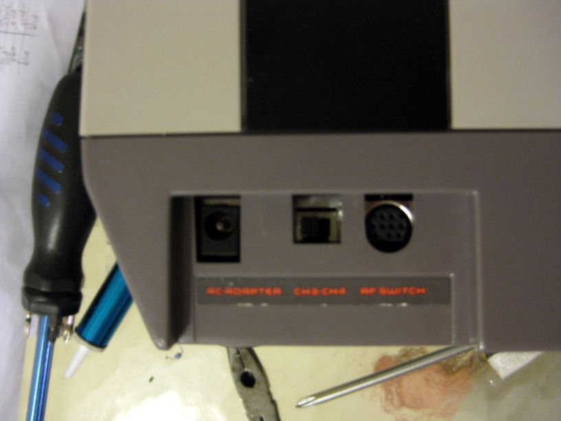
So everything came out the way I wanted, where the NES doesn't look modified. Palette is set to the ch3-ch4 switch, and the minidin looks mostly stock and feeds both rgb and s- video. I had to mount it upside down, which is a little awkward, to make things fit better, and cause I didn't feel like hacking away at the chassis.
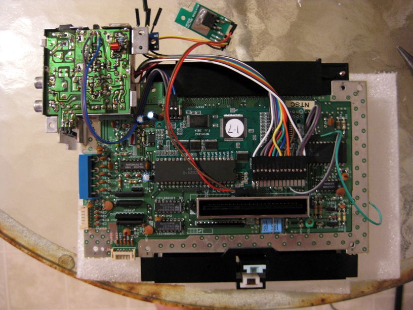
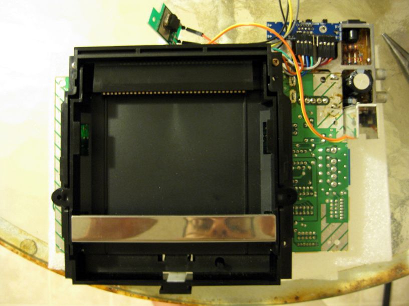
Apologies for the blurry photos. My camera is crap.
Apologies for the blurry photos. My camera is crap.
Last edited by Einzelherz on Tue Aug 12, 2014 5:39 am, edited 1 time in total.
-
daskrabs
- Posts: 257
- Joined: Sat Oct 01, 2011 1:05 pm
- Location: Philly Area
Re: NESRGB board available now
Finally got my AV Fami modded and working 100%. Just wanted give a summary of events for those that are considering doing the mod themselves, especially those that are not the best at soldering and do not have pro soldering/desoldering gear.
Gear:
Radio Shack Desoldering tool ($15) (mostly fail)
Radio Shack soldering iron ($25) (mostly fail)
M-Line Mark V pro-grade soldering station (~$100) (used with success)
Events:
-Bought a NESRGB, successfully desoldered AVFC PPU with cheap tools
-soldered the adapter board in backwards
-continued, thinking this was not a problem
-Upon completing mod, video/audio failed
-Desoldered NESRGB, destroyed adapter board, ordered new one
-After new adapter came in, resoldered everything correct
-Fired it up, worked. Yay.
-Tried a different game, FAIL. Black screen and loud buzz
-Tested AV Fami w/ stock PPU and no NESRGB, fail. Black screen and loud buzz
-Replaced PPU and CPU, stock AVFC worked again. I fried both chips on the AVFC (see below)
-Deciding not to work with obviously cursed hardware, bought a new AVFC and NESRGB
-Did everything correctly. Fired up, worked.
-Closed it up. Tested all games. All worked. Double Yay!
Afterthoughts:
-While it is possible to use cheap, AKA Radio Shack soldering and desoldering irons, I cannot recommend them because they simply don't get hot enough to melt the original solder on the PCB and remove the PPU. When I used pro gear ($100+), everything was tits.
-If you knock the NESRGB out of the socket after completing the mod, and you turn on your NES/FC, you might fry your CPU and PPU. This happened to me.
-The hardest part for an amateur is definitely desoldering the PPU. TAKE YOUR TIME. Add solder to pins that wont desolder, and try again. If that doesn't work, borrow/buy a higher temperature tool. Breaking the chip sucks ass. Again, happened to me.
-Follow the steps on Tim's site CLOSELY. Don't be an asshole and solder things in the wrong order/backwards like me.
-Using NESRGB composite. In some ways, looks better than stock, some ways worse. I say use stock after having seen both. At least for AVFC.
-Improved palette looks best of the 3 IMHO.
-I'm going to test my 1st NESRGB again, as well as my 1st AVFC for lingering effects. Probably sell them for either parts or working depending on outcome.
-In the end, it was worth the trouble. Learned a lot. Video quality on a PVM is tits.
-
ms06fz
- Posts: 103
- Joined: Mon Apr 14, 2014 8:48 pm
Re: NESRGB board available now
Nice work, thanks for posting pictures. (I'd meant to ask you to do that, 'cause I wanted to see how it worked out, mounting the mini-DIN in place of the RF jack)Einzelherz wrote:So everything came out the way I wanted, where the NES doesn't look modified. Palette is set to the ch3-ch4 switch, and the minidin looks mostly stock and feeds both rgb and s- video.
When I was toying with this idea I came to the conclusion that it wouldn't work, because it seemed the mini-DIN cable wouldn't be able to plug into the connector properly... But it's working out for you, I guess?
-
ms06fz
- Posts: 103
- Joined: Mon Apr 14, 2014 8:48 pm
Re: NESRGB board available now
I did my first install with a soldering iron and a piston-style desoldering pump... Yeah that wasn't fun. Too hard to effectively apply heat and then get suction before the solder cooled. (Usually it meant heating one side of the board and using suction on the other - but on the NES front-loader that's complicated by the presence of the expansion connector.)daskrabs wrote:Finally got my AV Fami modded and working 100%. Just wanted give a summary of events for those that are considering doing the mod themselves, especially those that are not the best at soldering and do not have pro soldering/desoldering gear.
Gear:
Radio Shack Desoldering tool ($15) (mostly fail)
Radio Shack soldering iron ($25) (mostly fail)
M-Line Mark V pro-grade soldering station (~$100) (used with success)
For my second install (my precious AV Famicom!) I got a desoldering iron very similar to this one - I found it to be quite effective. So I don't think it's necessary to go for a $100 desoldering station to get good results for a job like this. Though I'm sure it helps.
-
Einzelherz
- Posts: 1280
- Joined: Wed Apr 09, 2014 2:09 am
Re: NESRGB board available now
It's a tight fit, but nothing is interfering. The jack needs to be nearly perfectly centered and in the case of the cable I used, as low as possible.ms06fz wrote:Nice work, thanks for posting pictures. (I'd meant to ask you to do that, 'cause I wanted to see how it worked out, mounting the mini-DIN in place of the RF jack)Einzelherz wrote:So everything came out the way I wanted, where the NES doesn't look modified. Palette is set to the ch3-ch4 switch, and the minidin looks mostly stock and feeds both rgb and s- video.
When I was toying with this idea I came to the conclusion that it wouldn't work, because it seemed the mini-DIN cable wouldn't be able to plug into the connector properly... But it's working out for you, I guess?
It took some time to get it oriented--basically soldering small joints on the RF box, screwing it back into the NES, checking, and repeat. Then when it was close enough (kinda crooked in two planes) I just solder-welded it on.
-
joeblade

- Posts: 41
- Joined: Tue Oct 11, 2005 5:44 pm
Re: NESRGB board available now
Been keeping tabs on restock of the boards for awhile now but nothing as yet...any idea when these will be available to buy again?
"Have you ever retired a human by mistake"
-
tacoboy42
- Posts: 30
- Joined: Wed Jul 23, 2014 6:51 pm
Re: NESRGB board available now
They are up now and was able to order one, I was waiting as well.joeblade wrote:Been keeping tabs on restock of the boards for awhile now but nothing as yet...any idea when these will be available to buy again?
-
LaC
- Posts: 38
- Joined: Fri Feb 01, 2013 12:35 am
- Location: Champaign, IL
Re: NESRGB board available now
So I'm having a problem with a NESRGB I installed on a Twin Fami. I don't get any video (rgb, or s-video, or composite). Just a quick flash when it boots up.
Also I only here a few notes played slowly from the startup screen. Games do the same thing, just a few notes played slowly, but you can tell it's part of the original song.
I feel some trace has been cut or lifted during the process. But I've scanned the pcb pretty good and everything looks ok...
Anyone have any idea what I might focus on to find a fix?
-
eightbitminiboss
- Posts: 450
- Joined: Mon Sep 17, 2012 9:01 pm
Re: NESRGB board available now
I'd check in and around the PPU area closely.LaC wrote:So I'm having a problem with a NESRGB I installed on a Twin Fami. I don't get any video (rgb, or s-video, or composite). Just a quick flash when it boots up.
Also I only here a few notes played slowly from the startup screen. Games do the same thing, just a few notes played slowly, but you can tell it's part of the original song.
I feel some trace has been cut or lifted during the process. But I've scanned the pcb pretty good and everything looks ok...
Anyone have any idea what I might focus on to find a fix?
-
Monstermug

- Posts: 404
- Joined: Thu Mar 31, 2011 7:58 pm
- Location: London, UK
Re: NESRGB board available now
Is there an idiot's guide to installing NESRGB board in a top loader anywhere? Something a little more detailed perhaps? No offense to Tim but the instructions on his website have bits missing. I started reading through this thread but 100 pages is a lot of shit to shift through. I mean I don't even know which socket the ppu is supposed to go in to in the version 1.7 nesrgb board. Also it states not to use a socket for the PPU chip yet I find a socket in the kit.
Here is the guide I am refering to btw: http://etim.net.au/nesrgb/installation-nes/
Stage II. Prepare NESRGB board.
2. Insert pin headers into NES motherboard. Solder.
4. Insert the pin headers (shorter part goes into the board) and solder only the end pins of each. (wtf I just soldered it to the motherboard) !!!
If you did this as per instructions, there is no way you going to be able to solder the PPU to the NESRGB board!
Stage III. Solder wires.
1. Cut, strip, and tin lots of wires to a length of 25mm. One length fits all. Use thicker wires for power and ground connections.
(wtf 25mm is like 2.5cm) That wont even reach past the NESRGB board.
Also I think he needs to make it clearer that the VIN on the voltage regulator should go to the VIN on the NES voltage regulator. I worked it out by looking at the pics.
It might be a good idea to state which pin is 1 and 2 on the CPU? Some idiot may not know. Maybe state that using the pins on the two resisters closes may be a better alternative?
Finally perhaps on the installation guide, put a note saying that if no palette is selected (i.e.) if no switch is installed only composite signals are passed through as if the NESRGB board wasn't even installed.
It seems the easiest part was removing the PPU chip! I did that in like 3 minutes and it came out perfect! lol
-
ApolloBoy

- Posts: 939
- Joined: Sat Jan 28, 2012 7:17 pm
Re: NESRGB board available now
LOL, really? It should be very straightforward just by looking at the instructions! Also, the warning about using a PPU socket is for the front loader as there isn't enough space to have the PPU socketed (I installed an NESRGB in my front loader a few weeks back and confirmed this). With the top loader, AV Famicom and Twin Famicom there's plenty of room to have the PPU socketed.Monstermug wrote:I mean I don't even know which socket the ppu is supposed to go in to in the version 1.7 nesrgb board. Also it states not to use a socket for the PPU chip yet I find a socket in the kit.
-
Monstermug
- Posts: 404
- Joined: Thu Mar 31, 2011 7:58 pm
- Location: London, UK
Re: NESRGB board available now
Version 1.7 looks different to the version shown in the instructions.ApolloBoy wrote:LOL, really? It should be very straightforward just by looking at the instructions! Also, the warning about using a PPU socket is for the front loader as there isn't enough space to have the PPU socketed (I installed an NESRGB in my front loader a few weeks back and confirmed this). With the top loader, AV Famicom and Twin Famicom there's plenty of room to have the PPU socketed.Monstermug wrote:I mean I don't even know which socket the ppu is supposed to go in to in the version 1.7 nesrgb board. Also it states not to use a socket for the PPU chip yet I find a socket in the kit.
Also this!
7. Insert PPU and solder into place on the board. Do not put the PPU into a socket as there is not enough space (height) available for it to fit. Double check to make sure the PPU is in the right way around!
I must admit though, the instructions to make the scart lead was exceptional! I love the pcb that fits inside the scart and on the 9 pin din. I was dreading making the scart bit the most as those little pins are so annoying to solder wires onto, but those pcbs made it a walk in the park.
-
Einzelherz
- Posts: 1280
- Joined: Wed Apr 09, 2014 2:09 am
Re: NESRGB board available now
I just looked at the pictures of all of the finished installs and set the riser pins and PPU to match.
-
mufunyo
- Posts: 176
- Joined: Thu Jun 19, 2008 11:45 am
Re: NESRGB board available now
Just to clear this up once and for all, this is the amount of clearance you have in an AV famicom / top loader NES if you socket the PPU:Monstermug wrote:Is there an idiot's guide to installing NESRGB board in a top loader anywhere? Something a little more detailed perhaps? No offense to Tim but the instructions on his website have bits missing. I started reading through this thread but 100 pages is a lot of shit to shift through. I mean I don't even know which socket the ppu is supposed to go in to in the version 1.7 nesrgb board. Also it states not to use a socket for the PPU chip yet I find a socket in the kit.

-
ms06fz
- Posts: 103
- Joined: Mon Apr 14, 2014 8:48 pm
Re: NESRGB board available now
I agree, it's a bit unclear. But there's a few indicators:Monstermug wrote:Is there an idiot's guide to installing NESRGB board in a top loader anywhere? Something a little more detailed perhaps? No offense to Tim but the instructions on his website have bits missing. I started reading through this thread but 100 pages is a lot of shit to shift through. I mean I don't even know which socket the ppu is supposed to go in to in the version 1.7 nesrgb board.
1: One of the two 5V pins is labeled "PPU 5V" - this pin connects to the PPU.
2: On recent versions of the board the thru-holes for the PPU are bigger than the ones that connect to the main board, to make it easier to desolder and remove a PPU you've installed in a NESRGB.
Basically, the 40 pin footprint farther away from the edge of the board goes to the PPU. The set closer to the edge of the board goes to the NES main board.
The kit includes a lot of parts that you may or may not use depending on the particulars of your install. Some of it comes down to preference, some of it depends on what type of system you're installing on, etc. The question of whether to mount a socket for the PPU is mostly a matter of whether you have space for it.Also it states not to use a socket for the PPU chip yet I find a socket in the kit.
Let me know if you have any other issues along the way, maybe I can help.
-
LXXero
- Posts: 3
- Joined: Sat Aug 23, 2014 10:08 am
Re: NESRGB board available now
Hi all, first post here, but I've been following the thread since I just got an nesrgb and installed it. Actually, it's working great, no problems so far with how it's setup now. I've got it wired up to a female scart socket while I wait for my 3d printed multi-av connector to arrive for my toploader, and I'm planning on redoing it a bit after that arrives. That said, there's a few more things I wanted to do and I wasn't really sure about them.
What's the current/best method for wiring up expansion audio in a top loader? I recall discussion regarding having to solder onto a resistor on the nesrgb board somewhere? The other end of it, I'm even less sure about, especially for the top loader, I've only been finding av famicon instructions.
I recall someone mentioning the idea of putting a resistor on the board to work with the nes everdrive n8's volume level out of the box, and then putting an additional resistor into the nes->famicon adapter to match the actual famicon cartridge audio output. I rather like this idea, any more details as to the resistor values to make that work?
I also saw some mixed opinions as to whether removing the 220uf caps is really necessary when using a multiav ->scart cable that has them already, is there a consensus on that? I am going to be using cables that definitely do have the caps, and I'm using that cable with my other systems so I don't want to mod the cable, but I've seen people saying it doesn't really matter.
-
Edenal
- Posts: 2
- Joined: Sat Aug 23, 2014 2:45 pm
Re: NESRGB board available now
Sorry if this is the wrong place to ask a question about my issues with installing the NESRGB.
(To start of, I did confirm that the NES was in fully working order before starting)
The problem I'm having is that I do not get a working picture on with through the DIN8.
- On my PVM, I get no sync. Just a rolling picture, colors are fine though.
- On my LCD, I get no picture or audio at all. Except for a few frames after starting the console, I get a flash och audio + video, then it's gone.
- I hooked up the NES to a XRGB-mini. Same issue.
S-video is working perfectly. As shown in this picture:
https://drive.google.com/file/d/0B5EWxs ... sp=sharing
*** Note that it's hooked up to my PC monitor through the XRGB-mini
The original composite from the NES looks very strange. I'm no expert, but I think it's luma only? This output worked fine before I removed the PPU. Maybe I broke or shorted something?
https://drive.google.com/file/d/0B5EWxs ... sp=sharing
*** Note that it's hooked up to my PC monitor through the XRGB-mini
Pallet switch works fine. I've shorted Jumper 5. (Not that it made any difference)
I've followed the guide on Tim's site. And I'm just clueless in this matter. I hope you can help me shed some light on my issue!
-
Skips
- Posts: 404
- Joined: Tue Oct 22, 2013 3:03 am
Re: NESRGB board available now
Well I don't know about you guys but it fits perfectly fine in my front loader with a socket. Here is one I recently did for myself. This is going to be the last system I do for a good long time. I've done enough of these mods now that I can say that it is boring as hell now. I included a couple pictures of it running in component video through my capture device as well (click for full view). I also wired up the regulator this time just because why the hell not.
** Updated With Better Pictures**


** Updated With Better Pictures**
Last edited by Skips on Mon Aug 25, 2014 4:08 pm, edited 1 time in total.
I am no longer taking free or paid modding projects, please do not contact me asking for my services. Thanks  .
.
-
Sixfortyfive
- Posts: 212
- Joined: Mon Sep 17, 2007 6:31 am
Re: NESRGB board available now
Test all of the following:Edenal wrote:I've followed the guide on Tim's site. And I'm just clueless in this matter. I hope you can help me shed some light on my issue!
- composite video from NESRGB
- original composite video passthrough from PPU
- RGB using composite video as sync
- RGB using CS# for sync
If you're consistently running into issues when using the NESRGB's composite video output specifically, the capacitor for that output might be bad. This happened to me as well, so I'm wondering if it's somewhat common.
If anything else is also not functioning correctly, then I'm not sure.
-
Pasky

- Posts: 699
- Joined: Mon Oct 21, 2013 3:58 am
Re: NESRGB board available now
Is the top loader adapter board necessary for the Twin Famicom install?
-
Skips
- Posts: 404
- Joined: Tue Oct 22, 2013 3:03 am
Re: NESRGB board available now
No, twin fami has its own adapter. The Kit goes underneath the Famicom PCB in the Twin Famicom.Pasky wrote:Is the top loader adapter board necessary for the Twin Famicom install?
I am no longer taking free or paid modding projects, please do not contact me asking for my services. Thanks .
-
Pasky
- Posts: 699
- Joined: Mon Oct 21, 2013 3:58 am
Re: NESRGB board available now
Any pics of a twin famicom install? Gonna do this next weekend on mine.
-
Skips
- Posts: 404
- Joined: Tue Oct 22, 2013 3:03 am
Re: NESRGB board available now

I am no longer taking free or paid modding projects, please do not contact me asking for my services. Thanks .
-
Skips
- Posts: 404
- Joined: Tue Oct 22, 2013 3:03 am
Re: NESRGB board available now
Just some more pics of the RGB NES running through the CVS287 component converter to my capture card. Nice and Crystal clear even for component video. Palettes being used vary. I get asked a lot how stuff looks so i figured id post this too.


I am no longer taking free or paid modding projects, please do not contact me asking for my services. Thanks .
-
eightbitminiboss
- Posts: 450
- Joined: Mon Sep 17, 2012 9:01 pm
Re: NESRGB board available now
In case you want to swap out the DIN Connector: http://shmups.system11.org/viewtopic.ph ... 1#p1030961Pasky wrote:Any pics of a twin famicom install? Gonna do this next weekend on mine.
-
The_Atomik_Punk!
- Posts: 110
- Joined: Mon Mar 10, 2014 3:47 pm
- Location: Toronto, Canada
Re: NESRGB board available now
Thought I'd post here instead of starting a new thread. Is anyone here accepting commissions to install Tim's RGB kit at the moment? Does anyone have any recommended modders? I've asked around and found most of the big names on here either too busy, or disinterested with the prospect. I'm looking to get my NES Frontloader modded, or possibly a Famicom/ AV Famicom if that is preferred. If anyone here is looking for a commission, please PM me, as I'd like to get a kit installed ASAP (I'm in Toronto, Canada).
-
mufunyo
- Posts: 176
- Joined: Thu Jun 19, 2008 11:45 am
Re: NESRGB board available now
AV Famicoms are probably the easiest to mod, since you don't need an external regulator, you don't have to drill any holes and can straight up use the multi-out connector. They're also the most robust and versatile, considering they don't have a lockout chip and don't require any modifications for aux audio.The_Atomik_Punk! wrote:or possibly a Famicom/ AV Famicom if that is preferred.
-
The_Atomik_Punk!
- Posts: 110
- Joined: Mon Mar 10, 2014 3:47 pm
- Location: Toronto, Canada
Re: NESRGB board available now
Sounds good to me, I'd want to use the system with a Retro_console_accessories SNES SCART cable, so the multi-out of the AV Famicom would make the install more simplified- thanks for the suggestion. If anyone is interested in a commission, I'm looking to send an AV Famicom to have one of Tim's RGB kits installed, PM me.mufunyo wrote:AV Famicoms are probably the easiest to mod, since you don't need an external regulator, you don't have to drill any holes and can straight up use the multi-out connector. They're also the most robust and versatile, considering they don't have a lockout chip and don't require any modifications for aux audio.The_Atomik_Punk! wrote:or possibly a Famicom/ AV Famicom if that is preferred.
-
Skips
- Posts: 404
- Joined: Tue Oct 22, 2013 3:03 am
Re: NESRGB board available now
If its an AV Famicom I will do ONE more. I shot you an e-mail.The_Atomik_Punk! wrote:Sounds good to me, I'd want to use the system with a Retro_console_accessories SNES SCART cable, so the multi-out of the AV Famicom would make the install more simplified- thanks for the suggestion. If anyone is interested in a commission, I'm looking to send an AV Famicom to have one of Tim's RGB kits installed, PM me.mufunyo wrote:AV Famicoms are probably the easiest to mod, since you don't need an external regulator, you don't have to drill any holes and can straight up use the multi-out connector. They're also the most robust and versatile, considering they don't have a lockout chip and don't require any modifications for aux audio.The_Atomik_Punk! wrote:or possibly a Famicom/ AV Famicom if that is preferred.
I am no longer taking free or paid modding projects, please do not contact me asking for my services. Thanks .