There sure is: https://www.videogameperfection.com/201 ... de-review/Woozle wrote:Is there a way to get pure digital audio from snes?
Let's talk SNES HDMI (analog based)
-
ApolloBoy

- Posts: 939
- Joined: Sat Jan 28, 2012 7:17 pm
Re: Let's talk SNES HDMI (analog based)
-
Woozle
- Posts: 232
- Joined: Wed Jun 24, 2015 8:27 pm
- Location: Florida
Re: Let's talk SNES HDMI (analog based)
That's a good idea, I'll look into that IC. Maybe I can achieve a similar function in FPGA logic.
-
Seraphic
- Posts: 492
- Joined: Fri Mar 19, 2010 1:46 pm
Re: Let's talk SNES HDMI (analog based)
That digital audio mod outputs 32khz/16bit audio. That can cause compatibility issues as it is not widely supported it today's hardware.Woozle wrote:That's a good idea, I'll look into that IC. Maybe I can achieve a similar function in FPGA logic.
There is also the below board that triples the khz to a much more supported 96kkz/24bit digital audio stream.
https://oshpark.com/shared_projects/5NrKCmY9
-
Woozle
- Posts: 232
- Joined: Wed Jun 24, 2015 8:27 pm
- Location: Florida
Re: Let's talk SNES HDMI (analog based)
If I'm doing straight digital audio to FPGA, I could do any retiming in FPGA logic and pad audio data to 24-bit. Then again if the chip really simplifies things then I would go ahead and use that.
-
Seraphic
- Posts: 492
- Joined: Fri Mar 19, 2010 1:46 pm
Re: Let's talk SNES HDMI (analog based)
The problem is more the "khz" then the "bit".Woozle wrote:If I'm doing straight digital audio to FPGA, I could do any retiming in FPGA logic and pad audio data to 24-bit. Then again if the chip really simplifies things then I would go ahead and use that.
32khz is like 240p, it's just not widely supported anymore.
I made an account on their page once to check out price for boards, link below (minimum of three)
https://s13.postimg.org/3nnkcfvp3/Untitled.png
-
Woozle
- Posts: 232
- Joined: Wed Jun 24, 2015 8:27 pm
- Location: Florida
Re: Let's talk SNES HDMI (analog based)
Wouldn't that just be a matter of clocking sound data into a buffer at the SNES audio rate and then reading it at 96khz in the FPGA for the audio output?
-
RGB32E

- Posts: 1400
- Joined: Thu Nov 05, 2009 12:50 am
Re: Let's talk SNES HDMI (analog based)
A CS8406 circuit doesn't really simplify things. Digital audio to the FPGA is the way to go. This is what the UltraHDMI does. That said, there are a few scenarios, such as the Super GameBoy and MSU-1/SD2SNES, where cartridge audio (two pins on the card slot) are used, so a two channel ADC would be required as well to support all scenarios. I SPDIF modded (coax... optical is jitter prone) years ago and love the results.Woozle wrote:If I'm doing straight digital audio to FPGA, I could do any retiming in FPGA logic and pad audio data to 24-bit. Then again if the chip really simplifies things then I would go ahead and use that.
The mod kit plugged above is Borti's OSHPark shared project that is being assembled and resold by someone in the UK. The actual technical data can be found here.
If you're reclocking the SNES with an accurate and low jitter clock the "slightly off spec" 32kHz should be corrected.
EDIT: (CS8604 -> CS8406
Last edited by RGB32E on Sat Nov 05, 2016 5:38 pm, edited 1 time in total.
-
RGB32E
- Posts: 1400
- Joined: Thu Nov 05, 2009 12:50 am
Re: Let's talk SNES HDMI (analog based)
32kHz is technically a HDMI supported sampling rate. While most all receivers accept 96kHz PCM over HDMI, very few TVs will sink it. I know the higher end current model Sony UHDTVs support 96kHz, but haven't found any other brands that do.Woozle wrote:Wouldn't that just be a matter of clocking sound data into a buffer at the SNES audio rate and then reading it at 96khz in the FPGA for the audio output?
As mentioned above, if you have the appropriate master clock provided by the FPGA I'd imagine the "slightly off spec" 32kHz signal from the SNES could be corrected to "standard".
-
Seraphic
- Posts: 492
- Joined: Fri Mar 19, 2010 1:46 pm
Re: Let's talk SNES HDMI (analog based)
Listen to RGB32E, I was just making suggestions. While he the technical knowledge to really help you.Woozle wrote:Wouldn't that just be a matter of clocking sound data into a buffer at the SNES audio rate and then reading it at 96khz in the FPGA for the audio output?
Good luck with your project though! I for one would be interested in a HDMI mod for the SNES.
-
Guspaz

- Posts: 3242
- Joined: Tue Oct 06, 2015 7:37 pm
- Location: Montréal, Canada
Re: Let's talk SNES HDMI (analog based)
You might not need to modify the multi AV port to get the clock out of the SNES, the expansion port on the bottom has a clock signal that is reported to be the PPU dot clock.
-
Woozle
- Posts: 232
- Joined: Wed Jun 24, 2015 8:27 pm
- Location: Florida
Re: Let's talk SNES HDMI (analog based)
That's a good idea, but I'm doing this on a snes mini. Not sure if the expansion pins are still on the pcb.
I think I'm just going to either use the clock on cart pin 1 or remove the crystal and provide a ~21Mhz clock from the fpga.
I think I'm just going to either use the clock on cart pin 1 or remove the crystal and provide a ~21Mhz clock from the fpga.
-
RGB0b
- Posts: 543
- Joined: Wed Dec 05, 2012 1:52 pm
Re: Let's talk SNES HDMI (analog based)
Maybe an internal mod for the Mini and an external for the big SNES' that plug into the bottom port? That's probably not cost-effective at all, but any time you can have a product like this that requires no modding at all, it opens itself up to a much wider audience.Guspaz wrote:You might not need to modify the multi AV port to get the clock out of the SNES, the expansion port on the bottom has a clock signal that is reported to be the PPU dot clock.
-
Woozle
- Posts: 232
- Joined: Wed Jun 24, 2015 8:27 pm
- Location: Florida
Re: Let's talk SNES HDMI (analog based)
I'm working on a combined pcb for the ADCs and fpga, it's not far from done. This board will only need 7 solder points (red, green, blue, csync, clock, power, Ground) to install. I'm trying to make it so it mounts around the screw post under the mini pcb and the HDMI is on an extended piece of pcb so it's accessible externally. If it works out like planned the install difficulty would be comparable to the ths7374 amp mods. But this doesn't include sound, that's something I'll have to look at later.
I need to figure out the RGB analog signal level stuff because currently I'm using RGB signals from the ths7314 mod. I'm not sure if an amplifier is necessary before the ADCs or if I can just grab it from the SNES pcb. My ADCs have 75ohm inputs, if that matters.
The expansion port wouldn't allow me to re-clock the SNES which I think is a good option to have and my initial design will be based around having control over timing. I'll definitely look into other SNES models though. A big reason for working on the mini is that I already have two.
-
paulb_nl
- Posts: 341
- Joined: Sat Feb 20, 2016 5:05 pm
Re: Let's talk SNES HDMI (analog based)
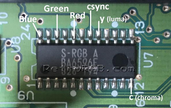
If you need amplified signals then you can just grab them from the S-RGB encoder. Csync, power and ground are right next to the RGB pins.Woozle wrote:I need to figure out the RGB analog signal level stuff because currently I'm using RGB signals from the ths7314 mod. I'm not sure if an amplifier is necessary before the ADCs or if I can just grab it from the SNES pcb. My ADCs have 75ohm inputs, if that matters.
-
Woozle
- Posts: 232
- Joined: Wed Jun 24, 2015 8:27 pm
- Location: Florida
Re: Let's talk SNES HDMI (analog based)
Should I put a 75ohm series resistor on the encoder output close to the encoder? My ADC expects a 75ohm source impedance.
I realized I'm using an incorrect reference voltage level (using the one from ADC08100 datasheet). Right now my input voltage range is 0-1.5v, need to change that to 0-0.7v I would think. Just two resistors to change at each ADC. Since the voltage regulator which is the input to the reference voltage divider (ideally 3.3v) outputs ~3.13v, the two resistors should be 174ohm (pull-up) and 51ohm (pull-down) to give a reference voltage of about 0.709v. Both resistances are available at digikey in 0402 packages. Different resistor values can be used if a little more headroom is needed on the input voltage range.
I remember reading something about the SNES having incorrect voltage levels + overshoot for the analog RGB signals. Is the best way to fix that resistors from rgb signals to ground (1.2k?)? Then for the overshoot, use Borti's method of lifting the PPU pin and putting a series resistor on the VDD line?
-
paulb_nl
- Posts: 341
- Joined: Sat Feb 20, 2016 5:05 pm
Re: Let's talk SNES HDMI (analog based)
Yes normally the RGB mod is with 75ohm resistors to the multi out.Woozle wrote:Should I put a 75ohm series resistor on the encoder output close to the encoder? My ADC expects a 75ohm source impedance.
I remember reading something about the SNES having incorrect voltage levels + overshoot for the analog RGB signals. Is the best way to fix that resistors from rgb signals to ground (1.2k?)? Then for the overshoot, use Borti's method of lifting the PPU pin and putting a series resistor on the VDD line?
If you use Borti's method then the overshoot and voltage levels are corrected. Then you don't need the resistors to ground.
-
Woozle
- Posts: 232
- Joined: Wed Jun 24, 2015 8:27 pm
- Location: Florida
Re: Let's talk SNES HDMI (analog based)
Alright, just finished the first draft for the combined ADC + FPGA pcb. https://oshpark.com/shared_projects/MRpSJ9A0
This board will wire to the SNES video encoder. It needs 5v, ground, red, green, blue, and csync from the SNES and a clock line from the board to the SNES crystal. There are also plenty of spare I/O pads for handling the audio.
After I look this board over for errors I'll order a set on oshpark and get it assembled in the next month or two.
As far as the noise...it turns out when the ADCs first power on, there is almost no noise in the image. After about a minute the noise is present. It looks really good so far before the noise sets in https://imgur.com/a/PWKr8. Right now I'm taking the analog RGB signals from a multi-out->scart->BNC setup, is it possible the noise is a DC level on the cable?
When the noise is gone, the image is a bit darker. I'm thinking it's due to the ADC reference voltage being set to 1.5v by mistake, putting my peak white value at ~128 on the ADC digital output. It should look a lot nicer with the correct reference level.
-
borti4938
Re: Let's talk SNES HDMI (analog based)
Woozle wrote:Maybe it would be best to remove the SNES oscillator and clock it with the fpga?
I hope you do not think about clocking the SNES over pin 1 of the cartridge edge connector!Woozle wrote: I soldered a wire to pin 1 of the SNES cartridge connector which is a 21mhz clock signal. Dividing it by 4 in the fpga gave me a proper pixel clock to sample with.
As the other people mentioned: it is possible. But I want to interrupt here: there are some people out there loving the MSU-1 sound hacks to several games and playing them on the sd2snes. This sound is digital-to analog converted on the sd2snes and mixed to the analogue audio channels of the SNES. So you will NEVER have them digitalized on the SNES mainboard. (Same with the Super Gameboy in-game sound)Woozle wrote: Integrating audio over HDMI is something I'll look into, I just don't really know how that works at the moment (audio sampling chip, I2S, putting it in HDMI data). Is there a way to get pure digital audio from snes?
So a "better" way would be to place an ADC here, too!
The problem you have here with your approach is that the Vpp level depends on the load to the MultiAV. This means it varies depending on you have a RGB cable plugged to a TV or not. Or in other words: your levels are either correct for your HDMI board OR the RGB picture but never both.Woozle wrote:Should I put a 75ohm series resistor on the encoder output close to the encoder? My ADC expects a 75ohm source impedance.
I realized I'm using an incorrect reference voltage level (using the one from ADC08100 datasheet). Right now my input voltage range is 0-1.5v, need to change that to 0-0.7v I would think. Just two resistors to change at each ADC. Since the voltage regulator which is the input to the reference voltage divider (ideally 3.3v) outputs ~3.13v, the two resistors should be 174ohm (pull-up) and 51ohm (pull-down) to give a reference voltage of about 0.709v. Both resistances are available at digikey in 0402 packages. Different resistor values can be used if a little more headroom is needed on the input voltage range.
I suggest you to go a step back in the SNES signal chain an take the RGB (+ sync) signals directly out of the S-CPUN and amplify them separated to the MultiAV ouput... I quickly made a sketch how I would realize it:
Spoiler

Yes, the S-CPUN outputs to high levels for RGB and also overshoots them on sharp edges.Woozle wrote:I remember reading something about the SNES having incorrect voltage levels + overshoot for the analog RGB signals. Is the best way to fix that resistors from rgb signals to ground (1.2k?)? Then for the overshoot, use Borti's method of lifting the PPU pin and putting a series resistor on the VDD line?
A way to fix the Vpp is to add the three 1.2k resistors parallel to R6, R7 and R8. This doesn't change anything on the overshoots. (not my suggestion; this was developed by Ultron and the AG-community)
An alternative (and in my point of view better) way is lift pin 155 of the S-CPUN and reconnect the pin to +5V over a 20 ohm resistor. This corrects the Vpp levels and also reduces the overshoots, dramatically.
-
Woozle
- Posts: 232
- Joined: Wed Jun 24, 2015 8:27 pm
- Location: Florida
Re: Let's talk SNES HDMI (analog based)
I'm only using cart1 pin for receiving the clock signal, if I try to wire directly to crystal it puts too much load on it and doesn't work. I plan to remove the crystal and provide a clock from fpga to the crystal pcb pads. I also need to include a small circuit to bring my clock from fpga up to 5v. I'm still looking for the best location to place my clock, any suggestions are welcome.
I want to include an ADC for msu-1 audio, but that will be something I look at later.
That's a good point about the need for an amplifier. There's also another reason an amplifier is necessary. The Minimum range for the analog input on the ADC is 1-volt, so I would need to amplify the video otherwise Ill lose some brightness. I could always just set the ADC range to ~0.8v and see if it still works.
Are there vias that I can grab the video signals from? Or would it require soldering to CPU?
Thanks for the input Borti!
-
borti4938
Re: Let's talk SNES HDMI (analog based)
Keep in mind that the S-CPUN needs a different value for X1 if this chip runs in PAL mode (and also PAL units in general). I just wanted to mention that for future finalization steps...Woozle wrote:I'm only using cart1 pin for receiving the clock signal, if I try to wire directly to crystal it puts too much load on it and doesn't work. I plan to remove the crystal and provide a clock from fpga to the crystal pcb pads. I also need to include a small circuit to bring my clock from fpga up to 5v. I'm still looking for the best location to place my clock, any suggestions are welcome.
I guess that 3.3V could be enough for the S-CPUN. There is a buffer behind the clock input (pin 9) anyway. So just try it out
If this doesn't work you may use a SN74LV1T126DBVR for level shifting.
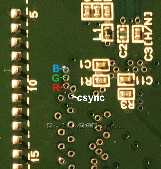
You can use the same vias as RetroRGB.com shows here:Woozle wrote: Are there vias that I can grab the video signals from? Or would it require soldering to CPU?
Spoiler


You are welcomeWoozle wrote: Thanks for the input Borti!
-
Woozle
- Posts: 232
- Joined: Wed Jun 24, 2015 8:27 pm
- Location: Florida
Re: Let's talk SNES HDMI (analog based)
Is there any way for the ths7374 to provide gain? Based on its internal diagram it doesn't look like I could just add a feedback resistor.
I'm already using the ADCs out of spec, it works but maybe providing some gain to the video signal to bring it into the ADCs range would yield better results (or not )
)
Do you think it's worth the circuit cost/area to use a precision reference circuit (using opamps versus resistors)? SNES games tend to be fairly high contrast, I'm worried it might cause variance on the ADC reference voltage level.
I'm already using the ADCs out of spec, it works but maybe providing some gain to the video signal to bring it into the ADCs range would yield better results (or not
Do you think it's worth the circuit cost/area to use a precision reference circuit (using opamps versus resistors)? SNES games tend to be fairly high contrast, I'm worried it might cause variance on the ADC reference voltage level.
-
borti4938
Re: Let's talk SNES HDMI (analog based)
The THS7374 has build in 6dB gain; in fact this means that the output Vpp is doubled compared to the input.
-
Woozle
- Posts: 232
- Joined: Wed Jun 24, 2015 8:27 pm
- Location: Florida
Re: Let's talk SNES HDMI (analog based)
Whoops...right in the title of the datasheet.
Does the ths7374 double the RGB from 0.7v -> 1.4v which is cut back in half due to the 75ohm source/sink termination? So by the time it gets to my 75ohm terminated ADC, wouldn't it be right back at 0.7v?
Does the ths7374 double the RGB from 0.7v -> 1.4v which is cut back in half due to the 75ohm source/sink termination? So by the time it gets to my 75ohm terminated ADC, wouldn't it be right back at 0.7v?
-
Woozle
- Posts: 232
- Joined: Wed Jun 24, 2015 8:27 pm
- Location: Florida
Re: Let's talk SNES HDMI (analog based)
Made a smaller board with more I/O pads available, it should be general enough to work for multiple consoles. Has enough I/O for the SNES digital audio, digital audio from an ADC (still need to make audio ADC circuit), and SNES controller data/latch/clock.
I'll order this pcb today or tomorrow after I look it over some more, then I'll assemble it and get to testing.
https://oshpark.com/projects/0Jm7hIjr
I'll order this pcb today or tomorrow after I look it over some more, then I'll assemble it and get to testing.
https://oshpark.com/projects/0Jm7hIjr
Last edited by Woozle on Wed Nov 16, 2016 10:22 pm, edited 5 times in total.
-
Guspaz
- Posts: 3242
- Joined: Tue Oct 06, 2015 7:37 pm
- Location: Montréal, Canada
Re: Let's talk SNES HDMI (analog based)
I'll admit I'm a complete neophyte, but possible error:
http://i.imgur.com/gxGcuSA.png
See red circled area. Trace goes through via to the other side of the board, but doesn't seem to be trying to jump over anything, nor does it open access to the ground plane. Missing trace, maybe?
http://i.imgur.com/gxGcuSA.png
See red circled area. Trace goes through via to the other side of the board, but doesn't seem to be trying to jump over anything, nor does it open access to the ground plane. Missing trace, maybe?
-
Woozle
- Posts: 232
- Joined: Wed Jun 24, 2015 8:27 pm
- Location: Florida
Re: Let's talk SNES HDMI (analog based)
Don't worry, I really appreciate you taking a look and giving input. I'm fairly new to this stuff myself.
As far as what you circled, it goes back up to connect to an fpga pin. At least if it's the trace I'm thinking about.
there's no reason for it to jump back to the top layer. I'll go ahead and fix it then re upload.
https://imgur.com/a/HXTsO
As far as what you circled, it goes back up to connect to an fpga pin. At least if it's the trace I'm thinking about.
there's no reason for it to jump back to the top layer. I'll go ahead and fix it then re upload.
https://imgur.com/a/HXTsO
-
Woozle
- Posts: 232
- Joined: Wed Jun 24, 2015 8:27 pm
- Location: Florida
Re: Let's talk SNES HDMI (analog based)
Small update. Got some pcbs back from oshpark and parts from digikey. Assembled a board using my toaster oven for both sides, did the FPGA by hand just to be on the safe side.
https://imgur.com/a/pVD0I
So far I can program the FPGA and load a configuration that sends a test pattern to the monitor at 640x480p. I still haven't tested out the ADCs, filter, or sync separator, hopefully they all work. The voltage regulator for the analog circuit ICs gets a bit warmer than the other voltage regulators on the board...hope that doesn't cause issues.
I'll probably wire it up to a SNES mini at some point in the next week.
-
RGB32E
- Posts: 1400
- Joined: Thu Nov 05, 2009 12:50 am
Re: Let's talk SNES HDMI (analog based)
Will you re-share the PCB design on OSHPark if testing goes well (URL -> 404)?
-
Woozle
- Posts: 232
- Joined: Wed Jun 24, 2015 8:27 pm
- Location: Florida
Re: Let's talk SNES HDMI (analog based)
https://oshpark.com/projects/rTV26LzF
I have it wired up to my snes mini. I tried removing the snes crystal and clocking it from the FPGA, it didn't work and the SNES never booted up. I'm not sure if it's a 3.3v -> 5v issue or something else. I put the original crystal back in the SNES and right now I'm getting the clock signal off of cart pin 1 as an input to the FPGA.
For some reason csync isn't working, I have it wired up according to the retrorgb.com guide which I've used successfully in the past. On my oscilloscope, csync just shows noise and no signal. What type of csync does the SNES output?
I can sample analog video and all three color channels seem to work fine, but without csync I'm having trouble doing anything meaningful with the video data.
-
RGB0b
- Posts: 543
- Joined: Wed Dec 05, 2012 1:52 pm
Re: Let's talk SNES HDMI (analog based)
You can get sync from two places - Directly off the S-CPUN, or amp'd from the S-RGB. Which did you try?:
Direct (not amp'd): http://www.retrorgb.com/images/SNESMiniRGBsVIAs.jpg
S-RGB: http://www.retrorgb.com/images/S-RGB_RGBsYC.jpg
Direct (not amp'd): http://www.retrorgb.com/images/SNESMiniRGBsVIAs.jpg
S-RGB: http://www.retrorgb.com/images/S-RGB_RGBsYC.jpg