Use a multimeter and make sure it is no longer shorted. As ms06fz said, if it's shorted and you have the voltage regulator hooked up, you will be using both regulators.lettuce wrote:ApolloBoy wrote:Uhhh I'm looking at the picture of your NESRGB and J3 is clearly shorted.lettuce wrote:No otherwise the extra NESRGB regulator wouldnt be getting hot would it?
thats before i removed the solder from the pad, if the pad was shorted then the NESRGB regulator wouldnt be producing any heat surely?
NESRGB board available now
-
darcagn

- Posts: 607
- Joined: Tue Mar 04, 2008 3:26 pm
- Contact:
Re: NESRGB board available now
-
Strider77

- Posts: 4740
- Joined: Thu Jul 27, 2006 7:01 am
Re: NESRGB board available now
I have one of the arcade PPUs if anyone for some reason is interested in it.
Damn Tim, you know there are quite a few Americans out there who still lives in tents due to this shitty economy, and you're dropping loads on a single game which only last 20 min. Do you think it's fair? How much did you spend this time?
-
Pasky

- Posts: 699
- Joined: Mon Oct 21, 2013 3:58 am
Re: NESRGB board available now
So post it in the trading section, not here.
-
lettuce

- Posts: 1336
- Joined: Wed Jun 22, 2011 7:10 pm
- Location: Bedfordshire, England.
Re: NESRGB board available now
Hang on, so if you decide to use the NESRGB regulator and don't have Jumper 3 shorted then only The NESRGB regulator should be getting warm and the internal regulator should be stone cold?. I thought the whole point of using the NESRGB regulator was that it was used in tandem with the internal regulator to spread the load?, so they both got hot?darcagn wrote:Use a multimeter and make sure it is no longer shorted. As ms06fz said, if it's shorted and you have the voltage regulator hooked up, you will be using both regulators.
Just to confirm the 'Vin' pad on the regulator goes left leg of the internal regulator (so when you have the nes upside down to solder to the integral regulator it's the leg nearest the main board of the nes), GND pad on the NESRGB goes to the middle leg of the internal regulator, and the 5v + and GND go to the respective pads on the NESRGB board?
-
adimifus
- Posts: 26
- Joined: Sat Nov 02, 2013 1:48 pm
Re: NESRGB board available now
The supplied regulator only powers the NESRGB, if used. It takes load off of the NES's own regulator so it doesn't potentially overheat. It doesn't replace the one bult into the NES. Either both are being used, or just the built-in one is. The only way the supplied regulator would be the only one used is if you completely replace the NES's regulator with it.lettuce wrote:Hang on, so if you decide to use the NESRGB regulator and don't have Jumper 3 shorted then only The NESRGB regulator should be getting warm and the internal regulator should be stone cold?. I thought the whole point of using the NESRGB regulator was that it was used in tandem with the internal regulator to spread the load?, so they both got hot?
-
darcagn
- Posts: 607
- Joined: Tue Mar 04, 2008 3:26 pm
- Contact:
Re: NESRGB board available now
lettuce wrote:Hang on, so if you decide to use the NESRGB regulator and don't have Jumper 3 shorted then only The NESRGB regulator should be getting warm and the internal regulator should be stone cold?. I thought the whole point of using the NESRGB regulator was that it was used in tandem with the internal regulator to spread the load?, so they both got hot?darcagn wrote:Use a multimeter and make sure it is no longer shorted. As ms06fz said, if it's shorted and you have the voltage regulator hooked up, you will be using both regulators.
You have two options with the NESRGB kit:
1. Use the included voltage regulator. In this scenario, the NESRGB voltage regulator powers only the NESRGB while the stock voltage regulator still powers the rest of NES. In this scenario they aren't "sharing" any load, they are independently powering different components.
2. Short J3 and the NES voltage regulator will power the entire thing (both the NES system and the NESRGB).
What you did is both. Now you have 2 voltage regulators in parallel, sharing the load of powering both the NES and NESRGB simultaneously. I'm not an electrical engineer so I can't tell you what consequences this will have exactly, but it doesn't sound like a good idea.
-
lettuce
- Posts: 1336
- Joined: Wed Jun 22, 2011 7:10 pm
- Location: Bedfordshire, England.
Re: NESRGB board available now
Well i havent done both ive done whats in the installation instructions, connected the NESRGB regulator up to the internal regulator (VIN to left leg and GND to middle leg on internal regulator) and then connected 5v+ and GND on the NESRGB regulator to the corresponding pads on the NESRGB.......darcagn wrote:lettuce wrote:Hang on, so if you decide to use the NESRGB regulator and don't have Jumper 3 shorted then only The NESRGB regulator should be getting warm and the internal regulator should be stone cold?. I thought the whole point of using the NESRGB regulator was that it was used in tandem with the internal regulator to spread the load?, so they both got hot?darcagn wrote:Use a multimeter and make sure it is no longer shorted. As ms06fz said, if it's shorted and you have the voltage regulator hooked up, you will be using both regulators.
You have two options with the NESRGB kit:
1. Use the included voltage regulator. In this scenario, the NESRGB voltage regulator powers only the NESRGB while the stock voltage regulator still powers the rest of NES. In this scenario they aren't "sharing" any load, they are independently powering different components.
2. Short J3 and the NES voltage regulator will power the entire thing (both the NES system and the NESRGB).1
What you did is both. Now you have 2 voltage regulators in parallel, sharing the load of powering both the NES and NESRGB simultaneously. I'm not an electrical engineer so I can't tell you what consequences this will have exactly, but it doesn't sound like a good idea.

Thats the way ive done it on the past 4 systems......but then never really checked the heat being generated from the internal regulator's heatsink before...also ignore Jp3 being bridged i removed the solder after taking this pic
Last edited by lettuce on Tue Jun 10, 2014 9:12 pm, edited 3 times in total.
-
Pasky
- Posts: 699
- Joined: Mon Oct 21, 2013 3:58 am
Re: NESRGB board available now
You did both. Remove the solder bridge on J3 or remove the additional regulator. I suggest you remove the regulator as it's unnecessary.
-
Einzelherz

- Posts: 1280
- Joined: Wed Apr 09, 2014 2:09 am
Re: NESRGB board available now
Stupid question time: I have two NES front loaders, my original and my Aunt's they gave to me years ago. Mine is a -07 rev and the other is a -11 (from what I have found this really only affects the CIC lockout chip). The 07 board has all Japanese components, which I'd assume are better, whereas the 11 has pieces from all over. Does anyone with experience of using different boards to install have any input as to which would be the better choice?
Cause I'm conflicted in that the 07 seems like it'd be better, but I really, really don't want to cut my first console ever's case apart. The 11 also wouldn't require me to move the caps near the PSU area either.
Cause I'm conflicted in that the 07 seems like it'd be better, but I really, really don't want to cut my first console ever's case apart. The 11 also wouldn't require me to move the caps near the PSU area either.
-
darcagn
- Posts: 607
- Joined: Tue Mar 04, 2008 3:26 pm
- Contact:
Re: NESRGB board available now
Pretty much all of those components are basic, off the shelf components. Given how basic those parts are, I wouldn't worry about the quality of one over the other. The only thing I've ever heard affecting different NES motherboard revisions is, as you have said, the CIC circuit, which I'd recommend disabling anyway.
You could also swap cases if you made a mistake but you might not want to do that and have the serial number mismatched to the guts.
You could also swap cases if you made a mistake but you might not want to do that and have the serial number mismatched to the guts.
-
ms06fz
- Posts: 103
- Joined: Mon Apr 14, 2014 8:48 pm
Re: NESRGB board available now
For what it's worth I was kind of uneasy about cutting holes in my NES as well. Not for lack of confidence (I have the tools and the skills), and not 'cause of nostalgic attachment to the particular unit (I think it's my second NES? I got it sometime in the mid 90s I think) - I guess what was on my mind is that you can't un-cut a hole. The three holes I cut in my NES case for NESRGB will be there forever. So the decision to cut the case has a finality to it that can make it difficult, IMO.
Shouldn't let that stop you, though. NESRGB output is really nice.
Shouldn't let that stop you, though. NESRGB output is really nice.
-
Unseen

- Posts: 738
- Joined: Sun May 25, 2014 8:12 pm
- Contact:
Re: NESRGB board available now
In order to confuse the voltage regulator temperature situation a bit more I took a few measurements from my NESRGB-equipped NES. ;)
Basic setup:


Left image is the stock regulator, right image the secondary one for the NESRGB.
After rewiring everything to use just the stock regulator:


The right-hand image is taken using a non-official closeup lens, I'm not sure how much it influences the measurements. You can clearly see the clip-on probe I used to connect the NESRGB's 5V to the 5V output of the regulator though. =)
Please note that it is not a problem that the metal of the heat sink appears to be cold in this image - metallic surfaces are great reflectors across a large part of the spectrum, not just visible light but also for thermal radiation. The dark "border" of the top of the heat sink is basically a reflection of my (ambient-temperature) ceiling here even though the heat sink itself was doing its job and thus rather hot when touched.
In my opinion the temperature increase of the stock regulator is not critical - it is still well within specs, at least with the ~12V input voltage I had on my system. A quick measurement of the total power consumption of the system in the single-regulator configuration gave a reading of 476 mA (but powered from a 12V DC lab supply instead of the original 10V AC power brick), which is also well within the capabilities of the regulator.
If you still want to lower the temperature of the regulator, you basically have just three options:
Basic setup:
- PAL NES (NESE-001 - too lazy to unscrew everything to check the exact board version)
- Original Nintendo NES/SNES AC adaptor
- Everdrive N8
- One stock controller connected
- Running Super Mario Bros. (E) attract loop for ~40 minutes
- Case closed, top cover not screwed on though to be able to take it off for measurements after 40min
- Ambient temperature ~29-30°C
- NESRGB with CPLD version 1.4 from second batch (too lazy to update again)
- Input voltage (measured at NESRGB regulator) 11.97V
- Themal measurements taken using thermal imaging camera, epsilon set to 0.95
Left image is the stock regulator, right image the secondary one for the NESRGB.
After rewiring everything to use just the stock regulator:
The right-hand image is taken using a non-official closeup lens, I'm not sure how much it influences the measurements. You can clearly see the clip-on probe I used to connect the NESRGB's 5V to the 5V output of the regulator though. =)
Please note that it is not a problem that the metal of the heat sink appears to be cold in this image - metallic surfaces are great reflectors across a large part of the spectrum, not just visible light but also for thermal radiation. The dark "border" of the top of the heat sink is basically a reflection of my (ambient-temperature) ceiling here even though the heat sink itself was doing its job and thus rather hot when touched.
In my opinion the temperature increase of the stock regulator is not critical - it is still well within specs, at least with the ~12V input voltage I had on my system. A quick measurement of the total power consumption of the system in the single-regulator configuration gave a reading of 476 mA (but powered from a 12V DC lab supply instead of the original 10V AC power brick), which is also well within the capabilities of the regulator.
If you still want to lower the temperature of the regulator, you basically have just three options:
- Install a bigger heat sink - this reduces the thermal resistance between the regulator and ambient, resulting in a lower temperature of the regulator
- Install a fan - this effectively reduces the thermal resistance of the heat sink, but IMHO a NES with a fan would be ridiculous.
- Replace the regulator with a switching regulator - as mentioned before there are direct replacements for 7805 regulators that are switching instead of linear, although you may need to make small mechanical modifications to make them fit. Just using a linear regulator that is specced for higher current will not reduce the amount of power it has to dissipate, so a 1.5A 7805 will not run cooler than a 1.0A 7805.
GCVideo releases: https://github.com/ikorb/gcvideo/releases
-
antron

- Posts: 2861
- Joined: Wed Feb 22, 2006 7:53 pm
- Location: Egret 29, USA
Re: NESRGB board available now
ms06fz wrote:For what it's worth I was kind of uneasy about cutting holes in my NES as well. Not for lack of confidence (I have the tools and the skills), and not 'cause of nostalgic attachment to the particular unit (I think it's my second NES? I got it sometime in the mid 90s I think) - I guess what was on my mind is that you can't un-cut a hole. The three holes I cut in my NES case for NESRGB will be there forever. So the decision to cut the case has a finality to it that can make it difficult, IMO.
Shouldn't let that stop you, though. NESRGB output is really nice.
I would like to see an elegant use of the expansion port hole. I ran my JTAG cable there, like someone else did here already, and keep the lid over it. But this could be used for the RGB connector somehow (and you could run the cable out the back or either side.) You just might have to remove the expansion port itself. I doubt the Minnesota State Lottery is ever going to release that modem anyway:
http://www.nytimes.com/1991/09/27/busin ... -test.html
-
CkRtech

- Posts: 668
- Joined: Mon Aug 27, 2012 9:30 pm
- Location: Seattle, WA
Re: NESRGB board available now
Well, there is the Enio. I don't know if it is still available or not.antron wrote:I would like to see an elegant use of the expansion port hole.
-
alimadhi
- Posts: 30
- Joined: Sun Jan 26, 2014 12:53 pm
Re: NESRGB board available now
@lettuce
you are using external regulator and you don't need to link J3 !!!!
you are using external regulator and you don't need to link J3 !!!!
-
ApolloBoy

- Posts: 939
- Joined: Sat Jan 28, 2012 7:17 pm
Re: NESRGB board available now
Then perhaps you should take a picture of it without the solder bridge, because your pictures are confusing the hell out of people.lettuce wrote:also ignore Jp3 being bridge i removed the solder after taking this pic
-
lettuce
- Posts: 1336
- Joined: Wed Jun 22, 2011 7:10 pm
- Location: Bedfordshire, England.
Re: NESRGB board available now
Nice informative post unseen, im guessing the cheap Atomik Microtemp device i have may not that accurate and could well be 10c out either side. Im guessing the temps your reading are hot to the touch, did you try touching the heatsink itself to see how long before it burnt?Unseen wrote:In order to confuse the voltage regulator temperature situation a bit more I took a few measurements from my NESRGB-equipped NES.
Basic setup:First measurement using the secondary regulator supplied with the NESRGB kit:
- PAL NES (NESE-001 - too lazy to unscrew everything to check the exact board version)
- Original Nintendo NES/SNES AC adaptor
- Everdrive N8
- One stock controller connected
- Running Super Mario Bros. (E) attract loop for ~40 minutes
- Case closed, top cover not screwed on though to be able to take it off for measurements after 40min
- Ambient temperature ~29-30°C
- NESRGB with CPLD version 1.4 from second batch (too lazy to update again)
- Input voltage (measured at NESRGB regulator) 11.97V
- Themal measurements taken using thermal imaging camera, epsilon set to 0.95
Left image is the stock regulator, right image the secondary one for the NESRGB.
After rewiring everything to use just the stock regulator:
The right-hand image is taken using a non-official closeup lens, I'm not sure how much it influences the measurements. You can clearly see the clip-on probe I used to connect the NESRGB's 5V to the 5V output of the regulator though. =)
Please note that it is not a problem that the metal of the heat sink appears to be cold in this image - metallic surfaces are great reflectors across a large part of the spectrum, not just visible light but also for thermal radiation. The dark "border" of the top of the heat sink is basically a reflection of my (ambient-temperature) ceiling here even though the heat sink itself was doing its job and thus rather hot when touched.
In my opinion the temperature increase of the stock regulator is not critical - it is still well within specs, at least with the ~12V input voltage I had on my system. A quick measurement of the total power consumption of the system in the single-regulator configuration gave a reading of 476 mA (but powered from a 12V DC lab supply instead of the original 10V AC power brick), which is also well within the capabilities of the regulator.
If you still want to lower the temperature of the regulator, you basically have just three options:
- Install a bigger heat sink - this reduces the thermal resistance between the regulator and ambient, resulting in a lower temperature of the regulator
- Install a fan - this effectively reduces the thermal resistance of the heat sink, but IMHO a NES with a fan would be ridiculous.
- Replace the regulator with a switching regulator - as mentioned before there are direct replacements for 7805 regulators that are switching instead of linear, although you may need to make small mechanical modifications to make them fit. Just using a linear regulator that is specced for higher current will not reduce the amount of power it has to dissipate, so a 1.5A 7805 will not run cooler than a 1.0A 7805.
Fuck me, if people cant read the whole post then i cant do much about that....but ill make it more clearApolloBoy wrote:Then perhaps you should take a picture of it without the solder bridge, because your pictures are confusing the hell out of people.lettuce wrote:also ignore Jp3 being bridge i removed the solder after taking this pic
-
Voultar

- Posts: 550
- Joined: Fri Jan 10, 2014 8:29 pm
- Location: USA
Re: NESRGB board available now
7805's are old technology, and they inevitably cook.
Jason actually did a comprehensive write-up with thermal capturing for the Top-Loader. (The same principles apply to the front-loader as they draw roughly the same amperage.)
http://www.game-tech.us/pmwiki/pmwiki.p ... ES-101Heat
You can bypass the bridge-rectifier by simply using a DC power-supply, if you're super concerned about those temps. Doing so will yield a considerable drop in temperature operation.
Either way, it's normal.
-
Unseen
- Posts: 738
- Joined: Sun May 25, 2014 8:12 pm
- Contact:
Re: NESRGB board available now
I wouldn't be so sure about that - there are quite a few factors that influence these measurements, just because my values are different does not mean that the 87°C you mentioned earlier in this thread are incorrect.lettuce wrote:Nice informative post unseen, im guessing the cheap Atomik Microtemp device i have may not that accurate and could well be 10c out either side.
They certainly are - I wouldn't want to touch that heatsink for more than a second or two.Im guessing the temps your reading are hot to the touch, did you try touching the heatsink itself to see how long before it burnt?
GCVideo releases: https://github.com/ikorb/gcvideo/releases
-
lettuce
- Posts: 1336
- Joined: Wed Jun 22, 2011 7:10 pm
- Location: Bedfordshire, England.
Re: NESRGB board available now
Voultar wrote:7805's are old technology, and they inevitably cook.
Jason actually did a comprehensive write-up with thermal capturing for the Top-Loader. (The same principles apply to the front-loader as they draw roughly the same amperage.)
http://www.game-tech.us/pmwiki/pmwiki.p ... ES-101Heat
You can bypass the bridge-rectifier by simply using a DC power-supply, if you're super concerned about those temps. Doing so will yield a considerable drop in temperature operation.
Either way, it's normal.
Yeah the top loader has a much larger heatsink though
-
Pasky
- Posts: 699
- Joined: Mon Oct 21, 2013 3:58 am
Re: NESRGB board available now
Anyone else having this (glitching) issue in Mike Tyson's Punch Out with 1.7? Glitching at the top of the screen before the match. And then around Glass Joe's face.
https://www.dropbox.com/s/kov1yjfmlemdp7b/Punchout.MKV
EDIT: Hrmm, seems to be just my powerpak.... Everdrive n8 and the real cart works fine.
https://www.dropbox.com/s/kov1yjfmlemdp7b/Punchout.MKV
EDIT: Hrmm, seems to be just my powerpak.... Everdrive n8 and the real cart works fine.
-
CkRtech
- Posts: 668
- Joined: Mon Aug 27, 2012 9:30 pm
- Location: Seattle, WA
Re: NESRGB board available now
Interesting. The pixel sprinkles (that is what I call them) look quite similar to the video noise that game-tech.us was show casing on YouTube recently with a top loader + powerpak. Your issues appear to be in a focused area (Glass Joe's face) in this case, though.
I think I have a bit of a bend at the top of my image on my front loader, however overscan seems to take care of that.
I think I have a bit of a bend at the top of my image on my front loader, however overscan seems to take care of that.
-
L-Train
- Posts: 38
- Joined: Wed Jun 11, 2014 6:09 am
Re: NESRGB board available now
Hi guys,
I just installed my Batch #3 NESRGB and wanted to post my experience. The installation went without a hitch, and since I don't have an RGB monitor I decided to only install S-video at the moment. I've read about the diagonal interference earlier in the thread and was concerned that I would run into the same issue, but once I turned on my NES I was relieved to find that there were no diagonal lines at all! One thing I did was that I tightly twisted separate ground wires for the Y and C signals and connected them together at the GND pad to the left of the Y and C pads on the NESRGB. I did not use the S-video connector PCB supplied with the kit. The first thing that I noticed was the immense improvement in image quality. Wow! I captured images of Super Mario Bros. title screen using the Original Composite (NES native, prior to installing the NESRGB) and the NESRGB S-video:


First image is composite, second is S-video. The images were captured using a Blackmagic Intensity Pro, although since the Intensity Pro has trouble locking onto the NES' video output I have the NES passing through a Panasonic DMR-ES10 DVD recorder (known for its excellent time base correction capabilities), which is then connected to the Intensity Pro through its Component connection. The slight oversharpening of the captured images is due to the ES10 and is not representative of the pristine output of the NESRGB.
Tim, you've done an excellent job! Thank you very much!
I just installed my Batch #3 NESRGB and wanted to post my experience. The installation went without a hitch, and since I don't have an RGB monitor I decided to only install S-video at the moment. I've read about the diagonal interference earlier in the thread and was concerned that I would run into the same issue, but once I turned on my NES I was relieved to find that there were no diagonal lines at all! One thing I did was that I tightly twisted separate ground wires for the Y and C signals and connected them together at the GND pad to the left of the Y and C pads on the NESRGB. I did not use the S-video connector PCB supplied with the kit. The first thing that I noticed was the immense improvement in image quality. Wow! I captured images of Super Mario Bros. title screen using the Original Composite (NES native, prior to installing the NESRGB) and the NESRGB S-video:
First image is composite, second is S-video. The images were captured using a Blackmagic Intensity Pro, although since the Intensity Pro has trouble locking onto the NES' video output I have the NES passing through a Panasonic DMR-ES10 DVD recorder (known for its excellent time base correction capabilities), which is then connected to the Intensity Pro through its Component connection. The slight oversharpening of the captured images is due to the ES10 and is not representative of the pristine output of the NESRGB.
Tim, you've done an excellent job! Thank you very much!
-
mvsfan
- Posts: 1209
- Joined: Sat Oct 06, 2012 12:24 am
Re: NESRGB board available now
are you still using that nes motherboard that got components fried?
If so - WHY?
they are a dime a dozen use a new one and your problem will likely go away.
the other option would be using a thermal camera on it to see what exactly is overheating. I bet something in one of the chips is also malfunctioning.
If so - WHY?
they are a dime a dozen use a new one and your problem will likely go away.
the other option would be using a thermal camera on it to see what exactly is overheating. I bet something in one of the chips is also malfunctioning.
-
lettuce
- Posts: 1336
- Joined: Wed Jun 22, 2011 7:10 pm
- Location: Bedfordshire, England.
Re: NESRGB board available now
Nah its a different NES System. NTSC NES systems are a lot hard to come by in the UK, you can get them from the US but the way the shipping and import tax charges are no with eBay it can cost a fair bitmvsfan wrote:are you still using that nes motherboard that got components fried?
If so - WHY?
they are a dime a dozen use a new one and your problem will likely go away.
the other option would be using a thermal camera on it to see what exactly is overheating. I bet something in one of the chips is also malfunctioning.
-
rCadeGaming
- Posts: 242
- Joined: Mon Dec 05, 2011 12:04 am
Re: NESRGB board available now
In case anyone remembers, on p.80-81, we were talking about mixing and levels for Famicom audio. After having tried post-amp mixing, I've finally gotten around to trying the pre-amp method as recommended by several people, including Tim. I found that it works well, and doesn't seem to introduce any noise that isn't already there prior to adding the extra audio.
I did find the recommend level using a 100k resistor on the Famicom audio to be a little off though. At this level the Famicom audio was way too strong, really drowning out the regular audio. After testing several other values I found that 150k provided a much better balance. I know that the waveforms Artemio shared seemed to support 100k pretty definitively, but I have a pretty good ear and a sound system with a fairly full and flat response. 150k sounds much more balanced and pleasing. Maybe something else is different in my setup, I don't know. I was testing with a batch 1 NES-RGB modded US front loader and a legitimate Akumajou Densetsu cart, and went through the tracks in the sound test for a few hours.
I did find the recommend level using a 100k resistor on the Famicom audio to be a little off though. At this level the Famicom audio was way too strong, really drowning out the regular audio. After testing several other values I found that 150k provided a much better balance. I know that the waveforms Artemio shared seemed to support 100k pretty definitively, but I have a pretty good ear and a sound system with a fairly full and flat response. 150k sounds much more balanced and pleasing. Maybe something else is different in my setup, I don't know. I was testing with a batch 1 NES-RGB modded US front loader and a legitimate Akumajou Densetsu cart, and went through the tracks in the sound test for a few hours.
My Analog A/V setup: http://shmups.system11.org/viewtopic.php?f=6&t=43992
Ultimate Shmup Stick! JLF mod: http://shmups.system11.org/viewtopic.php?f=6&t=41451
Ultimate Shmup Stick! JLF mod: http://shmups.system11.org/viewtopic.php?f=6&t=41451
-
lettuce
- Posts: 1336
- Joined: Wed Jun 22, 2011 7:10 pm
- Location: Bedfordshire, England.
Re: NESRGB board available now
rCadeGaming wrote:In case anyone remembers, on p.80-81, we were talking about mixing and levels for Famicom audio. After having tried post-amp mixing, I've finally gotten around to trying the pre-amp method as recommended by several people, including Tim. I found that it works well, and doesn't seem to introduce any noise that isn't already there prior to adding the extra audio.
I did find the recommend level using a 100k resistor on the Famicom audio to be a little off though. At this level the Famicom audio was way too strong, really drowning out the regular audio. After testing several other values I found that 150k provided a much better balance. I know that the waveforms Artemio shared seemed to support 100k pretty definitively, but I have a pretty good ear and a sound system with a fairly full and flat response. 150k sounds much more balanced and pleasing. Maybe something else is different in my setup, I don't know. I was testing with a batch 1 NES-RGB modded US front loader and a legitimate Akumajou Densetsu cart, and went through the tracks in the sound test for a few hours.
Hmmm, i used a 74k for the expansion audio and seem to sound fine....
https://www.youtube.com/watch?v=Jd-s5cmKJOQ
-
rCadeGaming
- Posts: 242
- Joined: Mon Dec 05, 2011 12:04 am
Re: NESRGB board available now
First, if you're using a flash cart it could be apples and oranges. Those might be different levels than real expansion audio. Second, it doesn't sound that well balanced in your video, listen at 1:02.
Last edited by rCadeGaming on Thu Jun 12, 2014 9:47 pm, edited 1 time in total.
My Analog A/V setup: http://shmups.system11.org/viewtopic.php?f=6&t=43992
Ultimate Shmup Stick! JLF mod: http://shmups.system11.org/viewtopic.php?f=6&t=41451
Ultimate Shmup Stick! JLF mod: http://shmups.system11.org/viewtopic.php?f=6&t=41451
-
lettuce
- Posts: 1336
- Joined: Wed Jun 22, 2011 7:10 pm
- Location: Bedfordshire, England.
Re: NESRGB board available now
rCadeGaming wrote:Firstly, if you're using a flash cart it could be apples and oranges. Those might be different levels than real expansion. Second, it doesn't sound well balanced at all in the video, listen at 1:02.
Guess it's hard to compare without the real famicom hardware. Have you posted videos of the 100k and 150k resistors for comparison?
-
viletim
- Posts: 565
- Joined: Mon Aug 07, 2006 6:44 am
- Location: Sydney, Australia
- Contact:
Re: NESRGB board available now
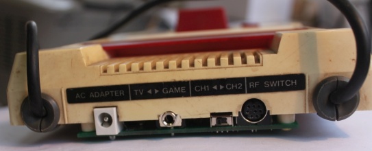
While on the subject of audio, here are some recordings from the Power/Audio board for the original Famicom. The CH1<>CH2 switch now selects between normal cartridge and Everdrive audio level for expansion audio.
aku-everdrive.mp3
aku-real-cartridge.mp3
There is a potentiometer on the board which can be used to adjust channel separation (fake stereo) from none to total. The following were recorded with moderate separation.
aku-everdrive-simulated-stereo.mp3
silius-simulated-stereo.mp3
aku-everdrive.mp3
aku-real-cartridge.mp3
There is a potentiometer on the board which can be used to adjust channel separation (fake stereo) from none to total. The following were recorded with moderate separation.
aku-everdrive-simulated-stereo.mp3
silius-simulated-stereo.mp3