I've been talking back and forth with Jason (Game - Tech) about proper audio separation (some of you may call it stereo) with the Twin Famicom and the NES RGB board.
Someone please correct me if I'm wrong, but I believe that the best way to do this is to just bypass the on board audio amp of the NESRGB and pull the sound channels directly from the system. I suppose the question is: Is it worth pulling the audio signals directly from the board before passing through the amp/filter audio circuit of the T.F.??
Or, is there a more effective way that's been documented? The Twin Famicom ' s audio circuit is pretty funky.
If this has been covered for the Twin Famicom previously in this thread, I do apologize, and would certainly appreciate the cite/reference.
NESRGB board available now
-
Voultar

- Posts: 550
- Joined: Fri Jan 10, 2014 8:29 pm
- Location: USA
-
viletim
- Posts: 565
- Joined: Mon Aug 07, 2006 6:44 am
- Location: Sydney, Australia
- Contact:
Re: NESRGB board available now
Send me an email and I'll organise one for you.lettuce wrote: Does anyone in the UK have one of these USB blasters than can lend me, so i can update my NESRGB??
It's best to ignore the audio circuit on the NESRGB in this case. The Twin's audio circuit is complicated because it accepts audio from the cartridge and the disk system for mixing.Voultar wrote:Someone please correct me if I'm wrong, but I believe that the best way to do this is to just bypass the on board audio amp of the NESRGB and pull the sound channels directly from the system. I suppose the question is: Is it worth pulling the audio signals directly from the board before passing through the amp/filter audio circuit of the T.F.??
-
lettuce

- Posts: 1336
- Joined: Wed Jun 22, 2011 7:10 pm
- Location: Bedfordshire, England.
Re: NESRGB board available now
viletim wrote:Send me an email and I'll organise one for you.lettuce wrote: Does anyone in the UK have one of these USB blasters than can lend me, so i can update my NESRGB??
Cheers, email sent
-
FriendofSonic
- Posts: 89
- Joined: Fri Mar 14, 2014 5:45 pm
Re: NESRGB board available now
Well, I preordered my board to be including in Jason's (Game-Tech) third batch of people. Let the hype begin
-
keropi

- Posts: 323
- Joined: Sat Sep 20, 2008 9:33 am
- Location: Ioannina , Greece
Re: NESRGB board available now
anyone here has any tips on using the NESRGB with the framemeister? I opened a topic here: http://shmups.system11.org/viewtopic.php?f=6&t=49677 , I can't find a good SYNC value to use ... some games look fine, but the settings don't work on others or work for half the game screens or something... 
the problem is only on RGB mode, composite/svhs encoded from NESRGB work perfect with the framemeister
the problem is only on RGB mode, composite/svhs encoded from NESRGB work perfect with the framemeister
-
sazyario
- Posts: 65
- Joined: Tue Jan 07, 2014 2:03 pm
Re: NESRGB board available now
I'm hoping that Tim gets more boards ready soon!
I'm going to get a small stock of Top Loaders ready for purchase. 4, maybe 5 depending on my personal funds.
They'll use Tim's MiniDIN+Aux setup and will come with his scart cable.
They'll be re-capped and have a replacement 1.5a 7805.
I'm doing this more for fun than for profit.
The units will be without any other accessories. Just the top loader + scart cable.
-
mrkotfw

- Posts: 170
- Joined: Sun Nov 26, 2006 3:15 am
- Location: California
Re: NESRGB board available now
What is the recommended tool for removing the PPU? Everyone on the first 10 pages were recommending the Hakko 808.
Which one is the recommended one?
http://www.amazon.com/Hakko-808-KIT-Con ... 722&sr=8-1
http://www.amazon.com/Hakko-808-KIT-Des ... 22&sr=8-10
It looks like the one with the vacuum pump is what I would need...
Which one is the recommended one?
http://www.amazon.com/Hakko-808-KIT-Con ... 722&sr=8-1
http://www.amazon.com/Hakko-808-KIT-Des ... 22&sr=8-10
It looks like the one with the vacuum pump is what I would need...
Yaul: An awesome open source SEGA Saturn software development kit
-
ApolloBoy

- Posts: 939
- Joined: Sat Jan 28, 2012 7:17 pm
Re: NESRGB board available now
All 808s have a vacuum pump, that's the main component of a desoldering gun.mrkotfw wrote:It looks like the one with the vacuum pump is what I would need...
-
mrkotfw
- Posts: 170
- Joined: Sun Nov 26, 2006 3:15 am
- Location: California
Re: NESRGB board available now
That's a good point. I guess I didn't think that thoroughly.ApolloBoy wrote:All 808s have a vacuum pump, that's the main component of a desoldering gun.mrkotfw wrote:It looks like the one with the vacuum pump is what I would need...
I'll be getting the one with the two extra nozzles. It's an expensive purchase, but worth it.
Yaul: An awesome open source SEGA Saturn software development kit
-
mvsfan
- Posts: 1209
- Joined: Sat Oct 06, 2012 12:24 am
Re: NESRGB board available now
sorry if this has already been covered, but i keep getting error code 44 when trying to program my second batch nesrgb board. I just finished installing it and its working good except for the background bug.
the usb blaster is being recognized by windows 7 and the quartus software.
the usb blaster is being recognized by windows 7 and the quartus software.
-
Voultar
- Posts: 550
- Joined: Fri Jan 10, 2014 8:29 pm
- Location: USA
Re: NESRGB board available now
Are you providing power (5v) to the NESRGB whilst programing?mvsfan wrote:sorry if this has already been covered, but i keep getting error code 44 when trying to program my second batch nesrgb board. I just finished installing it and its working good except for the background bug.
the usb blaster is being recognized by windows 7 and the quartus software.
I've had the afternoon off, so I've started on my Twin Famicom install.

I had to do a minor repair on the Twin Famicom adapter board. A via was missing on pin 10, hence the blue 30 AWG Kynar that you might have already spotted.
-
mvsfan
- Posts: 1209
- Joined: Sat Oct 06, 2012 12:24 am
Re: NESRGB board available now
thats good that you saw the missing via.
I thought that the nes would provide the power to the nesrgb if you switched it on with no game in it.
also i noticed that the diagram says to provide 3.3v power to the nesrgb
wich one is it? 3.3 or 5v?
its not a problem i can disconnect the nesrgb from the nes and use an external power source if i need to.
-
Voultar
- Posts: 550
- Joined: Fri Jan 10, 2014 8:29 pm
- Location: USA
Re: NESRGB board available now
I've not flashed an NESRGB board, but from what I've read a couple of pages back:
If you're providing power to the NESRGB, I haven't a clue. I'm sure someone can chime in.Either by applying 3.3V to the JTAG port power terminals or +5V to the power input solder pads (near J3).
-
ApolloBoy
- Posts: 939
- Joined: Sat Jan 28, 2012 7:17 pm
Re: NESRGB board available now
If you have the NESRGB installed and the NES/Fami powered on, you now have 3.3V going to the CPLD, since the NESRGB board has a level shifter that provides 3.3V for the CPLD. You definitely don't want to feed it 5V unless you want to fry the CPLD.
The USB Blaster that Tim provided me when I reflashed mine and Sparky's boards was modified with a small voltage regulator (USB carries 5V) to provide 3.3V through the wiring harness.
The USB Blaster that Tim provided me when I reflashed mine and Sparky's boards was modified with a small voltage regulator (USB carries 5V) to provide 3.3V through the wiring harness.
-
coffeyrt

- Posts: 32
- Joined: Thu Feb 06, 2014 9:52 pm
Re: NESRGB board available now
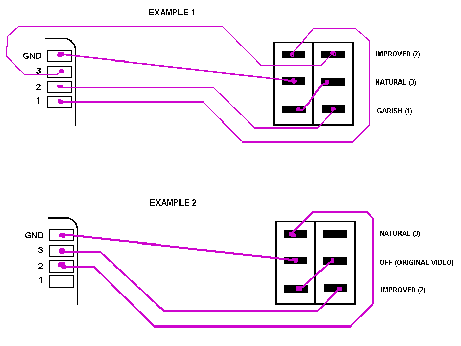
This is probably a very basic question but I am a bit new to electronics. I received Tim's board with the 3 way toggle. It seems that when turned to off, the circuit is just broken. If I want to retain all 4 options (improved, natural, garish, and off), can I just break the current between the board and the toggle switch through the ground, by adding a on/off button? Will this impair the function of the other options? Here is the diagram with the toggle switch. I want to do example one with an on/off button breaking the ground before it gets to the 3 way toggle. 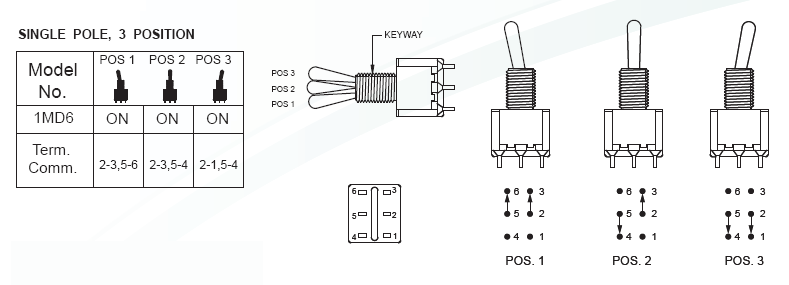
-
Voultar
- Posts: 550
- Joined: Fri Jan 10, 2014 8:29 pm
- Location: USA
Re: NESRGB board available now
Hardwired controllers be gone!!!!

^ I disassembled the Twin Fami controllers, and replace the controller cables with NES equivalents. The cables, as well as the original main-board connectors (which I've obviously replaced) have been placed in a zip-lock bag. I don't believe in butchering cables that are rather uncommon. It's quite nice being able to use a variety of NES controllers without touching the DB-15 port.
^ I disassembled the Twin Fami controllers, and replace the controller cables with NES equivalents. The cables, as well as the original main-board connectors (which I've obviously replaced) have been placed in a zip-lock bag. I don't believe in butchering cables that are rather uncommon. It's quite nice being able to use a variety of NES controllers without touching the DB-15 port.
-
mvsfan
- Posts: 1209
- Joined: Sat Oct 06, 2012 12:24 am
Re: NESRGB board available now
Providing that i have the nesrgb plugged in and the nes switched on - I only need 5 wires hooked up to the jtag connection correct?
Ive already checked to make sure i have the 4 programming wires in the right order. Is the diagram correct or is there some error on it?
Ive already checked to make sure i have the 4 programming wires in the right order. Is the diagram correct or is there some error on it?
-
SinNombre
- Posts: 3
- Joined: Tue Dec 10, 2013 5:48 am
Re: NESRGB board available now
coffeyrt wrote:This is probably a very basic question but I am a bit new to electronics. I received Tim's board with the 3 way toggle. It seems that when turned to off, the circuit is just broken. If I want to retain all 4 options (improved, natural, garish, and off), can I just break the current between the board and the toggle switch through the ground, by adding a on/off button? Will this impair the function of the other options? Here is the diagram with the toggle switch. I want to do example one with an on/off button breaking the ground before it gets to the 3 way toggle.
Hrm your picture says that is a single pole switch but it looks like a double pole switch to me with common terminals being 5 and 2. I don't see how you could choose from more than 2 of the settings without a conflict. I think maybe that's the wrong picture?
-
mvsfan
- Posts: 1209
- Joined: Sat Oct 06, 2012 12:24 am
Re: NESRGB board available now
hes using an on on on switch. thats not a double pole switch. look at the diagram again - see how theres actually 3 positions that the shunts move into?
going by this diagram,
your 3 palette positions should each be hooked up to pins 1, 3 and 6 and your ground should be hooked up to pin 5. there should be a jumper between pins 2 and 4.
going by this diagram,
your 3 palette positions should each be hooked up to pins 1, 3 and 6 and your ground should be hooked up to pin 5. there should be a jumper between pins 2 and 4.
-
coffeyrt
- Posts: 32
- Joined: Thu Feb 06, 2014 9:52 pm
Re: NESRGB board available now
Yes. This came from tim's website. http://etim.net.au/nesrgb/switch/ . I am wondering though if a simple on/off switch or button is wired between the ground and the board, if I would be able to 1. Turn the pallete on/off, then if it is on, it would then switch between the three pallets, therefore retaining all four option in a logical way. Here is a picture of what I am thinkingmvsfan wrote:hes using an on on on switch. thats not a double pole switch. look at the diagram again - see how theres actually 3 positions that the shunts move into?
going by this diagram,
your 3 palette positions should each be hooked up to pins 1, 3 and 6 and your ground should be hooked up to pin 5. there should be a jumper between pins 2 and 4.

-
Voultar
- Posts: 550
- Joined: Fri Jan 10, 2014 8:29 pm
- Location: USA
Re: NESRGB board available now
Tim certainly chose an interesting switch.
It wires up nicely, though.

I'm quite happy with the Twin Famicom install. Fortunately, the Twin Fami affords plenty of room underneath the mainboard, which makes wire management and neatness a breeze.
I decided to just move forward with just a standard multi-out, consolidating all A/V outputs to a single connector. It came out quite nicely. They typically will, if you do it correctly.

It wires up nicely, though.
I'm quite happy with the Twin Famicom install. Fortunately, the Twin Fami affords plenty of room underneath the mainboard, which makes wire management and neatness a breeze.
I decided to just move forward with just a standard multi-out, consolidating all A/V outputs to a single connector. It came out quite nicely. They typically will, if you do it correctly.


-
kazuo

- Posts: 42
- Joined: Tue Jul 29, 2008 7:03 am
- Location: Transylvania
Re: NESRGB board available now
Cristoph has said it is re-engineered and not based on existing hardware:Pasky wrote:BuckoA51 wrote:So have Analogue Interactive licensed this board from you Tim? http://www.analogueinteractive.com/inde ... nalogue-nt
It's just a Super 8 PCB + NESRGB in an aluminum case. Nothing special.
This seems to imply it incorporates neither a Super 8 or a NESRGB. There's a slight chance it may use Tim's board for video, but we'll find out at the end of the month, I guess.No FGPA or original motherboards. It's completely reengineered from the ground up. I'll have all the details at the end of the month. For the meantime, just know its not emulation.
-
keropi
- Posts: 323
- Joined: Sat Sep 20, 2008 9:33 am
- Location: Ioannina , Greece
Re: NESRGB board available now
regarding the palette switches, I wanted something less intrusive until I decide what I will finally use (switch or switchless PIC) so I just added a 3-position dip switch block on the grills at the backside of the famicom AV... 0 holes and if you bend the legs of the switch is stays into place 

works fine and is easily removed
works fine and is easily removed
-
leonk
- Posts: 1098
- Joined: Sun Mar 13, 2011 9:29 pm
- Location: Toronto, Canada
Re: NESRGB board available now
I think it would very difficult to switch the palette between games using this approach. I think it's more suitable for a set and forget type of usage.keropi wrote:regarding the palette switches, I wanted something less intrusive until I decide what I will finally use (switch or switchless PIC) so I just added a 3-position dip switch block on the grills at the backside of the famicom AV... 0 holes and if you bend the legs of the switch is stays into place
works fine and is easily removed
-
mvsfan
- Posts: 1209
- Joined: Sat Oct 06, 2012 12:24 am
Re: NESRGB board available now
Im going to try something else for the programming. im thinking that for some reason the nesrgb isnt getting enough power - because i keep getting error 44. Im going to take a 5v to 3.3v regulator out of my parts drawer and power the nesrgb off of the usb on the usb blaster.
or mabeye im doing something wrong i just dont know at this point. At least we shouldnt have to do this when the 3rd batch boards are sold.
heres a pic of the toploader im working on. I havent hooked any wires up yet i just wired in a composite jack so i could test it out. i didnt have time yesterday to finish the multi out.
those fat wires are just what i had laying around. I have some multi-colored ribbon cable im going to use for the multi-out.
I figured id program it before i hook up the multi-out.
everything seems to be working good sofar.
I also did a complete re-cap on this system and replaced the original voltage regulator with a 1.5a one.
it should last a long time with the recap and regulator.
Last edited by mvsfan on Mon Mar 24, 2014 4:15 pm, edited 1 time in total.
-
Vigormortis

- Posts: 61
- Joined: Sun Jan 19, 2014 7:07 am
Re: NESRGB board available now
Are you making sure to connect the voltage pin? (pin 1 on the NESRGB's JTAG connector and pin 4 on the USB blaster's connector). That has to be connected whether or not the USB blaster is supplying power.
-
mvsfan
- Posts: 1209
- Joined: Sat Oct 06, 2012 12:24 am
Re: NESRGB board available now
Vigormortis wrote:Are you making sure to connect the voltage pin? (pin 1 on the NESRGB's JTAG connector and pin 4 on the USB blaster's connector). That has to be connected whether or not the USB blaster is supplying power.
I dont understand. so if the usb blaster isnt modified then you still have to connect pin 4 on the usb blaster to pin 1?
so - if i was powering it externally id have to connect the 3.3v into pin 4 and then connect it to pin 1?
Let me try hooking it up and powering on the nes and see if that does the trick.
Last edited by mvsfan on Mon Mar 24, 2014 4:21 pm, edited 1 time in total.
-
Vigormortis
- Posts: 61
- Joined: Sun Jan 19, 2014 7:07 am
Re: NESRGB board available now
The normal purpose of USB blaster's pin 4 is to detect the voltage on the device being programmed, not to supply power.
edit: All you have to do is turn on your NES and program the NESRGB with all 6 wires hooked up to the JTAG port. An onboard voltage regulator on the NESRGB supplies the Altera chip with 3.3v, and pin 1 on its JTAG connector tells the USB blaster that it is being supplied with 3.3v.
edit: All you have to do is turn on your NES and program the NESRGB with all 6 wires hooked up to the JTAG port. An onboard voltage regulator on the NESRGB supplies the Altera chip with 3.3v, and pin 1 on its JTAG connector tells the USB blaster that it is being supplied with 3.3v.
Last edited by Vigormortis on Mon Mar 24, 2014 4:22 pm, edited 1 time in total.
-
mvsfan
- Posts: 1209
- Joined: Sat Oct 06, 2012 12:24 am
Re: NESRGB board available now
[quote="Vigormortis"]The normal purpose of USB blaster's pin 4 is to detect the voltage on the device being programmed, not to supply power.[/quote
now i understand.
now i understand.