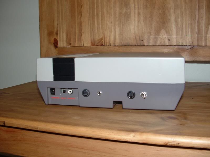
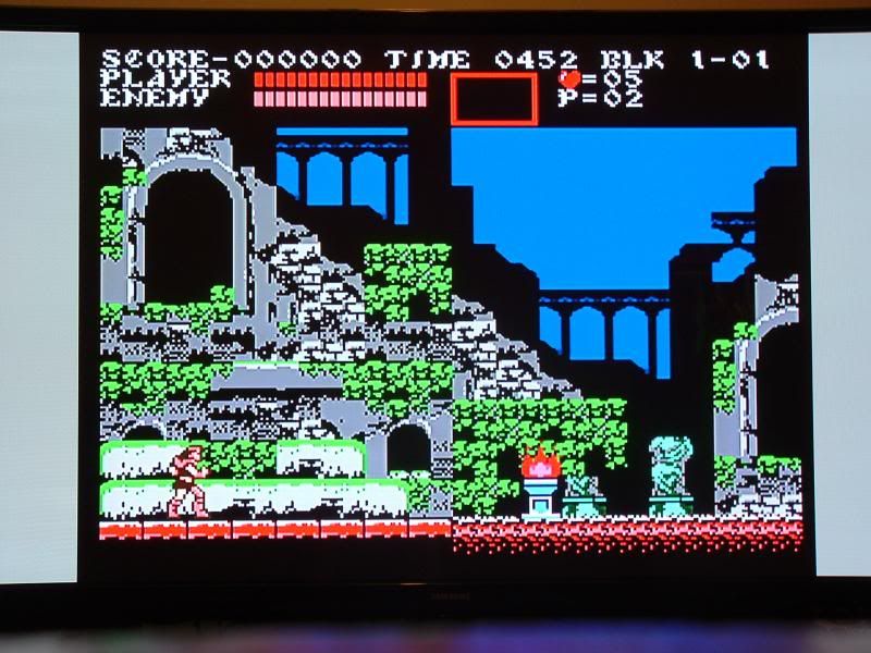
Here are some pics of the install and some screenshots. Note the voltage regulator heatsink modification I did. I am using a Samsung 51" PN51F4500 plasma and a CSY2100 (or equivalent) RGB SCART to component converter. The images look outstanding and my camera doesnt do them justice!
The csy 2100 DOES look nice. I also use one on a sony crt. some newer tvs may have issues with it though but a GBS-8220 rgb to vga board tends to fix them.
Also - has anyone done expansion sound on a nes toploader? I saw one vigormortis posted for the A/V famicom but where would it be connected on the toploader?
NESRGB board available now
-
ApolloBoy

- Posts: 939
- Joined: Sat Jan 28, 2012 7:17 pm
Re: NESRGB board available now
You would have to mod your Famicom converter for external audio (minus the resistor and cap that you would normally do when using it with a front loader), but instead of routing the audio to pin 54 on the NES side, you'd have to wire it to pin 51. Pin 54 is not physically present on the top loader so pin 51's your next best bet. From pin 51 you'd wire a 47k ohm resistor to the NESRGB's audio amp (just like with the Famicom), and there you have it.mvsfan wrote:Also - has anyone done expansion sound on a nes toploader? I saw one vigormortis posted for the A/V famicom but where would it be connected on the toploader?
If you're using a PowerPak or Everdrive, you'd need to add a jumper wire from pin 54 to pin 51, then do everything else after that.
My second NESRGB is on its way, and I plan on installing it in my top loader now that I have one of Helder's multiout panels. I'm going to be wiring it up for external audio so hopefully everything I said should work out.
-
Josh128

- Posts: 2363
- Joined: Thu Jan 16, 2014 9:01 am
Re: NESRGB board available now
[/quote]
Personally, I'm surprised it took you 4+ hours to just remove the PPU. I don't think I ever spend 2 mins [/quote]
BS. I'm done with that.
Personally, I'm surprised it took you 4+ hours to just remove the PPU. I don't think I ever spend 2 mins [/quote]
BS. I'm done with that.
-
Josh128
- Posts: 2363
- Joined: Thu Jan 16, 2014 9:01 am
Re: NESRGB board available now
leonk wrote:Personally, I'm surprised it took you 4+ hours to just remove the PPU. I don't think I ever spend 2 mins remove a PPU, yet alone spend 4 hours on the entire procedure beginning to end.Josh128 wrote:Considering the cheap, blunt (yet trusty) iron I was using and no extra flux, I'm quite satisfied with the results.
!
BS. I'm done with that. I challenge anyone to take a 27 year old NES with a 35W iron and a piston-type solder sucker and have the PPU out in 2 minutes. I want to see it.
First off, this is the first and only one Ive ever done. Second, I dont have the proper tools. Third, I dont give a damn about paying customers, I did this for myself. Fourth, this was done on my dining room table and I was interrupted by the wife and kids about 6,000 times.
My post was genuinely meant to help people who have problems with installing or are thinking about installing. I could care less how long it takes you or anyone else to desolder a chip. Knowing what I know now, using proper tools, yeah, pretty sure I could do it much more efficiently.
Last edited by Josh128 on Thu Mar 06, 2014 12:43 am, edited 2 times in total.
-
mufunyo
- Posts: 176
- Joined: Thu Jun 19, 2008 11:45 am
Re: NESRGB board available now
Y'all can be glad the PPU is so resilient to heat. I tried transplanting a ROM chip from a NES cartridge to an FC cartridge, and fried it within 5 minutes. I think 4 hours would've killed every single component involved.
-
markfrizb
- Posts: 83
- Joined: Fri Mar 25, 2011 2:32 pm
Re: NESRGB board available now
mufunyo wrote:Y'all can be glad the PPU is so resilient to heat. I tried transplanting a ROM chip from a NES cartridge to an FC cartridge, and fried it within 5 minutes. I think 4 hours would've killed every single component involved.
True that!!! Heat is a chip killer!
-
leonk
- Posts: 1098
- Joined: Sun Mar 13, 2011 9:29 pm
- Location: Toronto, Canada
Re: NESRGB board available now
When Kevin Horton was still making / selling CopyNES PCBs in the early 2000's (anyone remember these?) and I did not invest into proper tools (solder/desolder/reflow professional station that CAN remove the Nintendo CPU and PPU in less than 2 minutes with minimal amount of heat!) the best way (everyone cover their eyes!) I found to remove the CPU (and I'm sure this also applies to PPU) is using a heat gun.markfrizb wrote:True that!!! Heat is a chip killer!mufunyo wrote:Y'all can be glad the PPU is so resilient to heat. I tried transplanting a ROM chip from a NES cartridge to an FC cartridge, and fried it within 5 minutes. I think 4 hours would've killed every single component involved.
Yes... the CPU got hot. But it was for only 30 seconds or so. Yes, I'm ashamed of it now .. but it worked, and it got it out. And personally, I would rather shock the CPU/PPU with 30 seconds of heat rather than 4 hours! I know it's your NES, and I know you can do anything you damn want to do to it .. but my hope is this thread will showcase best practices rather than "hey .. if it worked for me, it should work for you!"
This is a hobby. And even after 12+ years of doing this, I still learn something new every day .. even from this thread. I hope the same is true for others. Learn from your work, learn from others, and share the experience. I was not trying to knock you down. I was just trying to provide you with positive criticism.
BTW.. we all have lives outside this hobby. I too have a wife and a 5 and 2 year old that keep me super busy ALL THE TIME.
-
Voultar

- Posts: 550
- Joined: Fri Jan 10, 2014 8:29 pm
- Location: USA
Re: NESRGB board available now
Josh128 wrote:leonk wrote:Josh128 wrote:
Knowing what I know now, using proper tool
It pays to have the proper tools.

I'll gladly accept your 2 minute PPU extraction challenge.
-
leonk
- Posts: 1098
- Joined: Sun Mar 13, 2011 9:29 pm
- Location: Toronto, Canada
Re: NESRGB board available now
nice ..
doing a cap kit on that CRT?
doing a cap kit on that CRT?
-
Voultar
- Posts: 550
- Joined: Fri Jan 10, 2014 8:29 pm
- Location: USA
Re: NESRGB board available now
leonk wrote:nice ..
doing a cap kit on that CRT?
I wish it would have been that simple.
The flyback transformer, horizontal output coil, horizontal output transistor, and horizontal deflection controller ALL went south at once. I'm rebuilding the entire deflection circuit, hopefully I'll be finished with it tomorrow. If I can spare the time.
-
Skips
- Posts: 404
- Joined: Tue Oct 22, 2013 3:03 am
Re: NESRGB board available now
If you are taking four hours with a piston type solder pump you need to do some more practicing. Exposing the PPU to heat that long is no bueno. I take about 7 to 10 minutes to remove a PPU with the piston hand pump and an iron, getting fast and efficient with it just takes practice.
I am no longer taking free or paid modding projects, please do not contact me asking for my services. Thanks .
-
opt2not

- Posts: 1289
- Joined: Fri May 20, 2011 6:31 pm
- Location: Southern California
Re: NESRGB board available now
Easy there tiger. There is no need to get defensive about it, leonk is just trying to give you some solid advice about your work. He's right, your soldering work could have been better, which is probably a result in not having the proper application of heat, or using the wrong type of solder. (actually, you mentioned you are an electrician? I wouldn't be surprised if you're using that high-grade electrical solder. That's how I screwed up my install.) But it's constructive criticism, which no one should get bent-out-of-shape over. It's meant to make you better at what you're doing, so that the next time you take on something like this, you won't be prone to errors. Leonk is a good guy, he helped me with my install after I botched it up, and his work is incredible. Proof: http://shmups.system11.org/viewtopic.ph ... 09#p991509Josh128 wrote:leonk wrote:Personally, I'm surprised it took you 4+ hours to just remove the PPU. I don't think I ever spend 2 mins remove a PPU, yet alone spend 4 hours on the entire procedure beginning to end.Josh128 wrote:Considering the cheap, blunt (yet trusty) iron I was using and no extra flux, I'm quite satisfied with the results.
!
BS. I'm done with that. I challenge anyone to take a 27 year old NES with a 35W iron and a piston-type solder sucker and have the PPU out in 2 minutes. I want to see it.
First off, this is the first and only one Ive ever done. Second, I dont have the proper tools. Third, I dont give a damn about paying customers, I did this for myself. Fourth, this was done on my dining room table and I was interrupted by the wife and kids about 6,000 times.
My post was genuinely meant to help people who have problems with installing or are thinking about installing. I could care less how long it takes you or anyone else to de-solder a chip. Knowing what I know now, using proper tool
I'm not as practiced as leonk -- he's been doing this kind of work for years ahead of both you and I, but I have done my fair share of solder work on arcade games for quite a few years now. Keeping neat and tidy solder-work isn't all about "looks", it's about longevity. Shoddy solder work will cause problems in the future, solder joints will deteriorate and cause collapse. I see this a lot when re-capping arcade monitors, or when working on older arcade PCB's.
I don't see the point in trying to show people the sub-par work you did as an example to those trying to decide to take this on. This doesn't help people. Your work, though functional, is not an example people should hold to. Standards should be higher than that! It's like people saying "you should wear a seat-belt when driving"...then you replying "Hey I drive fine, and haven't got into an accident so far". Because when it comes down to it, what's functional for you now, will probably not last the test of time. You want your 27 year old machine to last another 27 years, don't you?
Eat some humble pie, and heed the advice given to you by some of the more experienced guys.
Oh man, I really should invest in an 808.Voultar wrote:
It pays to have the proper tools.
I'll gladly accept your 2 minute PPU extraction challenge.
-
CkRtech

- Posts: 668
- Joined: Mon Aug 27, 2012 9:30 pm
- Location: Seattle, WA
Re: NESRGB board available now
Hey guys - I kinda abandoned my work on this one, and I blame indecision & tiredness from finding a simple, shielded, 8 pin mini din cable for an affordable price. I think I googled/ebayed around a bit and just never found one of decent length (6 feet) that is also good enough to carry video.
Various people have shown their work and mentioned some changes. I haven't decided exactly how I want to attack the case mod work yet, and I have a few other questions.
These questions apply to the front loader.
1: Did many of you use the 8 pin mini din connector? Are you using it with an 8P mini din cable or 8P to SCART cable?
2: Did you use the provided mini phono plug, replace it with a different mini phono plug, or go another route entirely?
3: Any panel-mounting struggles/recommendations with this apparently "thick-walled" NES? (I think that applies to the provided mini phono plug)
4: I have the extra voltage regulator hooked up to my system because I figured it couldn't hurt, yet I read somewhere about video issues when using it? Have any of you encountered this?
5: I have slide switch and also picked up an ON-ON-ON switch. Still undecided on which one to mount and where.
You can always unsolder, but you can't undrill.
-
Voultar
- Posts: 550
- Joined: Fri Jan 10, 2014 8:29 pm
- Location: USA
Re: NESRGB board available now
I'm using a Multi-Out on my front-loader. It's just easier to consolidate all of your outputs into one package.CkRtech wrote:Hey guys - I kinda abandoned my work on this one, and I blame indecision & tiredness from finding a simple, shielded, 8 pin mini din cable for an affordable price. I think I googled/ebayed around a bit and just never found one of decent length (6 feet) that is also good enough to carry video.
Various people have shown their work and mentioned some changes. I haven't decided exactly how I want to attack the case mod work yet, and I have a few other questions.
These questions apply to the front loader.
1: Did many of you use the 8 pin mini din connector? Are you using it with an 8P mini din cable or 8P to SCART cable?
2: Did you use the provided mini phono plug, replace it with a different mini phono plug, or go another route entirely?
3: Any panel-mounting struggles/recommendations with this apparently "thick-walled" NES? (I think that applies to the provided mini phono plug)
4: I have the extra voltage regulator hooked up to my system because I figured it couldn't hurt, yet I read somewhere about video issues when using it? Have any of you encountered this?
5: I have slide switch and also picked up an ON-ON-ON switch. Still undecided on which one to mount and where.
You can always unsolder, but you can't undrill.
My Twin Famicom will be using mini DIN connectors, and RCA outputs for audio & composite. Though I haven't entirely decided on how I'm going to attack that just yet.
-
eightbitminiboss
- Posts: 450
- Joined: Mon Sep 17, 2012 9:01 pm
Re: NESRGB board available now
Why use mini DIN on a Twin when you can just swap out the regular DIN (with minor modification to traces on the board) and avoid drilling a hole altogether?Voultar wrote:I'm using a Multi-Out on my front-loader. It's just easier to consolidate all of your outputs into one package.CkRtech wrote:Hey guys - I kinda abandoned my work on this one, and I blame indecision & tiredness from finding a simple, shielded, 8 pin mini din cable for an affordable price. I think I googled/ebayed around a bit and just never found one of decent length (6 feet) that is also good enough to carry video.
Various people have shown their work and mentioned some changes. I haven't decided exactly how I want to attack the case mod work yet, and I have a few other questions.
These questions apply to the front loader.
1: Did many of you use the 8 pin mini din connector? Are you using it with an 8P mini din cable or 8P to SCART cable?
2: Did you use the provided mini phono plug, replace it with a different mini phono plug, or go another route entirely?
3: Any panel-mounting struggles/recommendations with this apparently "thick-walled" NES? (I think that applies to the provided mini phono plug)
4: I have the extra voltage regulator hooked up to my system because I figured it couldn't hurt, yet I read somewhere about video issues when using it? Have any of you encountered this?
5: I have slide switch and also picked up an ON-ON-ON switch. Still undecided on which one to mount and where.
You can always unsolder, but you can't undrill.
My Twin Famicom will be using mini DIN connectors, and RCA outputs for audio & composite. Though I haven't entirely decided on how I'm going to attack that just yet.
-
Ed Oscuro

- Posts: 18654
- Joined: Thu Dec 08, 2005 4:13 pm
- Location: uoıʇɐɹnƃıɟuoɔ ɯǝʇsʎs
Re: NESRGB board available now
I can't recommend them enough myself. Did my first cap ever, a rather critical one to remove, in something like one minute flat (edit: Maybe two minutes - time flies when you're having fun!). No scorch marks on the PCB, no lifted traces. Probably took as long as it did because I didn't press the tip straight to the board right away (the 1mm tip was wider around that damn supercap lead than I was expecting, as it turned out), but tried to heat via the leg for a little while. But press it in to the solder blob carefully, press the trigger, done. I had to go back to the first leg and zap it again. Really clean desolder when it was done, though, hardly anything left on the board.opt2not wrote:Oh man, I really should invest in an 808.
Next thing for me to worry about is soldering - that I'm realizing I will need to turn some things upside down and rearrange to get a good workspace ready.
Last edited by Ed Oscuro on Wed Mar 05, 2014 7:56 pm, edited 1 time in total.
-
Voultar
- Posts: 550
- Joined: Fri Jan 10, 2014 8:29 pm
- Location: USA
Re: NESRGB board available now
Absolutely. In fact, you can severe the traces that lead up to the DIN in the Twin Famicom and wire directly into it. It's only use is for external RF modulation.eightbitminiboss wrote:Why use mini DIN on a Twin when you can just swap out the regular DIN (with minor modification to traces on the board) and avoid drilling a hole altogether?Voultar wrote:I'm using a Multi-Out on my front-loader. It's just easier to consolidate all of your outputs into one package.CkRtech wrote:Hey guys - I kinda abandoned my work on this one, and I blame indecision & tiredness from finding a simple, shielded, 8 pin mini din cable for an affordable price. I think I googled/ebayed around a bit and just never found one of decent length (6 feet) that is also good enough to carry video.
Various people have shown their work and mentioned some changes. I haven't decided exactly how I want to attack the case mod work yet, and I have a few other questions.
These questions apply to the front loader.
1: Did many of you use the 8 pin mini din connector? Are you using it with an 8P mini din cable or 8P to SCART cable?
2: Did you use the provided mini phono plug, replace it with a different mini phono plug, or go another route entirely?
3: Any panel-mounting struggles/recommendations with this apparently "thick-walled" NES? (I think that applies to the provided mini phono plug)
4: I have the extra voltage regulator hooked up to my system because I figured it couldn't hurt, yet I read somewhere about video issues when using it? Have any of you encountered this?
5: I have slide switch and also picked up an ON-ON-ON switch. Still undecided on which one to mount and where.
You can always unsolder, but you can't undrill.
My Twin Famicom will be using mini DIN connectors, and RCA outputs for audio & composite. Though I haven't entirely decided on how I'm going to attack that just yet.
It's an 8 POL connector, though. So you won't be able to tie everything into it. If you leave out encoded composite and have only mono audio, you can pull S-Video (Chroma & Luma), Audio RGB+Sync, and ground. Of course, there are a few variations here. It's all dependent on what you want to leave out.
I did consider using a Multi-Out on the Twin Famicom, but that would just be blasphemy.
^ I don't want to use that connector, primarily for the sake of abstaining from anything proprietary. Though, I haven't entirely decided. That's why my Twin Famicom is still sitting on my work-bench unmolested. I'm going to give that one a little more thought.
Last edited by Voultar on Wed Mar 05, 2014 7:56 pm, edited 3 times in total.
-
eightbitminiboss
- Posts: 450
- Joined: Mon Sep 17, 2012 9:01 pm
Re: NESRGB board available now
Well, that's what I meant. It's what I did with my Twin. I just have it hooked up for RGB with sync and audio. I have no use for composite. S-Video, I could potentially do since I left my sync connected to Luma, but not needed in my setup.Voultar wrote:
Absolutely. In fact, you can severe the traces that lead up to the DIN in the Twin Famicom and wire directly into it. It's only use is for external RF modulation.
It's an 8 POL connector, though. So you won't be able to tie everything into it. If you leave out encoded composite, you can pull S-Video (Chroma & Luma), Dual Audio, RGB, and ground.
-
Voultar
- Posts: 550
- Joined: Fri Jan 10, 2014 8:29 pm
- Location: USA
Re: NESRGB board available now
I like to say versatile as I can, without creating a cluster$#$# of a jambled mess.eightbitminiboss wrote:Well, that's what I meant. It's what I did with my Twin. I just have it hooked up for RGB with sync and audio. I have no use for composite. S-Video, I could potentially do since I left my sync connected to Luma, but not needed in my setup.Voultar wrote:
Absolutely. In fact, you can severe the traces that lead up to the DIN in the Twin Famicom and wire directly into it. It's only use is for external RF modulation.
It's an 8 POL connector, though. So you won't be able to tie everything into it. If you leave out encoded composite, you can pull S-Video (Chroma & Luma), Dual Audio, RGB, and ground.
I believe I'll tie RGB+ Sync into the existing connector, though. My "current" primary input source is S-Video.
-
TheRetromancer
- Posts: 116
- Joined: Fri Feb 07, 2014 9:27 pm
Re: NESRGB board available now
Damn straight! For years, I dealt with ache-y, sore fingers from squeezing those damned Radioshack desoldering iron bulbs, and finally threw my hands up in the air and let out an almighty curse at swapping those godawful iron tips that crumble after thirty minutes of use. I dropped about $200 on my 808, and I consider it money well spent. It made desoldering the PPU easy beyond measure - something that is a nightmare to consider with the Radioshack iron. Even when the collector gets jammed with solder, it's a two minute fix - whether the collector needs to be emptied, the pad changed, or the nozzle cleared - and I count it just as invaluable as my multimeter. Even moreso, in fact, than my soldering station!Ed Oscuro wrote:I can't recommend them enough myself. Did my first cap ever, a rather critical one to remove, in something like one minute flat (edit: Maybe two minutes - time flies when you're having fun!). No scorch marks on the PCB, no lifted traces. Probably took as long as it did because I didn't press the tip straight to the board right away (the 1mm tip was wider around that damn supercap lead than I was expecting, as it turned out), but tried to heat via the leg for a little while. But press it in to the solder blob carefully, press the trigger, done. I had to go back to the first leg and zap it again. Really clean desolder when it was done, though, hardly anything left on the board.opt2not wrote:Oh man, I really should invest in an 808.
Next thing for me to worry about is soldering - that I'm realizing I will need to turn some things upside down and rearrange to get a good workspace ready.
Invest - you will NEVER regret it!
"Thanks for the nice reply. I do offer to do work without hot glue too if people prefer it that way." - Drakon
-
leonk
- Posts: 1098
- Joined: Sun Mar 13, 2011 9:29 pm
- Location: Toronto, Canada
Re: NESRGB board available now
tip for those of you de-soldering any IC:
- if not enough suction pressure was used to clean out the hole, sometimes no amount of suction will clean it out a second time (even if you're using a desoldering station or the 808).
- to correct, using your soldering iron/station and reflow/add solder to the pin! Then desolder a second time.
Always does the trick for me.
-
opt2not
- Posts: 1289
- Joined: Fri May 20, 2011 6:31 pm
- Location: Southern California
Re: NESRGB board available now
Darn, the cheapest 808 I can find is about $179 on fleebay. Then there's the international shipping rapage they take a cut of. Amazon has it for $180, so I might go that route. Gonna have to wait till I finish my next paid art commission before I throw money at it, but I'm convinced, I'm getting one of these suckers (hehe pun intended) 

-
mvsfan
- Posts: 1209
- Joined: Sat Oct 06, 2012 12:24 am
Re: NESRGB board available now
i see some are worried about frying the ppu with heat. Ive never worried much about it and i havent fried anything either. If you turn the soldering iron way way up you might fry the ppu but an adjustable soldering station that regulates the iron temperature works wonders.
they dont cost a lot either.
Another thing to remember is that these components are designed to be heated up enough to solder them in place. otherwise they would be frying everything at the factory.
they dont cost a lot either.
Another thing to remember is that these components are designed to be heated up enough to solder them in place. otherwise they would be frying everything at the factory.
-
XianXi
- Posts: 40
- Joined: Thu Jan 22, 2009 7:36 am
- Location: Jamma Nation X
- Contact:
Re: NESRGB board available now
With an 808, you can remove the PPU within 30 seconds.Voultar wrote:I'll gladly accept your 2 minute PPU extraction challenge.
-
RGB32E

- Posts: 1400
- Joined: Thu Nov 05, 2009 12:50 am
Re: NESRGB board available now
BS! Prove it! Fresh solder joints not allowed. That's 1.3 pins fully cleared per second!?XianXi wrote:With an 808, you can remove the PPU within 30 seconds.Voultar wrote:I'll gladly accept your 2 minute PPU extraction challenge.
-
XianXi
- Posts: 40
- Joined: Thu Jan 22, 2009 7:36 am
- Location: Jamma Nation X
- Contact:
Re: NESRGB board available now
I can't prove it but I have done it with the above unit I modded. You do need to turn up the heat on the unit though(stock setting no way) and have a new filter and clean reservoir.RGB32E wrote:BS! Prove it! Fresh solder joints not allowed. That's 1.3 pins fully cleared per second!?XianXi wrote:With an 808, you can remove the PPU within 30 seconds.Voultar wrote:I'll gladly accept your 2 minute PPU extraction challenge.
-
Josh128
- Posts: 2363
- Joined: Thu Jan 16, 2014 9:01 am
Re: NESRGB board available now
Decided to install the palette switch and Svideo today. Set the ON-ON-ON switch to Natural, Off, Improved. Did this to preserve my original composite port should it ever be needed.
Few observations:
1. The palette switch works with S-video. Both look fantastic on my 36" SD CRT. Improved looks "nicer".
2. S-Video gives black screen if palette switch is in off position.
3. Composite out seems to look better than I remember, perhaps because it is now being produced by the NESRGB.
4. Composite out gives gray picture when palette switch is not in off position.
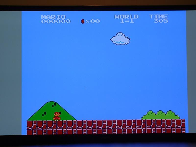
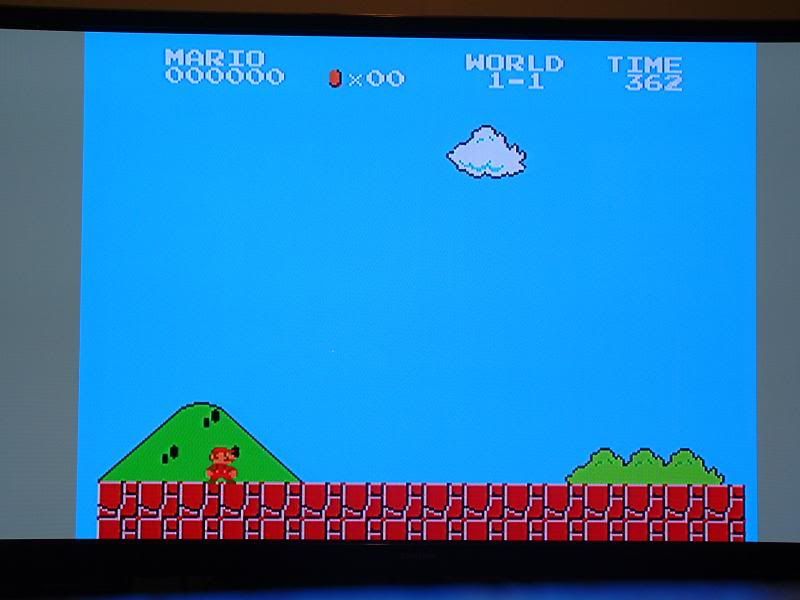
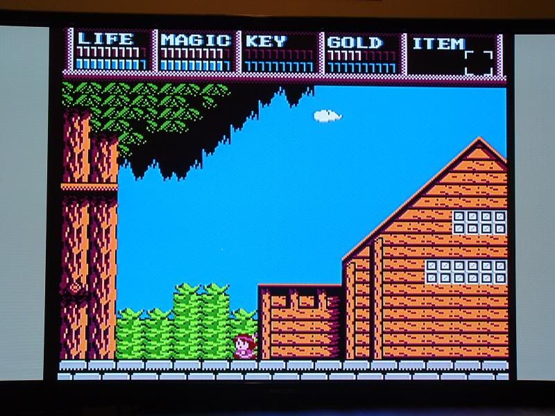
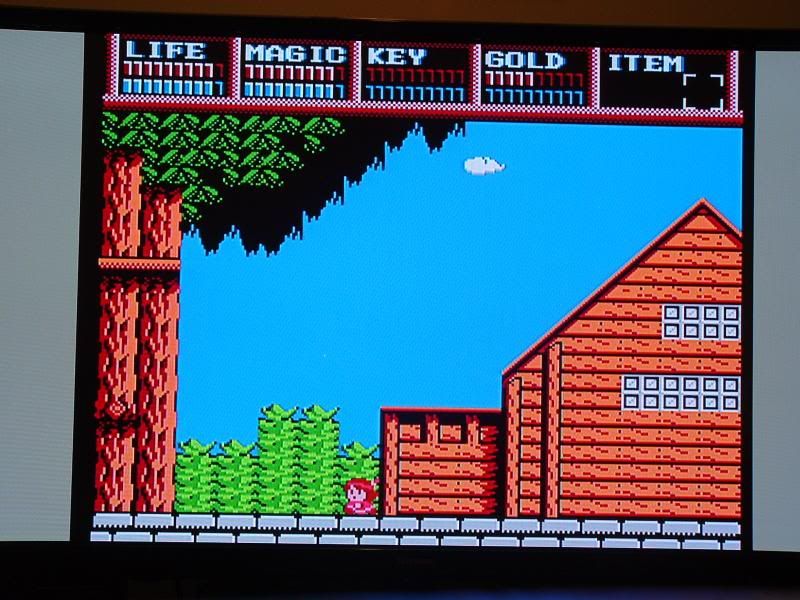
As far as the palettes go-- with my original install I jumped the "natural" position and while it looked good, clean, sharp with RGB, colors looked a bit drab. Now that I have the switch, I find "Improved" looks quite a bit better, more vibrant. I did notice that browns are a little reddish though on some games/objects. Overall, I prefer "Improved" and find it looks much more like what you would expect from RGB.
Below are some pics of the new mods on the back of my Nes and some palette comparison shots. I also show some composite and Svideo shots.
Following pics compare natural and improved on plasma RGB, natural shown first:
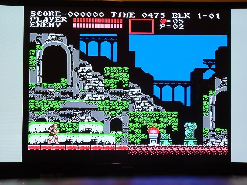
S-Video on 36" SD CRT below, natural shown first:
Few observations:
1. The palette switch works with S-video. Both look fantastic on my 36" SD CRT. Improved looks "nicer".
2. S-Video gives black screen if palette switch is in off position.
3. Composite out seems to look better than I remember, perhaps because it is now being produced by the NESRGB.
4. Composite out gives gray picture when palette switch is not in off position.
As far as the palettes go-- with my original install I jumped the "natural" position and while it looked good, clean, sharp with RGB, colors looked a bit drab. Now that I have the switch, I find "Improved" looks quite a bit better, more vibrant. I did notice that browns are a little reddish though on some games/objects. Overall, I prefer "Improved" and find it looks much more like what you would expect from RGB.
Below are some pics of the new mods on the back of my Nes and some palette comparison shots. I also show some composite and Svideo shots.

Following pics compare natural and improved on plasma RGB, natural shown first:


S-Video on 36" SD CRT below, natural shown first:


-
Ed Oscuro
- Posts: 18654
- Joined: Thu Dec 08, 2005 4:13 pm
- Location: uoıʇɐɹnƃıɟuoɔ ɯǝʇsʎs
Re: NESRGB board available now
It's worth it. I should have bought one of those the first time - mine was somewhat used, though advertised as used. I guess the $8 savings will get me another tip though, should I need it.opt2not wrote:Darn, the cheapest 808 I can find is about $179 on fleebay.
-
Vigormortis

- Posts: 61
- Joined: Sun Jan 19, 2014 7:07 am
Re: NESRGB board available now
Any improvement in the video quality from your NES's original composite video jack is imaginaryJosh128 wrote: 3. Composite out seems to look better than I remember, perhaps because it is now being produced by the NESRGB.
4. Composite out gives gray picture when palette switch is not in off position.
There is actually another composite output from the NESRGB in which there is definitely a difference. It's the solder pad labeled 'V'. That pad outputs composite video that has been encoded from the RGB image. It is affected by the palette switch in exactly the same way as the s-video and RGB outputs.
-
Josh128
- Posts: 2363
- Joined: Thu Jan 16, 2014 9:01 am
Re: NESRGB board available now
opt2not wrote: Easy there tiger. There is no need to get defensive about it, leonk is just trying to give you some solid advice about your work. He's right, your soldering work could have been better, which is probably a result in not having the proper application of heat, or using the wrong type of solder. (actually, you mentioned you are an electrician? I wouldn't be surprised if you're using that high-grade electrical solder. That's how I screwed up my install.) But it's constructive criticism, which no one should get bent-out-of-shape over. It's meant to make you better at what you're doing, so that the next time you take on something like this, you won't be prone to errors. Leonk is a good guy, he helped me with my install after I botched it up, and his work is incredible. Proof: http://shmups.system11.org/viewtopic.ph ... 09#p991509
I'm not as practiced as leonk -- he's been doing this kind of work for years ahead of both you and I, but I have done my fair share of solder work on arcade games for quite a few years now. Keeping neat and tidy solder-work isn't all about "looks", it's about longevity. Shoddy solder work will cause problems in the future, solder joints will deteriorate and cause collapse. I see this a lot when re-capping arcade monitors, or when working on older arcade PCB's.
I don't see the point in trying to show people the sub-par work you did as an example to those trying to decide to take this on. This doesn't help people. Your work, though functional, is not an example people should hold to. Standards should be higher than that! It's like people saying "you should wear a seat-belt when driving"...then you replying "Hey I drive fine, and haven't got into an accident so far". Because when it comes down to it, what's functional for you now, will probably not last the test of time. You want your 27 year old machine to last another 27 years, don't you?
Eat some humble pie, and heed the advice given to you by some of the more experienced guys.
I have no problem with constructive criticism, but essentially implying that Im incompetent because it took me 3 to 4 hours to remove the PPU, while bragging that he takes about 2 minutes is not constructive criticism, its a jab, and I took it as one. If your a professional, that is not a professional way to offer criticism. He completely ignored my writeup, voltage regulator mod, and zeroed in on the soldering and wiring. Jason from Gametech is a true professional and responded in a professional manner. I've been around long enough to know when someone is being facetious.
I have no doubt Leon does clean installs and is experienced in this. Im under no delusions that my work could have been much neater, cleaner, etc. Fact is, he passed judgment on me without knowing my situation, how much time I was willing to spend on the project, what tools I had on hand (I dont even have a pair of helping hands), etc., etc. All based on 2 fairly poor photos. My intention was not to show how great my soldering or wiring was, I simply posted them out of enthusiasm because I was happy with the results (it worked and the games looked great), and I wanted feedback on the voltage reg heatsink and the fact that I used the internal one, which Jason gave.
Leon said it looked like I had cold solder joints, I simply responded that I didnt. Do I think my work on the board is great/looks neat, no I dont. Am I confident in it? Yes I am. I was fine till the 4 hour/ 2 minute comment. I know how to solder and have been knowing how since 1999. Do I do it often? No. Have I ever had some work I did go bad because of a soldering job? Not that I can recall.
Its all good, Im willing to accept that his intentions were good and move on with it. All this aside, I'm way more interested in the functionality of the NESRGB kit and thats what I want to discuss.