So got my NESRGB finally working after having to reorder pin headers a couple of times. Finally found that these http://www.amazon.com/gp/product/B005HN ... UTF8&psc=1 can come in 2 days instead of waiting for China.
Couple of problems though. I noticed that the regular composite video is all black and white (mostly white). Did anyone else have this problem? Is this just improperly amped maybe?
Also has anyone tried Monster Party? It locks up at the beginning of the first level for me, but every other game in my collection works fine. I haven't tried it on an unmodded NES yet.
NESRGB board available now
-
LaC
- Posts: 38
- Joined: Fri Feb 01, 2013 12:35 am
- Location: Champaign, IL
-
mrkotfw

- Posts: 170
- Joined: Sun Nov 26, 2006 3:15 am
- Location: California
Re: NESRGB board available now
Welp, time for me to jump on the bandwagon.
I'm really excited for this!
I'm really excited for this!
Yaul: An awesome open source SEGA Saturn software development kit
-
ApolloBoy

- Posts: 939
- Joined: Sat Jan 28, 2012 7:17 pm
Re: NESRGB board available now
That's how it is if the NESRGB isn't shut off.LaC wrote:I noticed that the regular composite video is all black and white (mostly white). Did anyone else have this problem? Is this just improperly amped maybe?
-
mvsfan
- Posts: 1209
- Joined: Sat Oct 06, 2012 12:24 am
Re: NESRGB board available now
i dont understand why anyone would want to use the regular pass-through composite video when the nesrgb composite video is vastly superior.
I didnt hook up the pass-through, but i still have composite with almost no dot crawl.
I didnt hook up the pass-through, but i still have composite with almost no dot crawl.
-
mufunyo
- Posts: 176
- Joined: Thu Jun 19, 2008 11:45 am
Re: NESRGB board available now
I find that weird. Over the years I've always read the NES PPU touted as having the sharpest, cleanest composite of any console (comparing apples to apples). How would composite encoded from RGB look any better, assuming you're using the "natural" palette?mvsfan wrote:i dont understand why anyone would want to use the regular pass-through composite video when the nesrgb composite video is vastly superior.
-
leonk
- Posts: 1098
- Joined: Sun Mar 13, 2011 9:29 pm
- Location: Toronto, Canada
Re: NESRGB board available now
You're forgetting about the jail bars .. depending on your TV and console (front loader vs top loader) they're always there to some extent. Composite from NESRGB doesn't have them.mufunyo wrote:I find that weird. Over the years I've always read the NES PPU touted as having the sharpest, cleanest composite of any console (comparing apples to apples). How would composite encoded from RGB look any better, assuming you're using the "natural" palette?mvsfan wrote:i dont understand why anyone would want to use the regular pass-through composite video when the nesrgb composite video is vastly superior.
-
Fudoh

- Posts: 13047
- Joined: Mon Mar 06, 2006 3:29 am
- Location: Germany
- Contact:
Re: NESRGB board available now
leonk is right. If you want "good" composite, the NESRGB board is a nice solution. But all this aside: the NES' "stock" composite output really isn't any good. Compare it to a TG16/PCE's composite signal. That's a really good composite signal.
-
LaC
- Posts: 38
- Joined: Fri Feb 01, 2013 12:35 am
- Location: Champaign, IL
Re: NESRGB board available now
Ah you mean via the palette switch. I never hooked up the palette switch. I just have the pins shorted to lock the natural palette. I'll have to try that.ApolloBoy wrote:That's how it is if the NESRGB isn't shut off.LaC wrote:I noticed that the regular composite video is all black and white (mostly white). Did anyone else have this problem? Is this just improperly amped maybe?
Does the composite signal need to be amped like the NES composite signal does?
-
ApolloBoy
- Posts: 939
- Joined: Sat Jan 28, 2012 7:17 pm
Re: NESRGB board available now
No.LaC wrote:Does the composite signal need to be amped like the NES composite signal does?
-
alimadhi
- Posts: 30
- Joined: Sun Jan 26, 2014 12:53 pm
Re: NESRGB board available now
and about cart TV Hitachi i got this fuckn issuealimadhi wrote:i have problem with upper screen noise like 2 centimeter and every 5-10 sec the screen moving to the right like 1 centimeter quickly and come back like blink
My TV LED Samsung support scart [ext RGB] and i test megadrive, ps1 and old xbox no problem
I dont know what is my T.W board ver. i just received it with replacement chip.


Shownic LED TV S-Video mod

what the problem ? with Firmware or my board bad ? i test the board with 7 consoles 5 PAL and 2 NTSC
-
TheRetromancer
- Posts: 116
- Joined: Fri Feb 07, 2014 9:27 pm
Re: NESRGB board available now
1. If you mean that one of each pair of pins on the switch needs to go to GND, meaning three grounded pins, then no. Only a single pin is required to go to GND - you can find explicit instructions here: http://etim.net.au/nesrgb/switch/Josh128 wrote:Couple questions about the palette switching function and the ON-ON-ON toggle switch now included in the kits-
1. To switch to a certain palette, you must connect one of the palette pins to ground, right?
2. What happens if you switch the palette while a game is running? Does it update real time or must you reset the system? Can it damage anything to switch while running?
3. The ON-ON-ON switch Tim includes in the kit does not seem to be able to switch any single connection (GND) to 3 different ones to select all the palettes. Testing with ohm meter, it looks like at most you can use it to switch between 2 palettes with no "OFF" option. What am I not seeing here?
2. Switching the palette while a game is running does just that. There is a slight flicker, almost too fast to see, and the colours change. No interference, no dropped sprites, no rendering failures of any kind. It's actually rather brilliantly done.
3. The answer is found in my above posted link as well.
"Thanks for the nice reply. I do offer to do work without hot glue too if people prefer it that way." - Drakon
-
Josh128

- Posts: 2363
- Joined: Thu Jan 16, 2014 9:01 am
Re: NESRGB board available now
Thanks for the response. Yes, I know only one ground is needed, I just wasnt exactly clear that you were supposed to switch the inputs to ground to switch palette. The ON-ON-ON switch is a peculiar thing, but I saw on Tims page earlier today how it can be hooked up. I ended up just jumping GND and the "Natural" pin.TheRetromancer wrote:1. If you mean that one of each pair of pins on the switch needs to go to GND, meaning three grounded pins, then no. Only a single pin is required to go to GND - you can find explicit instructions here: http://etim.net.au/nesrgb/switch/Josh128 wrote:Couple questions about the palette switching function and the ON-ON-ON toggle switch now included in the kits-
1. To switch to a certain palette, you must connect one of the palette pins to ground, right?
2. What happens if you switch the palette while a game is running? Does it update real time or must you reset the system? Can it damage anything to switch while running?
3. The ON-ON-ON switch Tim includes in the kit does not seem to be able to switch any single connection (GND) to 3 different ones to select all the palettes. Testing with ohm meter, it looks like at most you can use it to switch between 2 palettes with no "OFF" option. What am I not seeing here?
2. Switching the palette while a game is running does just that. There is a slight flicker, almost too fast to see, and the colours change. No interference, no dropped sprites, no rendering failures of any kind. It's actually rather brilliantly done.
3. The answer is found in my above posted link as well.
Good news is I completed the install about an hour ago and the sucker actually works!! "Woohoo" was my first word-- there was so many things that could have went wrong that I wasnt really even expecting it to work, but it did first time I fired it up! Just before firing it up I check continuity/resistance at several points and found that my +5V regulator was shorted to ground-- thank God I found it and cleaned up some solder joints and cleared it before I plugged it in!
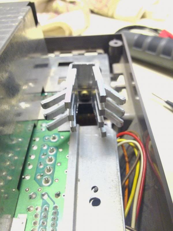
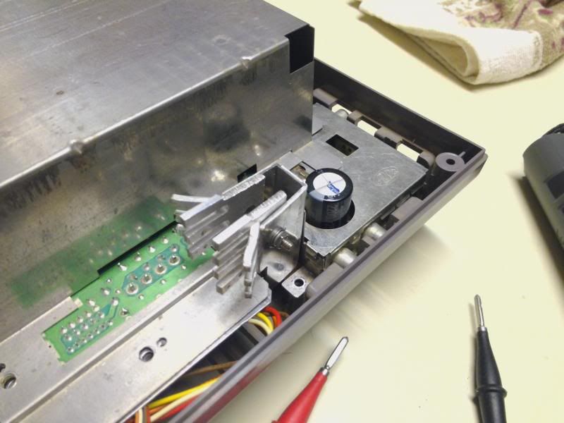
I also ended up using the NES internal 5V regulator because I didnt get one from Tim. I have a frontloader and I read that the reg will get very hot, so I ended up cutting some heatsinks off an old Pentium 3 motherboard and resizing them and bolting them to the regulator sink after taking everything apart, cleaning, and adding some Arctic Silver thermal grease. Good thing I did because I felt the sink after playing for 5 minutes or so and it was warm to the touch. I bet it really cooks if you dont add extra metal and thermal grease to the sink and regulator.
Also, even though Im NTSC, I didnt short the NTSC luma jumper and the output still looks fine?? Maybe it just affects the SVideo if you use it? Can someone elaborate? Does it affect color output with RGB and maybe Im just not noticing? Also, even though I used the NES +5 Regulator, I didnt short the solder jumper on the NESRGB board, I ran a set of wires directly to the regulator. I did this so that I can remove the wires and install the NESRGB regulator proper if Tim ever sends me one / or I decide that I simply must have one (if the NES one craps out or the heatsinks just arent enough, etc.). It looks like once you short one of those solder jumpers, theres no going back.
I really would like to hook up the SVideo and the palette switch, but I may wait a while because everything seems so delicate I dont want to take a chance of breaking something taking it back apart.
Ill post pics of the install and my frankenstein heatsink, screenshots, and more thoughts later.
-
game-tech.us

- Posts: 173
- Joined: Fri Aug 23, 2013 12:24 am
Re: NESRGB board available now
It has been proven the external regulator is very noisy and just not needed.Josh128 wrote: I really would like to hook up the SVideo and the palette switch, but I may wait a while because everything seems so delicate I dont want to take a chance of breaking something taking it back apart.
The stock heat sink is fine and prolly even the 1Amp 7805 will be fine, but I always upgrade to a new 1.5Amp version.
I posted a vid where I put a thermal camera on the stock sink, and it only ever got warm, not scolding hot.
Yes J5 is only for the svid and composite encoder.
-
Josh128
- Posts: 2363
- Joined: Thu Jan 16, 2014 9:01 am
Re: NESRGB board available now
So for your customers, you dont mod the sink, you just change out the the 7805 to the 1.5 amp version?game-tech.us wrote:It has been proven the external regulator is very noisy and just not needed.Josh128 wrote: I really would like to hook up the SVideo and the palette switch, but I may wait a while because everything seems so delicate I dont want to take a chance of breaking something taking it back apart.
The stock heat sink is fine and prolly even the 1Amp 7805 will be fine, but I always upgrade to a new 1.5Amp version.
I posted a vid where I put a thermal camera on the stock sink, and it only ever got warm, not scolding hot.
Yes J5 is only for the svid and composite encoder.
Also, it seems the RGB connector supplied with the kit and the cable itself dont seat very far into each other-- I played around with it trying to plug it deeper before realizing it actually worked like that. Is that normal?
Last edited by Josh128 on Tue Mar 04, 2014 8:00 pm, edited 1 time in total.
-
lettuce

- Posts: 1336
- Joined: Wed Jun 22, 2011 7:10 pm
- Location: Bedfordshire, England.
Re: NESRGB board available now
game-tech.us wrote:It has been proven the external regulator is very noisy and just not needed.Josh128 wrote: I really would like to hook up the SVideo and the palette switch, but I may wait a while because everything seems so delicate I dont want to take a chance of breaking something taking it back apart.
The stock heat sink is fine and prolly even the 1Amp 7805 will be fine, but I always upgrade to a new 1.5Amp version.
I posted a vid where I put a thermal camera on the stock sink, and it only ever got warm, not scolding hot.
Yes J5 is only for the svid and composite encoder.
Wait, so its recommended not to use the regulator supplied with the NESRGB and just use the one already in the NES??
-
keropi

- Posts: 323
- Joined: Sat Sep 20, 2008 9:33 am
- Location: Ioannina , Greece
Re: NESRGB board available now
@alimadhi
sadly it seems that there are lcd screens that have various errors... my LG ones have issues too.
Did you try on a crt? try it there to ensure this is not some installation issue.
sadly it seems that there are lcd screens that have various errors... my LG ones have issues too.
Did you try on a crt? try it there to ensure this is not some installation issue.
-
alimadhi
- Posts: 30
- Joined: Sun Jan 26, 2014 12:53 pm
Re: NESRGB board available now
@keropialimadhi wrote:and about cart TV Hitachi i got this fuckn issuealimadhi wrote:i have problem with upper screen noise like 2 centimeter and every 5-10 sec the screen moving to the right like 1 centimeter quickly and come back like blink
My TV LED Samsung support scart [ext RGB] and i test megadrive, ps1 and old xbox no problem
I dont know what is my T.W board ver. i just received it with replacement chip.
Shownic LED TV S-Video mod
what the problem ? with Firmware or my board bad ? i test the board with 7 consoles 5 PAL and 2 NTSC
I solved the problem i replaced the CPU & PPU with UMC UA6527P&UA6583 and the console works fine
Many Thanks
-
alimadhi
- Posts: 30
- Joined: Sun Jan 26, 2014 12:53 pm
Re: NESRGB board available now
alimadhi wrote:my NESRGB arrived today with replacement chip i replaced the chip and complete the mod but i got problem, the console work fine but after 1~2 mint the picture going to glich like this blow picture
here is my wiring


you guys remember this issue i solved it, I replaced the SN74LS373N chip with MM74HC373N and the console now works fine
Many Thanks
-
mvsfan
- Posts: 1209
- Joined: Sat Oct 06, 2012 12:24 am
Re: NESRGB board available now
I got my multi-out panel from Helder yesterday. I guess its time to build my toploader. Will post some pics whenever its done.
-
Josh128
- Posts: 2363
- Joined: Thu Jan 16, 2014 9:01 am
Re: NESRGB board available now
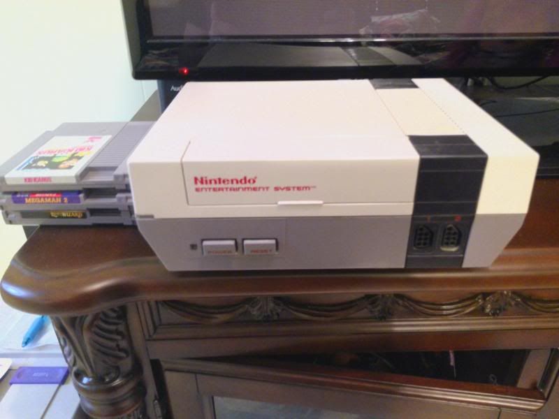
So yesterday I successfully finished the NESRGB installation in my childhood NES. Been having this system about 27 years and have logged countless hours on it, so yeah, the experience for me was akin to performing open heart surgery on a close friend. Thankfully he made it through fine and woke up when it was all over  !! I would have been a bit heartbroken had I bricked the system.
That said, couple thoughts on the installation-- first, everyone was right, desoldering the PPU is no joke. I used some cheap (I assume Chinese made sold in the US) solder wick, a 35W Jensen soldering iron with standard tip, and a Weller solder sucker. Following Tims advice to wick the solder from the topside of the chip as much as possible, then heating up joints and using the solder sucker. Im not exactly sure, but I probably logged around 4 hours just desoldering this thing. I found the most difficult pins were the ones soldered on the copper plane, and the ones closest to the expansion port. I found it difficult to wick solder from the ones close to the expansion port because there is very little room to get a soldering iron and wick between the expansion port and legs of the chip.
A tip I would like to share for removing the solder from the legs on the copper plane, and the only way I could do it: Support the board on its side in front of you, then use the iron with your left hand on the PPU side to heat up a leg. It takes a while, and to do it I found you need to press the iron firmly to the leg of the chip for about 20 or more seconds-- while doing this, use you use the solder sucker with your right hand to repeatedly suck while applying the heat on the other side-- with this technique you can extract all the solder from each of the 3 problem pins one at a time. For those concerned with holding the iron on the chip for so long, dont be-- the reason you have to is because the copper plane pulls heat away from the joint, so you have to stay on long enough to warm it all up. While doing this, I stopped every now and then and felt the chip top to see how hot it was getting, and while it does get warm, it doesnt really get any warmer than it does using the regular heat/suck technique used at the bottom for the other pins. This technique will save you a lot of headache if you dont have a proper desoldering iron.
Once most of the solder was sucked from the legs, I used an LED flashlight shining on the topside of the board while I looked from the bottom to see which holes I could see good light from. Even after seeing light from ALL the holes the chip was still firmly in place-- had to use some mini-needlenose pliers to wiggle the tips of each leg till the remaining traces of solder broke loose. Only after EVERY SINGLE leg moved freely was I able to grab the chip with my fingers and pull and wiggle, and it eventually came out.
One thing I found confusing was the solder jumpers. While I was relegated to having to use the on board voltage regulator for lack of the one provided, instead of jumping the solder jumper J3, I decided to run wires directly from the regulator to the +5V and GND on the NESRGB. I did this because I wanted the option to use an external regulator later should I need it. I dont know if anyone has had success doing it, but reversing these little solder jumpers does NOT look like it would be an easy task, or possible at all. Has anyone yet tried to do that?
Another thing which Tims write up doesnt describe very well (or in depth) is the fact that you must solder CPU pins one and two to the audio input on the NESRGB. I think its only mentioned on the drawing, and the drawing doesnt even show how to tell which pins on the CPU are actually 1 and 2. I googled how to find the pins and saw how some people had soldered to the resistors that were connected to them via board trace, so that is what I did.
Can anyone say how the NESRGB board audio is any better than the standard NES RCA audio? Once employed, does the NESRGB audio override the standard RCA audio / does the original even still work (havent tried it).
I have yet to install and hook up the palette switch (have natural jumped), and I have yet to jump install the SVideo plug and jump J5 Luma trap frequency for NTSC. I do want this functionality though, especially the palette switch ( I want to see how the "Improved" looks, if its more arcade like I may end up using it more often than not).
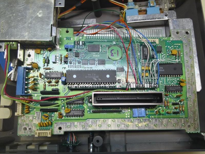
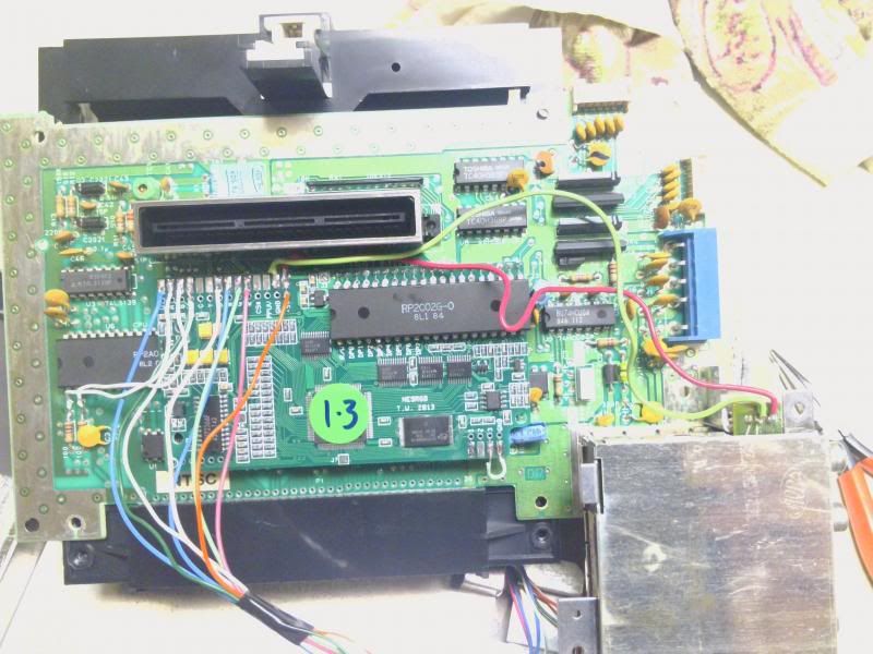
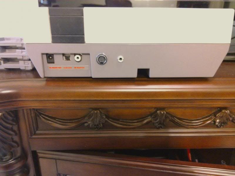
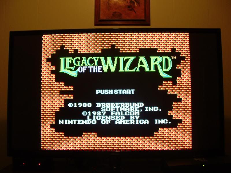
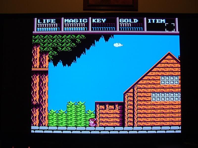
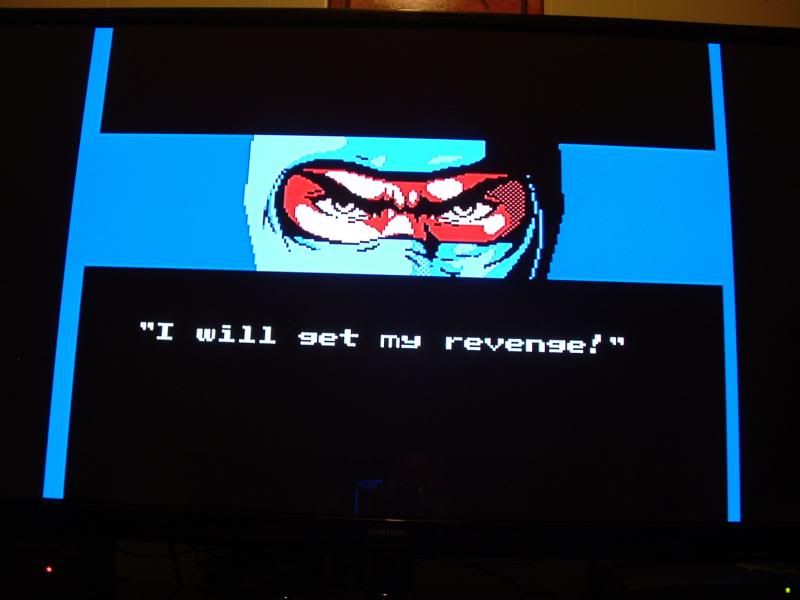
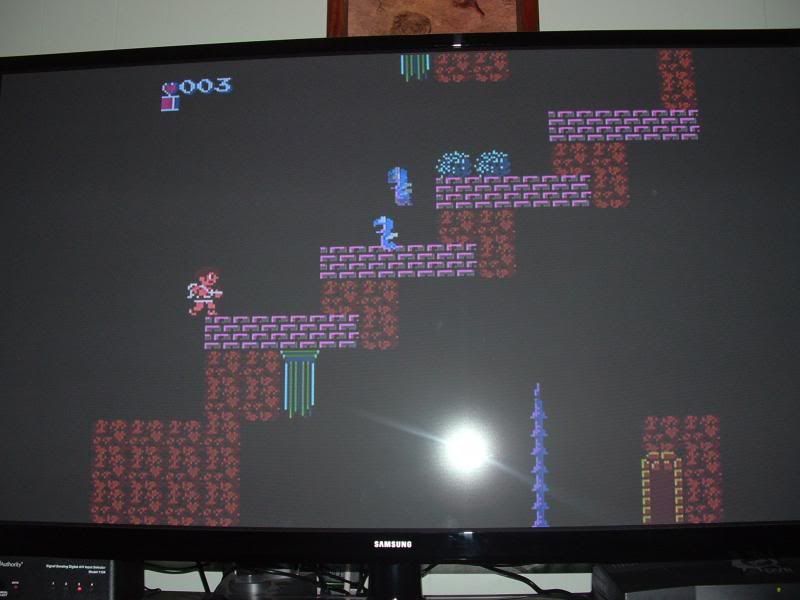
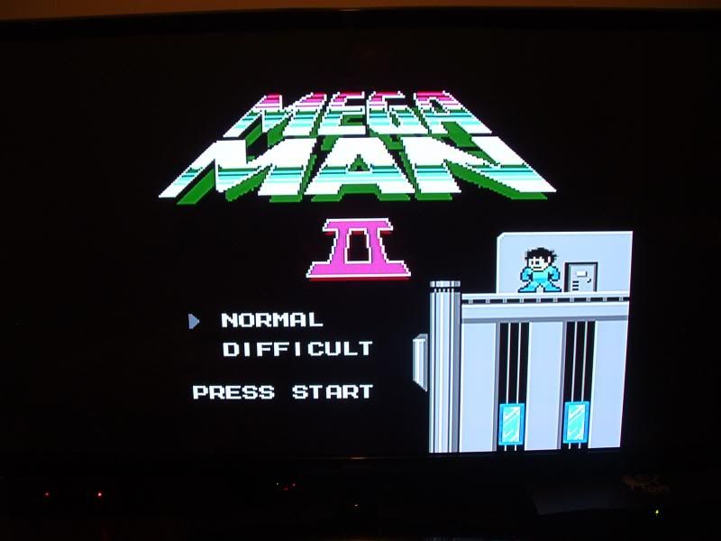
Here are some pics of the install and some screenshots. Note the voltage regulator heatsink modification I did. I am using a Samsung 51" PN51F4500 plasma and a CSY2100 (or equivalent) RGB SCART to component converter. The images look outstanding and my camera doesnt do them justice!
That said, couple thoughts on the installation-- first, everyone was right, desoldering the PPU is no joke. I used some cheap (I assume Chinese made sold in the US) solder wick, a 35W Jensen soldering iron with standard tip, and a Weller solder sucker. Following Tims advice to wick the solder from the topside of the chip as much as possible, then heating up joints and using the solder sucker. Im not exactly sure, but I probably logged around 4 hours just desoldering this thing. I found the most difficult pins were the ones soldered on the copper plane, and the ones closest to the expansion port. I found it difficult to wick solder from the ones close to the expansion port because there is very little room to get a soldering iron and wick between the expansion port and legs of the chip.
A tip I would like to share for removing the solder from the legs on the copper plane, and the only way I could do it: Support the board on its side in front of you, then use the iron with your left hand on the PPU side to heat up a leg. It takes a while, and to do it I found you need to press the iron firmly to the leg of the chip for about 20 or more seconds-- while doing this, use you use the solder sucker with your right hand to repeatedly suck while applying the heat on the other side-- with this technique you can extract all the solder from each of the 3 problem pins one at a time. For those concerned with holding the iron on the chip for so long, dont be-- the reason you have to is because the copper plane pulls heat away from the joint, so you have to stay on long enough to warm it all up. While doing this, I stopped every now and then and felt the chip top to see how hot it was getting, and while it does get warm, it doesnt really get any warmer than it does using the regular heat/suck technique used at the bottom for the other pins. This technique will save you a lot of headache if you dont have a proper desoldering iron.
Once most of the solder was sucked from the legs, I used an LED flashlight shining on the topside of the board while I looked from the bottom to see which holes I could see good light from. Even after seeing light from ALL the holes the chip was still firmly in place-- had to use some mini-needlenose pliers to wiggle the tips of each leg till the remaining traces of solder broke loose. Only after EVERY SINGLE leg moved freely was I able to grab the chip with my fingers and pull and wiggle, and it eventually came out.
One thing I found confusing was the solder jumpers. While I was relegated to having to use the on board voltage regulator for lack of the one provided, instead of jumping the solder jumper J3, I decided to run wires directly from the regulator to the +5V and GND on the NESRGB. I did this because I wanted the option to use an external regulator later should I need it. I dont know if anyone has had success doing it, but reversing these little solder jumpers does NOT look like it would be an easy task, or possible at all. Has anyone yet tried to do that?
Another thing which Tims write up doesnt describe very well (or in depth) is the fact that you must solder CPU pins one and two to the audio input on the NESRGB. I think its only mentioned on the drawing, and the drawing doesnt even show how to tell which pins on the CPU are actually 1 and 2. I googled how to find the pins and saw how some people had soldered to the resistors that were connected to them via board trace, so that is what I did.
Can anyone say how the NESRGB board audio is any better than the standard NES RCA audio? Once employed, does the NESRGB audio override the standard RCA audio / does the original even still work (havent tried it).
I have yet to install and hook up the palette switch (have natural jumped), and I have yet to jump install the SVideo plug and jump J5 Luma trap frequency for NTSC. I do want this functionality though, especially the palette switch ( I want to see how the "Improved" looks, if its more arcade like I may end up using it more often than not).
Here are some pics of the install and some screenshots. Note the voltage regulator heatsink modification I did. I am using a Samsung 51" PN51F4500 plasma and a CSY2100 (or equivalent) RGB SCART to component converter. The images look outstanding and my camera doesnt do them justice!
Last edited by Josh128 on Tue Mar 04, 2014 10:36 pm, edited 1 time in total.
-
ApolloBoy
- Posts: 939
- Joined: Sat Jan 28, 2012 7:17 pm
Re: NESRGB board available now
Urgh, seeing those thick wires on NESRGB installs makes me cringe big time.
-
CkRtech

- Posts: 668
- Joined: Mon Aug 27, 2012 9:30 pm
- Location: Seattle, WA
Re: NESRGB board available now
Thicker the better! Friends don't let friends use tiny wires!
-
Josh128
- Posts: 2363
- Joined: Thu Jan 16, 2014 9:01 am
Re: NESRGB board available now
The wires are actually extremely thin -- I pulled them from VGA cable, they are about 28 AWG. The jacket looks large, but the wires themselves are stranded and very small. The power wires, on the other hand are thicker-- they are about 18 or 20 AWG. You dont want too small of wire for power, regardless of the draw, if you have room for it. Take it from an electrician.ApolloBoy wrote:Urgh, seeing those thick wires on NESRGB installs makes me cringe big time.
-
leonk
- Posts: 1098
- Joined: Sun Mar 13, 2011 9:29 pm
- Location: Toronto, Canada
Re: NESRGB board available now
My bigger concern is the soldering on the NESRGB. Looks like there's some cold solder balls there. I know that most people reading this don't spend countless hours per week soldering (looking down in shame) but it could have been a tad neater. Maybe too much solder used or not enough heat.
Glad it worked out for you.
Glad it worked out for you.
-
TheRetromancer
- Posts: 116
- Joined: Fri Feb 07, 2014 9:27 pm
Re: NESRGB board available now
Erp. Yeah, that's kind of fugly soldering there. Still, if it works...leonk wrote:My bigger concern is the soldering on the NESRGB. Looks like there's some cold solder balls there. I know that most people reading this don't spend countless hours per week soldering (looking down in shame) but it could have been a tad neater. Maybe too much solder used or not enough heat.
Glad it worked out for you.
"Thanks for the nice reply. I do offer to do work without hot glue too if people prefer it that way." - Drakon
-
game-tech.us
- Posts: 173
- Joined: Fri Aug 23, 2013 12:24 am
Re: NESRGB board available now
You'd be able to 'wick' it off just fine.Josh128 wrote: Has anyone yet tried to do that?
-
game-tech.us
- Posts: 173
- Joined: Fri Aug 23, 2013 12:24 am
Re: NESRGB board available now
Correct.Josh128 wrote: So for your customers, you dont mod the sink, you just change out the the 7805 to the 1.5 amp version?
-
game-tech.us
- Posts: 173
- Joined: Fri Aug 23, 2013 12:24 am
Re: NESRGB board available now
The one Tim supplied seemed to add a lot of noise to the video for ppl who used it, I never did though.lettuce wrote: Wait, so its recommended not to use the regulator supplied with the NESRGB and just use the one already in the NES??
No on the stock 7805, I instal a new 1.5Amp 7805 in place of the stock 1Amp 7805.
-
Josh128
- Posts: 2363
- Joined: Thu Jan 16, 2014 9:01 am
Re: NESRGB board available now
Absolutely no cold solder joints anywhere in this install, but yes, a bit too much in some places. I always find when soldering wires more is better, especially when not using any kind of glue to secure the wires. Use too little solder and not enough length of wire when soldering to flat surfaces and you will be sorry when the joint breaks and the wire pulls off.leonk wrote:My bigger concern is the soldering on the NESRGB. Looks like there's some cold solder balls there. I know that most people reading this don't spend countless hours per week soldering (looking down in shame) but it could have been a tad neater. Maybe too much solder used or not enough heat.
Glad it worked out for you.
That said, criticisms of the soldering are amusing, but ultimately unwarranted-- my work is more function over form dudes, I could give two shits how good it looks sitting in the NES under that RF shield. More importantly, I am quite certain that there are no cold joints and most if not all of those little wires will break before any solder joint does, and none of the solder from any joint is touching anything it shouldnt. That said, there is nothing really wrong with the visuals of the the job either for that matter, I could have spent a couple more hours tidying things up, but I spent quite enough already on the install. The glare from the light in the first pic makes it look worse than it does in person-- the second pic with no glare is more indicative of how it looks, and its really not bad. Considering the cheap, blunt (yet trusty) iron I was using and no extra flux, I'm quite satisfied with the results.
-
leonk
- Posts: 1098
- Joined: Sun Mar 13, 2011 9:29 pm
- Location: Toronto, Canada
Re: NESRGB board available now
One should never use any extra flux when doing this sort of work. Extra flux is required only for SMD rework. The solder you use should have sufficient flux in it. As for how much solder, too much is just as bad as not enough .. as with anything in life, moderation / knowing how much is key.Josh128 wrote:Considering the cheap, blunt (yet trusty) iron I was using and no extra flux, I'm quite satisfied with the results.
If it work for you, who am I to knock your work down. I was just trying to provide you with some positive criticism.
Personally, I'm surprised it took you 4+ hours to just remove the PPU. I don't think I ever spend 2 mins remove a PPU, yet alone spend 4 hours on the entire procedure beginning to end. I know if Jason spent that kind of time on any of his work, it wouldn't make financial sense for him or anyone else doing this work for real paying customers.
Enjoy your NES!