Component Video mod for curved screen Sony Trinitrons

The place for all discussion on gaming hardware
roboblaster
Posts: 10
Joined: Sat Nov 09, 2024 11:04 am

Re: Component Video mod for curved screen Sony Trinitrons

Post by roboblaster »

I recently picked up an XF34M31 set that uses BG3S chassis. This is a later model than BG3R that I normally look for, and on this one they have removed the component input. I think it might have been a cheaper model.
Anyway, I added RGB SCART, but now I also want to add back the component input to use with PS2.
From reading up in this thread I think it should be possible but I could use some help interpreting the service manual.

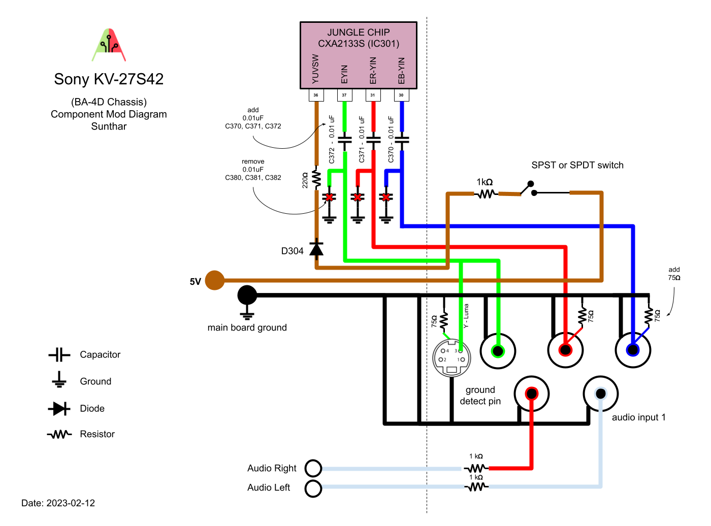
Tracing back the jungle inputs (36-39), it goes back to a header CN303. This looks like a good place to inject the signal.

My understanding is that I need coupling caps in the path and terminate the signals with 75 ohm to ground. Looking at the diagram there and highlighted pins:

https://imgur.com/qc5VQ31

RY: Coupling cap in circuit. Seems to be grounded via R312 (470 ohms? should R312 be removed?). It's also connected to Q302/Q303 matrix transistors (?? what's that about ??)
BY: Coupling cap in circuit. Not sure what diode to ground does, i assume it still needs termination with 75 ohm?
Y: Coupling cap in circuit, no grounding. The Y input will be split to go to jungle input and svideo luma so it shouldnt need termination?
YS: Havent figured out what voltage this needs to be yet, will have to check chip data sheet later

anyone able to help me decipher this to speed things up a bit? :)
Bard_the_Bowman
Posts: 37
Joined: Mon Apr 29, 2024 5:42 am

Re: Component Video mod for curved screen Sony Trinitrons

Post by Bard_the_Bowman »

matt wrote: Fri Jun 21, 2024 10:16 pm
Bard_the_Bowman wrote: Tue Jun 18, 2024 7:32 pmHey Matt, I tried going with this approach and I'm now getting a terrible interference/hum out of the right audio channel. Do you have any thoughts on what might be causing that or how I might reduce it?
Usually this is a grounding issue.
Turns out I was being really dumb. I have the horizontal switch shift wired into my 6P3T toggle, but at the time of that post I'd stuffed up the wiring. I had one of the wires for the horizontal shift switch going to a post that was supposed to be for one of the left audio wires, and vice versa. (used white wires for both and evidently got sloppy). So yeah, was probably sending voltage right into the audio circuit which unsurprisingly caused an unpleasant noise lol.

So, I guess the lesson is if you're doing this mod with a many-poled switch, just be VERY meticulous with your wiring.
MrSensible
Posts: 2
Joined: Tue May 27, 2025 11:58 pm

Re: Component Video mod for curved screen Sony Trinitrons

Post by MrSensible »

Having some trouble with very first CRT mod project. I am adding component video to my Sony 27S42 using Sunthar's guide (link: https://sector.sunthar.com/guides/crt-r ... 27s42.html). Unfortunately I am still having issues getting a proper image via the new component inputs.

For ease of reference, this is Sunthar's mod diagram for my CRT chassis:
Spoiler
Image
I have followed all of the written steps in the guide. I am also using an SPST switch to connect the 5V line to the YUVSW input on the main board. After completing the solder work, I connected a SNES via an HD Retrovision component cable. Currently, I do get an image when the SPST switch is set to the ON position, but it is very dark, almost like there is bad luma information coming through. However, when I throw the SPST switch back to the OFF position, I get a black and white (but appropriately bright) image:
Spoiler
Image
Image
A couple of points I am not clear on from the guide/diagram:
  • There are multiple ground lines shown running to the S-video connector. Currently I only have the top-middle pin connected to ground (via the green component jack's grounding tab). Are additional grounding wires necessary for any other pins on the S-video connector?
  • The written guide only mentions adding one 1000 ohm resistor to the 5V bodge wire on the board underside, and also to add 75 ohm termination resistors to both the Pb and Pr component jacks. However, Sunthar's diagram also shows a third 75 ohm resistor running to the S-video connector. Is that something I need to add as part of the mod, or is he just illustrating a component that's already part of the board?
Any suggestions on how to resolve the incorrect/missing luma signal when the 5V switch is set to ON? I have already replaced the ceramic capacitor at C372 since that's the one that bridges the luma signal from the S-video connector over to EYIN on the jungle chip, but this made no difference.
KPackratt2k
Posts: 266
Joined: Sun Apr 04, 2021 11:02 pm
Location: Seattle, WA, USA

Re: Component Video mod for curved screen Sony Trinitrons

Post by KPackratt2k »

You should not add a 75 ohm termination resistor to the Luma input, as S-Video Luma already has one. If you've added an additional termination resistor on your Luma jack, remove it.

Generally, you only need to run ground from only one place on the board. Your ground wire should run to the shields of all RCA jacks, you can use a solid core wire (in addition to the stranded wire that you're using to run the ground from the TV chassis to one jack) to extend the ground wire across all of your jacks.

On this set, there's an automatic S-Video detection circuit that can have issues with certain devices (mainly the Mister and the Sega Dreamcast). To improve compatibility with such devices, I recommend replacing your SPST switch with a DPDT switch, run the second pole to ground the detection pin for S-Video when Component video is active, and change the ID-1 setting to "17" in the service menu.

Make sure your Component Luma jack is wired to both the S-Video Luma input and the E-YIN pin of the header.
MrSensible
Posts: 2
Joined: Tue May 27, 2025 11:58 pm

Re: Component Video mod for curved screen Sony Trinitrons

Post by MrSensible »

KPackratt2k wrote: Wed May 28, 2025 1:48 am You should not add a 75 ohm termination resistor to the Luma input, as S-Video Luma already has one. If you've added an additional termination resistor on your Luma jack, remove it.

Generally, you only need to run ground from only one place on the board. Your ground wire should run to the shields of all RCA jacks, you can use a solid core wire (in addition to the stranded wire that you're using to run the ground from the TV chassis to one jack) to extend the ground wire across all of your jacks.

On this set, there's an automatic S-Video detection circuit that can have issues with certain devices (mainly the Mister and the Sega Dreamcast). To improve compatibility with such devices, I recommend replacing your SPST switch with a DPDT switch, run the second pole to ground the detection pin for S-Video when Component video is active, and change the ID-1 setting to "17" in the service menu.

Make sure your Component Luma jack is wired to both the S-Video Luma input and the E-YIN pin of the header.
Thanks for the troubleshooting advice. I only have the termination resistors on Pb and Pr, so I'm covered there.

As far as my ground wires, I ended up splicing three smaller segments of wire onto one end of my ground lead, and then connected those three segments to the ground shields on all three RCA jacks.

Later on, after testing the SNES and getting a rolling image, I realized that the S-video connector also needed to be grounded somehow in order to get sync via component input. I ended up connecting another wire to the Y/Green RCA shield, and ran that wire to the top-middle pin of the S-video connector to ground it. I am not 100% certain that this is the proper "detection pin" for the S-video connector (or that I used anything resembling proper grounding technique), but now I at least have an image that seems to be getting sync and does not roll. I may swap the SPST switch with a DPDT switch at some point, especially if I can figure out the brightness issue.

For reference, I have included some photos of my solder work. I am especially curious about the back of the S-video connector, and whether I have it wired correctly for Y/luma and grounding. I currently have the left-middle pin connected to the Green component jack's center pin, and then another wire from the jack runs to the EYIN header pin. Again, I grounded the S-video connector using the top-middle pin, with a wire running back to the green RCA shield.
Spoiler
Image
Image
Image
I also find it interesting that I ONLY get Y/luma signal when the SPST switch is thrown to the OFF position, but maybe this is normal behavior for this type of component mod?
KPackratt2k
Posts: 266
Joined: Sun Apr 04, 2021 11:02 pm
Location: Seattle, WA, USA

Re: Component Video mod for curved screen Sony Trinitrons

Post by KPackratt2k »

If you have access to a multimeter, you should do a continuity check to make sure the Luma line is properly connected to the E-YIN pin on the jungle chip and make sure the Luma inline capacitor (C372) isn't shorted either. It's also possible that the pad that connects the wire to the capacitor is broken. I once worked on a set that someone else tried to mod and found a broken trace on one of the Component input pads on the header, I had to use magnet wire to patch the connection on the board to make it work.
Post Reply