Oh well maybe Dreamcast scaling will be implemented by then
GBS 8200/8220 CFW Project
-
maxtherabbit

- Posts: 1763
- Joined: Mon Mar 05, 2018 4:03 pm
Re: GBS 8200/8220 CFW Project
Dope I ordered one. Probably be here in like 8 god damn weeks though
Oh well maybe Dreamcast scaling will be implemented by then
Oh well maybe Dreamcast scaling will be implemented by then
-
Higgy
- Posts: 54
- Joined: Thu Mar 15, 2018 1:29 pm
Re: GBS 8200/8220 CFW Project
Yep D1 Mini's work really well. With a PLCC socket and some matrix board you can make a very small plug on device. 
-
AndehX

- Posts: 790
- Joined: Sun Oct 18, 2015 11:37 pm
Re: GBS 8200/8220 CFW Project
Tried out the line blur filter thing and I must say, what a jump in clarity! It looks fantastic, as long as you don't use scanlines. Using scanlines can really highlight the fact it's not displaying at the monitors native res. The line blur can help hide it. I think if we ever get a 1080 profile, this will look absolutely fantastic.
-
maxtherabbit
- Posts: 1763
- Joined: Mon Mar 05, 2018 4:03 pm
Re: GBS 8200/8220 CFW Project
that's fantastic, I've got no use for artificial scanlines anywayAndehX wrote:Tried out the line blur filter thing and I must say, what a jump in clarity! It looks fantastic, as long as you don't use scanlines. Using scanlines can really highlight the fact it's not displaying at the monitors native res. The line blur can help hide it. I think if we ever get a 1080 profile, this will look absolutely fantastic.
-
rama
- Posts: 1373
- Joined: Wed Mar 08, 2017 3:15 pm
Re: GBS 8200/8220 CFW Project
Yeah, the line filter is a neat hardware feature
Higgy:
The URL for the ESP8266 definitions is still working fine here. The Github project description also still links to it.
Maybe a server issue yesterday? Don't see why it shouldn't work.
Higgy:
The URL for the ESP8266 definitions is still working fine here. The Github project description also still links to it.
Maybe a server issue yesterday? Don't see why it shouldn't work.
-
Higgy
- Posts: 54
- Joined: Thu Mar 15, 2018 1:29 pm
Re: GBS 8200/8220 CFW Project
I got ESP8266 working again on the IDE. From a web search other people have had this strange issue.
I also got gbscontrol2 working
Having a strange issue since there was WiFi changes with Firmware. Does not seem to show GBS UI and if have seen it I can't adjust anything (on my LG G4 phone) but using an old tablet I connect fine and could adjust?
I will try rebooting the phone.
I don't link the GBS to my home WiFi as I am not sure it picks up the router downstairs as when in have added home SSID and password I cannot connect (then in have to reprogram to clear the settings). So on my phone I disconnect from my home WiFi and connect directly to the ESP8266 WiFi.
-
rama
- Posts: 1373
- Joined: Wed Mar 08, 2017 3:15 pm
Re: GBS 8200/8220 CFW Project
It works in either mode.
The DNS lookup seems to be really slow initially. Once it sent the site, all following lookups are fast.
I'm no expert on this stuff, just following the examples and documentation that's available.
It seems like the ESP8266 doesn't cope well with mediocre WiFi conditions, but that is the best I can tell.
I'd advise you to wait longer for the site to show up. It will eventually.
-
Higgy
- Posts: 54
- Joined: Thu Mar 15, 2018 1:29 pm
Re: GBS 8200/8220 CFW Project
Strange. It works fine on phone's 'Chrome' browser. It just seems the internal browser is now broken? I can get the UI up but it does not do anything.
I will stick to Chrome from now on.
I will stick to Chrome from now on.
-
rama
- Posts: 1373
- Joined: Wed Mar 08, 2017 3:15 pm
Re: GBS 8200/8220 CFW Project
I use websockets for all interaction.
So allthough the page looks like the most basic HTML, it needs JavaScript and websocket support.
Websockets could be blocked in some configurations.
So allthough the page looks like the most basic HTML, it needs JavaScript and websocket support.
Websockets could be blocked in some configurations.
-
nmalinoski
- Posts: 1974
- Joined: Wed Jul 19, 2017 1:52 pm
Re: GBS 8200/8220 CFW Project
I'm just starting to look into getting one of these, as my OSSC isn't perfect, and my DSC 301 HD is not really what I was hoping for.
Is there a resource that describes the GBS 82xx boards with a concise list of features, supported video modes/formats, and example applications?
I skimmed the wiki on rama's GitHub page, but wasn't able to figure out things like: (in no particular order)
Is there a resource that describes the GBS 82xx boards with a concise list of features, supported video modes/formats, and example applications?
I skimmed the wiki on rama's GitHub page, but wasn't able to figure out things like: (in no particular order)
- What is the max scaling resolution? 1920x1080? 1920x1200? 1600x1200?
- Does it auto-detect changes between RGBS and RGsB, for seamless transitions between 480i and 480p+ on the PS2? (Gran Turismo 4 is a good use case; gameplay is in higher res, but always drops back to 480i for menus/videos)
- Can the DE-15 input also accept YPbPr, and is there auto-detection of that as well?
- Is anyone making cases for these?
- Is there an IR sensor for using something like an OSSC remote to navigate the on-screen menu system?
- How secure is the ESP8266 with the socket adapter?
- Do these boards have the capability of decoding CVBS and/or S-Video?
- At what point does the number of required/recommended/optional hardware modifications--replacing SMD caps, adding resistors/ferrite beads, removing pots--warrant building a custom PCB using the same components?
- Are the HDMI-output variants documented/supported? (And do they support YPbPr, or just RGB?
-
AndehX
- Posts: 790
- Joined: Sun Oct 18, 2015 11:37 pm
Re: GBS 8200/8220 CFW Project
The wiki you've read is pretty much the only resource at the moment as no one else has put much time or effort into this device.
I can't answer all of your question as Rama is the guru, not me, but I can answer a couple:
Max supported resolution right now is 1280x1024, but hopefully there will be some form of 1080p output in the future.
No idea about progressive transitions like 480p, but 240p -> 480i and vice versa is instant.
There are 3D print designs for this scaler on thingiverse.
At the moment, as far as I know, there is no IR sensor as the menu is accessed via web browser, not on screen.
The socket adapter isn't super secure. It will stay in place, but if you knock the scaler, for example, it can quite easily come loose. I secure mine with a drop of hot glue. Works a treat.
No S-video or CVBS support right now AFAIK.
The only hardware mods that are required are replacing the 2 sync SMD caps, and the 100ohm resistor on the sync line. There are other caps you can add to reduce interference, but they are not strictly necessary.
The HDMI variant is supported. It's the same scaler, it just has a built in HDMI encoder instead of a VGA output. I've literally just assembled one today, and it works fine.
It's not a perfect solution for everyone, not by far, but that's not the goal here. The main attraction of this device and this project as a whole, is the price. It's a ~$30 scaler that can come close to the OSSC and Framemeister quality with a bit of modding.
-
maxtherabbit
- Posts: 1763
- Joined: Mon Mar 05, 2018 4:03 pm
Re: GBS 8200/8220 CFW Project
IIRC the HDMI version just takes the analog output of the scaler IC's built in DAC and runs it into another ADC. A true digital to.digital version would be possible because the chip can output digital RGB, but such a thing does not exist
-
nmalinoski
- Posts: 1974
- Joined: Wed Jul 19, 2017 1:52 pm
Re: GBS 8200/8220 CFW Project
Is there someone we can get involved in this project who can design a new PCB around these chips that can take advantage of both the analogue and digital output from the DAC and has the ESP8266 baked in (or socketed)?maxtherabbit wrote:IIRC the HDMI version just takes the analog output of the scaler IC's built in DAC and runs it into another ADC. A true digital to.digital version would be possible because the chip can output digital RGB, but such a thing does not exist
-
rama
- Posts: 1373
- Joined: Wed Mar 08, 2017 3:15 pm
Re: GBS 8200/8220 CFW Project
I second AndehX's summary and add some points:
A 1080p output preset is technically possible today, just up the output vlines to 1125 or so and the auto timing tool can adjust the rest.
It won't look that great though. For that, it requires a bit of tuning work.
My display doesn't support the resolution, so I can't really do it right now.
Auto detection:
- a signal first gets detected or signal changes > depending on the signal, the configured type of preset (mainly output resolution) is loaded, or bypass mode is engaged
- signal lost > the software keeps looking for a while, then resets into initial state
- (if signal moved to another input, it will now get auto detected and the cycle repeats)
- 240p / 480i to any progressive mode or back are well supported
YPbPr over VGA input:
Not possible by default, as the hardware doesn't route the incoming green channel to a SOG input.
Only the 3 RCA input does that.
This is great for coding the software that has to deal with all the possible combinations
IR support isn't included, but someone once did a bit of addon code for this.
There is a rudimentary OSD available to use.
I'd like to skip working on this though, as I don't have remotes or sensors, the code would be complex, and I assume most people won't even build this.
The web ui is more convenient and more powerful, and it doesn't require buying / building more things.
Socket adapter:
I built 2 of these, and if you take care preparing the socket, it will be very reliable.
Once they're clipped on, they hold well.
CVBS:
Requires demodulation, which very little all in one chips support. The TV5725 doesn't either.
Custom PCB:
Those don't make much sense. The price in material and labor easily pushes one final device into the > $100 range.
The benefit of direct digital out sounds nice, but the DACs of the TV5725 are of very good quality.
Picture quality of the analog output stage is excellent, and it's more likely to loose definition earlier in the processing pipeline.
The one HDMI board I have doesn't support YPbPr, unfortunately.
A hardware modification could be done, or simply combine a regular GBS with a VGA to HDMI dongle (also has the extra benefit of allowing to add audio).
Edit:
Oh, one thing:
If you have an OSSC, then imo that device sets a very high bar. Don't be disappointed if the GBS can't live up to its standards.
The GBS has some strong points besides the price, but pixel perfect integer scaling isn't one of them.
-
maxtherabbit
- Posts: 1763
- Joined: Mon Mar 05, 2018 4:03 pm
Re: GBS 8200/8220 CFW Project
I like the concept of a HDMI digital-digital version but I agree with rama that a custom PCB doesn't make sense. If someone were going to pursue it seriously, I would think the thing to do would be to design an addon PCB that attaches to the existing board with a flex cable or something
I just bought my GBS completely assembled for $17 US - I don't think you could even get a PCB the right size from OSH park for that price lol
rama: when I get mine I'll be happy to help with 1080p - I'm pretty decent with video modes and timings, I'll just have to familiarize myself with your code
I just bought my GBS completely assembled for $17 US - I don't think you could even get a PCB the right size from OSH park for that price lol
rama: when I get mine I'll be happy to help with 1080p - I'm pretty decent with video modes and timings, I'll just have to familiarize myself with your code
-
maxtherabbit
- Posts: 1763
- Joined: Mon Mar 05, 2018 4:03 pm
Re: GBS 8200/8220 CFW Project
a flex cable HDMI output addon board would definitely be possible, all the digital output pins are on the left side of the chip where the 3 SMD bypass caps are on the GBS design
-
rama
- Posts: 1373
- Joined: Wed Mar 08, 2017 3:15 pm
Re: GBS 8200/8220 CFW Project
I'd really appreciate more developers, that would be awesome
When the time comes, let me know, and I'll give you an outline of the program flow and some design considerations.
This will aid you better than me trying to explain what everything does.
The TV5725 is a very complex device, demanding a complex configuration.
It would probably be best if you skimmed over the programming guide a bit beforehand
https://drive.google.com/drive/folders/ ... GFOMUFVdlE
The entire web ui, websocket, HTML + JS, all on an ESP8266 thing also needs some love!
Edit:
About the digital outputs:
Yes, the GBS layout seems to allow modding this with a flex cable connector or the likes.
Not only are all the required pins on this most convenient side, they're also (almost) all floating.
At least one major problem: One of the pins is dual purpose, sharing a digital I/O bit with the debug bus output.
I'd need to work without the timings from that pin (doable.).
-
maxtherabbit
- Posts: 1763
- Joined: Mon Mar 05, 2018 4:03 pm
Re: GBS 8200/8220 CFW Project
Are you referring to pin 11 (VB3)? I was wondering why the hell that pin was tied to a via... the data sheet didn't make any mention of an alternate usage that I could find so I thought maybe I could just drill the via out lolrama wrote: At least one major problem: One of the pins is dual purpose, sharing a digital I/O bit with the debug bus output.
I'd need to work without the timings from that pin (doable.).
-
rama
- Posts: 1373
- Joined: Wed Mar 08, 2017 3:15 pm
Re: GBS 8200/8220 CFW Project
Yep, that should be it.
The chip has what they call the "test bus", which can be configured to sample values from various subdevices.
The samples land in S0_2E + S0_2F (possibly one more byte somewhere else), and can be read via I2C.
Also, the 2 (or 3) test bus result bytes can be sent over the digital I/O pins.
One of these pins is connected on the GBS, and it's the one for S0_2E.
I use this to send the SyncProcessor SOG VSync pulse data to the ESP8266, to very precisely measure the interval.
This interval is used to determine the source frame rate, and in turn I know what to adjust the output timings to
Working around the issue should be doable. For example, the pin could stay dual purpose.
We just do the measurements as usual, then turn off the debug stuff and output that blue data bit again.
The display will have a wonky blue bit in it for a second, that's it.
(Well, as long as the extra impedence from the dual connection + trace and cables is fine.)
-
maxtherabbit
- Posts: 1763
- Joined: Mon Mar 05, 2018 4:03 pm
Re: GBS 8200/8220 CFW Project
oh the GPIO pins?rama wrote:Yep, that should be it.
The chip has what they call the "test bus", which can be configured to sample values from various subdevices.
The samples land in S0_2E + S0_2F (possibly one more byte somewhere else), and can be read via I2C.
Also, the 2 (or 3) test bus result bytes can be sent over the digital I/O pins.
One of these pins is connected on the GBS, and it's the one for S0_2E.
I use this to send the SyncProcessor SOG VSync pulse data to the ESP8266, to very precisely measure the interval.
This interval is used to determine the source frame rate, and in turn I know what to adjust the output timings to
Working around the issue should be doable. For example, the pin could stay dual purpose.
We just do the measurements as usual, then turn off the debug stuff and output that blue data bit again.
The display will have a wonky blue bit in it for a second, that's it.
(Well, as long as the extra impedence from the dual connection + trace and cables is fine.)
so that would be pin 4 then, the clock output, which doubles as GPIO bit 7?
EDIT: if you're using the SOG processor as a v-sync timing source to determine frame rate, where does that leave you when using inputs with separate sync?
-
rama
- Posts: 1373
- Joined: Wed Mar 08, 2017 3:15 pm
Re: GBS 8200/8220 CFW Project
The digital I/O pins are those 3 x 8 pins that can be digital video inputs or digital video outputs.
The GPIO are something else entirely, and I don't actively use any of those.
For separate sync inputs, I don't measure the interval. I don't have to, because I just bypass everything anyway.
The output timing is exactly the input timing
But the test bus is wired to a ton of data sources. I'm sure there's another VSync interval in there to measure.
-
maxtherabbit
- Posts: 1763
- Joined: Mon Mar 05, 2018 4:03 pm
Re: GBS 8200/8220 CFW Project
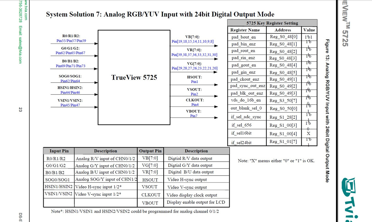
finally found where this is documented buried in the registers definitions - so basically all the digital RGB I/O pins can be used as a 24bit output of the test bus, but only VB3 is connected on the GBS so you're just using test bus output bit 3 for the v-sync pulsesrama wrote:The digital I/O pins are those 3 x 8 pins that can be digital video inputs or digital video outputs.
The GPIO are something else entirely, and I don't actively use any of those.
For separate sync inputs, I don't measure the interval. I don't have to, because I just bypass everything anyway.
The output timing is exactly the input timing
But the test bus is wired to a ton of data sources. I'm sure there's another VSync interval in there to measure.
I got confused and thought maybe you meant GPIO when you said digital I/O because the main datasheet makes no mention of test bus output pins anywhere I was able to find
-
rama
- Posts: 1373
- Joined: Wed Mar 08, 2017 3:15 pm
Re: GBS 8200/8220 CFW Project
Yeah, though I haven't tried to figure out how the other pins relate to the test bus data.
I can see that it has some internal timing and updates itself regularly.
It's totally unknown how that timing works, and there are some cases where I'd like to know if the data on the test bus is stale or not.
My guess is that it updates on the HSync event, but I'm not sure.
If it is the HSync, an I2C read can potentially read stale results. There is 64 microseconds. Not much, but maybe 2 reads fit in there.
Unrelated, but I thought it was remarkable:
Those pin drivers for the digital I/O are powerful! They can push very high frequency flanks out through traces and cables, and they still arrive at the ESP8266 as square waves. Talking like 50Mhz here..
Oh and yeah, be glad the register definition at least mentions a few test bus register bits.
There is nothing else on the thing, and all I know is reversed by random pokes and watching the reaction ><
-
rama
- Posts: 1373
- Joined: Wed Mar 08, 2017 3:15 pm
Re: GBS 8200/8220 CFW Project
maxtherabbit:
Do you have experience constructing digital video stuff?
If I wanted to try receiving digital RGB (say spliced off from a PSX's DAC into the GBS), would it suffice to connect just a couple color bits and the required timing signals?
I think I can manage soldering 5 or 6 mini wires for a functionality test. The full 3x8 + timing set is too much though :p
-
maxtherabbit
- Posts: 1763
- Joined: Mon Mar 05, 2018 4:03 pm
Re: GBS 8200/8220 CFW Project
I don't, only theoryrama wrote:maxtherabbit:
Do you have experience constructing digital video stuff?
If I wanted to try receiving digital RGB (say spliced off from a PSX's DAC into the GBS), would it suffice to connect just a couple color bits and the required timing signals?
I think I can manage soldering 5 or 6 mini wires for a functionality test. The full 3x8 + timing set is too much though :p
my understanding is all you need is clock, color bits, and HV sync - your test should work
-
rama
- Posts: 1373
- Joined: Wed Mar 08, 2017 3:15 pm
Re: GBS 8200/8220 CFW Project
Yeah, I guess I actually need to build something to know if it's feasible.
A PSX digital to pixel perfect scaled VGA with auto format switching (320px and 256px wide games, 384 is also used) would be awesome, I think.
Also, the quality would probably be indistinguishable from an emulator, at least up to 1280x :p
A PSX digital to pixel perfect scaled VGA with auto format switching (320px and 256px wide games, 384 is also used) would be awesome, I think.
Also, the quality would probably be indistinguishable from an emulator, at least up to 1280x :p
-
benryves
- Posts: 31
- Joined: Sun Jan 27, 2019 12:32 am
Re: GBS 8200/8220 CFW Project
I've been fiddling around with the GBS-8200 and gbs-control for a couple of days now and am very impressed, so thank you very much for your hard work to everyone involved in the project.
My TV doesn't like the default modes over VGA (with the exception of 640x480, which works out as 720x576@50 for me - presumably as I'm a PAL user) so I'm using a Mini VGA2HDMI to convert the signal to HDMI. All in all I measure 2-3 frames of lag, which I can't personally notice when playing (unlike my cheap generic SCART to HDMI box which I've measured at 7-8 frames of lag on the same TV).
I still have some issues with faint noise but I think that's from my current power supply. When I plug the GBS-8200 and Mini VGA2HDMI into a powered USB hub instead I only have very faint shimmering noise in the background but the hub doesn't provide enough power to reliably power the NodeMCU (the web interface drops out). I did initially have extremely bad noise (scrolling diagonal bands moving through the image) but this all seemed to come from the NodeMCU which shares the same power as the GBS-8200 (if I let the NodeMCU initialise the GBS-8200 and then yanked it out of the board the noise entirely vanished). I fixed it by soldering a 100uH inductor in series with the power into the NodeMCU; I'm not sure if this is the correct solution but it completely fixed the issue and it's the only inductor I had in my parts bin!
I'm one of the few weirdos left using Windows Phone which means that I couldn't get the web interface to work as I have IE11 which does not support the "for (let item of collection)" construct. In case anyone else on Windows was looking to make any changes to the webui.html I've left some notes below:
Spoiler
The command to create the webui_html.h is documented in the gbs-control.ino, but the 'single quotes' will need to have changed to "double quotes":
You will also need the appropriate Unix-like programs (gzip, rm, sed etc) installed somewhere in your path. I had most of them already thanks to WinAVR bundling most of them however its version of sed seemed to be out of date (it didn't like the -i parameter) and so I installed an updated version from the gnuwin32 project. xxd is included in the Windows version of vim.
One thing that really threw me is that the Unix-style LF line endings was preventing something from working properly - after recompiling the project the web interface would refuse to load with the browser complaining about an invalid compression scheme. Opening and re-saving the webui.html with Windows-style CR LF line endings before converting to webui_html.h fixed this issue.
The "for" constructs could then be changed from
to
Change variable names where appropriate - I needed to change three such loops. Clunky code, sure, but cheaper than buying a new phone and more practical than having to run to my PC on the other side of my flat every time I wanted to make a settings change.
Code: Select all
gzip -c9 webui.html > webui_html && xxd -i webui_html > webui_html.h && rm webui_html && sed -i -e "s/unsigned char webui_html\[]/const char webui_html[] PROGMEM/" webui_html.h && sed -i -e "s/unsigned int webui_html_len/const unsigned int webui_html_len/" webui_html.hOne thing that really threw me is that the Unix-style LF line endings was preventing something from working properly - after recompiling the project the web interface would refuse to load with the browser complaining about an invalid compression scheme. Opening and re-saving the webui.html with Windows-style CR LF line endings before converting to webui_html.h fixed this issue.
The "for" constructs could then be changed from
Code: Select all
for (let button of presetButtonList) {
	// code
}Code: Select all
[].forEach.call(presetButtonList, function(button) {
	// code
});-
rama
- Posts: 1373
- Joined: Wed Mar 08, 2017 3:15 pm
Re: GBS 8200/8220 CFW Project
Hey,
quite a few talking points here. Let's see.. :p
First of all, I use Windows as well. For dev stuff I prefer a Linux environment though, and Babun offers an almost native experience.
http://babun.github.io/
You get a shell and very well working integration.
Then there's your power issues.
You shouldn't need an inductor, and as long as you get noise without it, something must be wrong.
Do you power the ESP8266 board via its VIN, or directly via the GBS 3.3V line?
It's recommended to use a 5V to 9V supply to the GBS and VIN on the ESP8266 method.
Each boards regulators will take that to their required 3.3V.
The power supply should be able to deliver 5W (5V / 1A), but higher specs often mean a better quality.
(So just don't use a $1 supply ;p)
If you have a 3.3V connection between the GBS and the ESP8266 board, remove it. The supplies should be separated.
Regarding IE support:
Sorry to have you go through the extra steps. The "let" version has been tested and works well.
I'd like to keep using it, seeing as the IE problem will solve itself in the near future (as MS has finally given up), and generally, once you start trying to support IE, there's no return to sanity
Finally:
Your TV doesn't work with 1280x720@50 over VGA?
I was hoping that this would be supported at least. Maybe 1080p is..
Edit:
The web ui is notoriously finicky. I'm battling SDK bugs, bad WiFi conditions (from the near proximity of the antenna to the scaler chip) and inexperience on my side.
I'll get it reliable one day, but until then, don't assume it will work without issue ;p
Right now it looks like an initial gbscontrol.local lookup takes forever. It may be a problem where the ESP8266 doesn't reply to ARP requests.
-
rigues
- Posts: 27
- Joined: Thu May 17, 2018 5:05 pm
Re: GBS 8200/8220 CFW Project
Hi Rama,
Rigues back again with weird issues
I have been doing A LOT of testing of my GBS-Control setup with different devices, especially MSX-Based computers, using a RGB adapter I built (based on IL1883, a low-power LM1881 clone). The advantage of using the IL1883 on the RGB adapter is that it is so low-power that it can be powered from the ~3V on the "Slow Switch" pin on the RGB port, eliminating the need for a separate power source.
Anyway, the adapter/GBS combo works GREAT on most of the machines (13 tested so far), from multiple manufacturers (Sony, Panasonic, Toshiba, Sanyo, Philips, etc). However, on some of them the image occasionally blinks for a fraction of a second. I managed to capture this on video during one of the tests, linked below. The machines affected have nothing in common: different manufacturer (Sony and Gradiente), different video standards (NTSC on Sony, PAL-M on Gradiente) and video circuits (Sony follows the MSX standard, Gradiente has some differences on pinout). I thought about this being a power issue, but even with external power the problem persists on these machines.
Do you have any idea on what could be causing the issue? The number of machines affected is low (2 out of 13), but this has been puzzling me.
Link to the video: https://youtu.be/TG7ld1LdkDM
Also, a tip: during my testing I found that on some machines I couldn't get a video signal at all. After some experimentation, me and a friend determined that replacing the 100 Ohm resistor on the sync inputs with a 3V3 Zener diode + 4K7 resistor pair solved the problem and increased compatibility. The diode keeps the voltages on the "safe" level for the GBS. Also, I have seen no negative effects of this change on other MSX machines or consoles like the Sega Mega Drive and Sega Saturn.
Here is the list of the "certified" machines:
= Panasonic =
FS-A1
FS-A1 WSX
FS-A1 ST
FS-A1 GT
= Sony =
HB-F1XV
HB-F900
= Toshiba =
HX-22
= Sanyo =
PHC-70FD - For this one to work the replacement of the 100 Ohm resistor with the 4K7 + Zener pair on the sync inputs of the GBS was needed.
= Philips =
NMS-8245. OK both at native 50 Hz and forced 60 Hz
Also, the MA-20 "version up adapter" (upgrade cartridge from MSX to MSX2) works fine.
Regards,
-
rama
- Posts: 1373
- Joined: Wed Mar 08, 2017 3:15 pm
Re: GBS 8200/8220 CFW Project
Glad to hear that so many machines work fine.
Did you check the terminal when a video "hickup" is produced? If the terminal / web ui console prints a dot ( . ), then the issue was with the sync processor.
If there's nothing, then the issue is with the digital processing, maybe the IF unit.
I've seen those, by the way, but could never reproduce them reliably enough to even begin debugging :/
Your diode is from Sync to Gnd, I assume?
What would the effect of this diode resistor chain be.. I find it hard to predict how the waveform would change. Got any scope results?
Oh and to everyone who wanted it:
1080p support is in. Go wild!