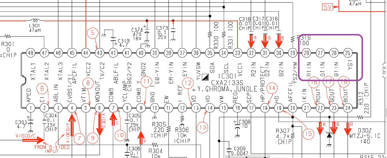
Umm feed some +v into YS1?
I fail to see the confusion this is a really straight forward jungle.
TV RGB mod thread
-
MarkOZLAD
- Posts: 1040
- Joined: Thu May 18, 2017 12:39 pm
Re: TV RGB mod thread
Sorry, I missed that from Mike. If he's tried it and it doesn't work that answers my query.dakattack wrote:earlier in the thread,MarkOZLAD wrote:
I wish I could get my hands on one just so I could try using the other RGB input....
Don't think I'll find any in Australia.I thought the v42 would be the same way? Is there a workaround that allows RGB1 to function?mikejmoffitt wrote:Regarding the RGB1 input on the S42's jungle IC, the microcontroller must first enable this input. Just wiring to it won't work (which I tried).
Also if anyone can tell me if K-SCARTX-024 from Mouser would be acceptable to use as the mounted input for the TV, that would be awesome too. Thanks.
___________________________________________________
MarkOZLAD
OSD/External RGB Mux Diagram
OSD/External RGB Mux Resistor Value Table 0.7Vp-p : 0.5Vp-p
"Imagine toggle switch OSD modding a TV in 2019" - maxtherabbit
MarkOZLAD
OSD/External RGB Mux Diagram
OSD/External RGB Mux Resistor Value Table 0.7Vp-p : 0.5Vp-p
"Imagine toggle switch OSD modding a TV in 2019" - maxtherabbit
-
Pikkon

- Posts: 129
- Joined: Tue May 26, 2015 6:25 am
- Location: Florida
Re: TV RGB mod thread
Hmm,wonder if the rgb could be enabled via the service menu,think my buddy has the same tv,I did the same thing on a crt when I modded for component so it's worth a try.
Last edited by Pikkon on Wed Oct 04, 2017 2:56 am, edited 1 time in total.
-
MarkOZLAD
- Posts: 1040
- Joined: Thu May 18, 2017 12:39 pm
Re: TV RGB mod thread
Syntax wrote:Umm feed some +v into YS1?
I fail to see the confusion this is a really straight forward jungle.
I'm backing away now before I make even more a fool of myself!
___________________________________________________
MarkOZLAD
OSD/External RGB Mux Diagram
OSD/External RGB Mux Resistor Value Table 0.7Vp-p : 0.5Vp-p
"Imagine toggle switch OSD modding a TV in 2019" - maxtherabbit
MarkOZLAD
OSD/External RGB Mux Diagram
OSD/External RGB Mux Resistor Value Table 0.7Vp-p : 0.5Vp-p
"Imagine toggle switch OSD modding a TV in 2019" - maxtherabbit
-
rx7turbo233

- Posts: 40
- Joined: Wed Sep 20, 2017 3:59 am
Re: TV RGB mod thread
cant find this ic data sheet la76170n jungle if anyone can help thanks
-
rx7turbo233
- Posts: 40
- Joined: Wed Sep 20, 2017 3:59 am
Re: TV RGB mod thread
i found it its the same as a LA76075 i cross refrenced them and found that this one is the same as the la76170n
-
dakattack
- Posts: 7
- Joined: Tue Oct 03, 2017 5:11 am
Re: TV RGB mod thread
I am new to this, so I am asking more than anything. mikejmoffitt tried to use RGB1 on the KV-27S42 featured in the OP that has a board just like this. I am assuming that he remembered to tie 5V to YS1. He ended up using RGB2 because he said RGB1 had to be enabled by the microcontroller. My question was if anyone knows a way to successfully use RGB1 on a board like this, because according to previous information in the thread, it is not as simple as plugging everything in. Again, I've never done this myself so I am looking to you, the expertsSyntax wrote:Umm feed some +v into YS1?
I fail to see the confusion this is a really straight forward jungle.
-
Syntax

- Posts: 1827
- Joined: Wed Aug 09, 2017 12:10 am
- Location: Australia
Re: TV RGB mod thread
Pin 36 - YUVSW looks interesting.
I'd wire a 10k pot to that while having YS1 high and see if it switches YS1 from YUV to RGB.
Haven't looked at the jungke pdf yet sorry.
I'd wire a 10k pot to that while having YS1 high and see if it switches YS1 from YUV to RGB.
Haven't looked at the jungke pdf yet sorry.
-
mikejmoffitt

- Posts: 629
- Joined: Fri Jan 08, 2016 7:26 am
- Location: Tokyo, Japan
Re: TV RGB mod thread
IIRC yes I'd tried RGB1 and YS1, and there was no change. I didn't look into what MCU hacks would need to be done, or if the firmware is even off-chip and/or can be dumped. You could grab a microcontroller and wire in I2C to talk to the jungle maybe, but at that point I'm just not as really interested. Give it a try, please post results if anything good happens.

-
Syntax
- Posts: 1827
- Joined: Wed Aug 09, 2017 12:10 am
- Location: Australia
Re: TV RGB mod thread
Does anyone know the correct way to combine the green channel and sync to create a sync on green RGB signal?
I connected c sync to green and plugged it into the component rca of a hd crt and got a solid picture but with a reddish hue.
I connected c sync to green and plugged it into the component rca of a hd crt and got a solid picture but with a reddish hue.
-
MarkOZLAD
- Posts: 1040
- Joined: Thu May 18, 2017 12:39 pm
Re: TV RGB mod thread
Maybe this link will help.Syntax wrote:Does anyone know the correct way to combine the green channel and sync to create a sync on green RGB signal?
I connected c sync to green and plugged it into the component rca of a hd crt and got a solid picture but with a reddish hue.
This RGB to component converter might also give you some pointers.
___________________________________________________
MarkOZLAD
OSD/External RGB Mux Diagram
OSD/External RGB Mux Resistor Value Table 0.7Vp-p : 0.5Vp-p
"Imagine toggle switch OSD modding a TV in 2019" - maxtherabbit
MarkOZLAD
OSD/External RGB Mux Diagram
OSD/External RGB Mux Resistor Value Table 0.7Vp-p : 0.5Vp-p
"Imagine toggle switch OSD modding a TV in 2019" - maxtherabbit
-
cyborc

- Posts: 308
- Joined: Wed Mar 25, 2009 6:26 am
- Location: USA
Re: TV RGB mod thread
What would I do if the jungle expects 2.5v for the RGB inputs? Unless I'm reading this wrong, which is entirely possible...

-
MarkOZLAD
- Posts: 1040
- Joined: Thu May 18, 2017 12:39 pm
Re: TV RGB mod thread
Ahhh the Panasonic AN5693 chip....From an MX-4 chassis?cyborc wrote:What would I do if the jungle expects 2.5v for the RGB inputs? Unless I'm reading this wrong, which is entirely possible...
I was looking into one of these the other day. When I read it I too assumed it means it requires a 2.5V point to point voltage for the RGB inputs. Was thinking of picking up a beautiful example of this set to mod but when I saw that I baulked.
I would think you would need to amplify your RGB signals to mod this set but I am by no means certain. It may be that it can accept RGB inputs with voltages up to 2.5V and can auto adjust. I don't know.
Find out would ya
___________________________________________________
MarkOZLAD
OSD/External RGB Mux Diagram
OSD/External RGB Mux Resistor Value Table 0.7Vp-p : 0.5Vp-p
"Imagine toggle switch OSD modding a TV in 2019" - maxtherabbit
MarkOZLAD
OSD/External RGB Mux Diagram
OSD/External RGB Mux Resistor Value Table 0.7Vp-p : 0.5Vp-p
"Imagine toggle switch OSD modding a TV in 2019" - maxtherabbit
-
cyborc
- Posts: 308
- Joined: Wed Mar 25, 2009 6:26 am
- Location: USA
Re: TV RGB mod thread
That's what I was thinking, but I am pretty clueless when it comes to amplifying video signals.MarkOZLAD wrote:Ahhh the Panasonic AN5693 chip....From an MX-4 chassis?cyborc wrote:What would I do if the jungle expects 2.5v for the RGB inputs? Unless I'm reading this wrong, which is entirely possible...
I was looking into one of these the other day. When I read it I too assumed it means it requires a 2.5V point to point voltage for the RGB inputs. Was thinking of picking up a beautiful example of this set to mod but when I saw that I baulked.
I would think you would need to amplify your RGB signals to mod this set but I am by no means certain. It may be that it can accept RGB inputs with voltages up to 2.5V and can auto adjust. I don't know.
Find out would ya
-
MarkOZLAD
- Posts: 1040
- Joined: Thu May 18, 2017 12:39 pm
Re: TV RGB mod thread
If I could've got the set for free I would do the same thing!cyborc wrote:I don't actually have the monitor in hand otherwise I'd just throw 0.7v video at it and see what happened.
___________________________________________________
MarkOZLAD
OSD/External RGB Mux Diagram
OSD/External RGB Mux Resistor Value Table 0.7Vp-p : 0.5Vp-p
"Imagine toggle switch OSD modding a TV in 2019" - maxtherabbit
MarkOZLAD
OSD/External RGB Mux Diagram
OSD/External RGB Mux Resistor Value Table 0.7Vp-p : 0.5Vp-p
"Imagine toggle switch OSD modding a TV in 2019" - maxtherabbit
-
Syntax
- Posts: 1827
- Joined: Wed Aug 09, 2017 12:10 am
- Location: Australia
Re: TV RGB mod thread
Playing with an LG set I just found and it seems it has a place to solder a scart plug.
After looking closely at the traces I found the OSD is mixed directly to the jungle output with diodes in between.
Closer inspection showed that the scart RGB lines wanted resistors inline, which confused me as the jungle in question wanted .7vpp
So I hunted down the chassis pdf and found that this chassis came out with teletext that is mixed directly into the scart RGB inputs, also with diodes.
Here's a link to the chassis pdf, it has resistor and cap values, you'll notice that the OSD actually has inline chokes instead of resistors.
http://s000.tinyupload.com/index.php?fi ... 2497039237
Maybe we can work off this, copy it or find a formula of resistor/choke/diodes to either mix OSD and RGB lines together or move the OSD lines to the output side of the jungle.(bypassing any menu settings for OSD I'm sure)
For reference
Teletextboard RGB outputs (not sure of this chips original vpp output)
Inline 1.6k resistor THEN 1.6k ground termination THEN 1N4148 diode Then ties to the ext RGB lines at the ceramic cap THEN jungle.
EXT RGB inputs
75ohm ground termination THEN 1k inline resistor THEN the ceramic cap THEN jungle.
-
rx7turbo233
- Posts: 40
- Joined: Wed Sep 20, 2017 3:59 am
Re: TV RGB mod thread
Found a old pioneer tvm 252 monitor trying to look for a manual for it but can't find anywhere of anyone can help that would be cool trying to find out what I can. And why able to be done to it
-
Syntax
- Posts: 1827
- Joined: Wed Aug 09, 2017 12:10 am
- Location: Australia
Re: TV RGB mod thread
Search for the chassis number
-
buttersoft

- Posts: 377
- Joined: Sun Jul 24, 2016 7:49 am
Re: TV RGB mod thread
THS7314 or 7316 should do a good enough job. I know someone who modded a 2.5Vp-p RGB input Panasonic that way, and it looks amazing.cyborc wrote: That's what I was thinking, but I am pretty clueless when it comes to amplifying video signals.I'm not sure of the chassis, but it's from a panasonic CCTV monitor. I don't actually have the monitor in hand otherwise I'd just throw 0.7v video at it and see what happened.
-
MarkOZLAD
- Posts: 1040
- Joined: Thu May 18, 2017 12:39 pm
Re: TV RGB mod thread
FYI if you want to see a similar pattern on a Sony chassis check out the BG-1S chassis. External RGB (usually unused) and OSD muxed post jungle.Syntax wrote:Maybe we can work off this, copy it or find a formula of resistor/choke/diodes to either mix OSD and RGB lines together
Easiest mod ever and has perfect OSD.
___________________________________________________
MarkOZLAD
OSD/External RGB Mux Diagram
OSD/External RGB Mux Resistor Value Table 0.7Vp-p : 0.5Vp-p
"Imagine toggle switch OSD modding a TV in 2019" - maxtherabbit
MarkOZLAD
OSD/External RGB Mux Diagram
OSD/External RGB Mux Resistor Value Table 0.7Vp-p : 0.5Vp-p
"Imagine toggle switch OSD modding a TV in 2019" - maxtherabbit
-
arithmaldor

- Posts: 124
- Joined: Wed Jun 07, 2017 8:39 pm
Re: TV RGB mod thread
Alright everyone I need your help, I'm at my wit's end. I am attempting to mod a Toshiba CF19H25 to use in an arcade cabinet.
After opening it up I found that the jungle chip was TA1282N. This is all of the information that I could find on it:

So pins 14-17 look like what we want. I desoldered these pins and pulled them out of the board.
I wired my input, vga from a SNES via gscartsw 3.4 into one end of a 4pdt switch, along with 3.3v from pin 18. I wired the original OSD signals from the bottom of the board to the other side of the switch. Video ground was wired to pin 13. The output went from the 4pdt switch to the pins 14-17. The signals going to 15-17 (RGB) each had a 75 ohm resistor to ground, followed by a 0.1 uF ceramic capacitor in line. The sync was wired to the underside of the board into the composite video input.
I turned on the TV, turned on the SNES, and voila! perfect image, no adjustments needed. I decided I was going to take out the 4pdt switch as it would be dedicated for a cab. I discharged the tube and unplugged the anode cap. The next day I plugged the anode cap back in and went to show it to someone and the colors were off, like one was missing or something. I thought maybe one of the lines had disconnected and that it would be fixed when I reconnected everything.
Fast forward, the tube is now in the arcade cabinet. I wired pin 18 straight to pin 14, then wired a female SCART head (with 3 resistors to ground and a 0.1uF cap in line for each of the RGB lines in the head) to the inputs 15-18 and 13 for ground, sync wired to the composite input. I connected my SNES via SCART into this, turned on the TV, then turned on the SNES. Mario World has all of the correct colors, but every white is missing.
How do I fix this? I would move on and try to find another TV to try it on, but I had it working briefly and it looked so good, so I really would like to get this working.
The female SCART cable is very short, about 4 inches, and the capacitors are wired directly to the pins 15-18. The resistors are still in the SCART head.
I tried wiring sync to pin 43 on the jungle (Y in) but now the picture has no sync. I can see through the garble that red green and blue are still there, but white is still missing. Any advice would be appreciated. I'm going to keep an eye out for any other 19" and try again if this doesn't work out.
Thanks to all, please help!!!
After opening it up I found that the jungle chip was TA1282N. This is all of the information that I could find on it:
So pins 14-17 look like what we want. I desoldered these pins and pulled them out of the board.
I wired my input, vga from a SNES via gscartsw 3.4 into one end of a 4pdt switch, along with 3.3v from pin 18. I wired the original OSD signals from the bottom of the board to the other side of the switch. Video ground was wired to pin 13. The output went from the 4pdt switch to the pins 14-17. The signals going to 15-17 (RGB) each had a 75 ohm resistor to ground, followed by a 0.1 uF ceramic capacitor in line. The sync was wired to the underside of the board into the composite video input.
I turned on the TV, turned on the SNES, and voila! perfect image, no adjustments needed. I decided I was going to take out the 4pdt switch as it would be dedicated for a cab. I discharged the tube and unplugged the anode cap. The next day I plugged the anode cap back in and went to show it to someone and the colors were off, like one was missing or something. I thought maybe one of the lines had disconnected and that it would be fixed when I reconnected everything.
Fast forward, the tube is now in the arcade cabinet. I wired pin 18 straight to pin 14, then wired a female SCART head (with 3 resistors to ground and a 0.1uF cap in line for each of the RGB lines in the head) to the inputs 15-18 and 13 for ground, sync wired to the composite input. I connected my SNES via SCART into this, turned on the TV, then turned on the SNES. Mario World has all of the correct colors, but every white is missing.
How do I fix this? I would move on and try to find another TV to try it on, but I had it working briefly and it looked so good, so I really would like to get this working.
The female SCART cable is very short, about 4 inches, and the capacitors are wired directly to the pins 15-18. The resistors are still in the SCART head.
I tried wiring sync to pin 43 on the jungle (Y in) but now the picture has no sync. I can see through the garble that red green and blue are still there, but white is still missing. Any advice would be appreciated. I'm going to keep an eye out for any other 19" and try again if this doesn't work out.
Thanks to all, please help!!!
-
Syntax
- Posts: 1827
- Joined: Wed Aug 09, 2017 12:10 am
- Location: Australia
Re: TV RGB mod thread
Had a similar issue with an LG today, colors were kinda on and off, turns out the board had flexed somewhere along the line and cracked the super thin solder on the jungle legs.
Reflowing the legs fixed this. It was really hard to spot.
Reflowing the legs fixed this. It was really hard to spot.
-
arithmaldor
- Posts: 124
- Joined: Wed Jun 07, 2017 8:39 pm
Re: TV RGB mod thread
I've checked the jungle IC, put new solder on all the legs and the problem remains.
-
Syntax
- Posts: 1827
- Joined: Wed Aug 09, 2017 12:10 am
- Location: Australia
Re: TV RGB mod thread
Is composite stuffed also or just rgb?
-
Syntax
- Posts: 1827
- Joined: Wed Aug 09, 2017 12:10 am
- Location: Australia
Re: TV RGB mod thread
Pretty sure I just nailed mixing OSD and Console RGB on the Sony BG range.
https://www.electronica-pt.com/esquema/ ... nfo/29596/
What I did was remove the OSD inline 3.9k resistors and bridged the pads. (R024 R025 R026)
Then I removed the original coupling caps and termination resistors near the jungle. (R063 R064 R065) (C318 C319 C320)
I replaced them with 100n(104) ceramic caps and 75 ohm resistors.
My theory behind this was the original 470ohm OSD ground termination was weak because the OSD inline resistor was so strong. (Making the OSD signal weak)
I needed to beef up the OSD signal to get it ready for a strong 75ohm ground termination, so I put a triple gang 10k pot in the OSD inline resistors place to see where the sweet spot was.
Turns out it was ground zero..
I'm not sure if this is safe but I have tested it for about 30 minutes now and the console picture is fine, my SNES hasn't blown up and the menu is the same strength regardless of the console being plugged in or not.
Ill continue to use this method for as many sets as I can, and report with the results.
Time to reclaim some of them 4PDT switches hey?
Edit..
Scart cables with termination resistors screw with the menu slightly.
-
MarkOZLAD
- Posts: 1040
- Joined: Thu May 18, 2017 12:39 pm
Re: TV RGB mod thread
Great work indeed!Syntax wrote:Pretty sure I just nailed mixing OSD and Console RGB on the Sony BG range.
https://www.electronica-pt.com/esquema/ ... nfo/29596/
What I did was remove the OSD inline 3.9k resistors and bridged the pads. (R024 R025 R026)
Then I removed the original coupling caps and termination resistors near the jungle. (R063 R064 R065) (C318 C319 C320)
I replaced them with 100n(104) ceramic caps and 75 ohm resistors.
My theory behind this was the original 470ohm OSD ground termination was weak because the OSD inline resistor was so strong. (Making the OSD signal weak)
I needed to beef up the OSD signal to get it ready for a strong 75ohm ground termination, so I put a triple gang 10k pot in the OSD inline resistors place to see where the sweet spot was.
Turns out it was ground zero..
I'm not sure if this is safe but I have tested it for about 30 minutes now and the console picture is fine, my SNES hasn't blown up and the menu is the same strength regardless of the console being plugged in or not.
Ill continue to use this method for as many sets as I can, and report with the results.
Time to reclaim some of them 4PDT switches hey?
Edit..
Scart cables with termination resistors screw with the menu slightly.
How does the brightness level of the RGB compare to Composite or other inputs?
___________________________________________________
MarkOZLAD
OSD/External RGB Mux Diagram
OSD/External RGB Mux Resistor Value Table 0.7Vp-p : 0.5Vp-p
"Imagine toggle switch OSD modding a TV in 2019" - maxtherabbit
MarkOZLAD
OSD/External RGB Mux Diagram
OSD/External RGB Mux Resistor Value Table 0.7Vp-p : 0.5Vp-p
"Imagine toggle switch OSD modding a TV in 2019" - maxtherabbit
-
Syntax
- Posts: 1827
- Joined: Wed Aug 09, 2017 12:10 am
- Location: Australia
Re: TV RGB mod thread
They are all the same brightness level, this set does not have component only svideo.
Csync must be used in either Luma or Comp to avoid the screen shift.
Csync must be used in either Luma or Comp to avoid the screen shift.
-
MarkOZLAD
- Posts: 1040
- Joined: Thu May 18, 2017 12:39 pm
Re: TV RGB mod thread
Perfect result.Syntax wrote:They are all the same brightness level, this set does not have component only svideo.
Csync must be used in either Luma or Comp to avoid the screen shift.
___________________________________________________
MarkOZLAD
OSD/External RGB Mux Diagram
OSD/External RGB Mux Resistor Value Table 0.7Vp-p : 0.5Vp-p
"Imagine toggle switch OSD modding a TV in 2019" - maxtherabbit
MarkOZLAD
OSD/External RGB Mux Diagram
OSD/External RGB Mux Resistor Value Table 0.7Vp-p : 0.5Vp-p
"Imagine toggle switch OSD modding a TV in 2019" - maxtherabbit
-
xAzurexEonx
- Posts: 74
- Joined: Sun Aug 27, 2017 2:45 am
Re: TV RGB mod thread
Curious, how old of a TV would you believe this mod would work on?
-
Pikkon
- Posts: 129
- Joined: Tue May 26, 2015 6:25 am
- Location: Florida
Re: TV RGB mod thread
Awesome work Syntax,will give this a try on my trinitron and report back.