How to: Modding a Mayflash arcade stick

The place for all discussion on gaming hardware
User avatar
brokenhalo
Posts: 1392
Joined: Wed Mar 26, 2008 4:11 am
Location: philly suburbs

How to: Modding a Mayflash arcade stick

Post by brokenhalo »

there isn't nearly as much knowledge on how to mod sticks on this site as there is on other sites, so i decided to make a quick tutorial. hopefully this helps a few people out.

Image

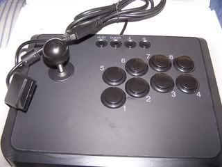
So this is the mayflash usb fighting stick. the pcb inside is compatible with ps2/ps3/pc (xp and vista). the stock parts are pretty crap. the stick is really loose and unresponsive, and the buttons are plunger style buttons that miss inputs real easy if your pushing buttons real fast.

Image

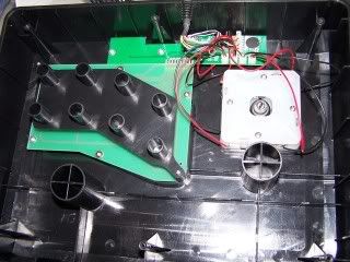
this is what you've got on the inside. you'll want to remove the 4 screw that hold the stick down, then unscrew the balltop to get the stock stick out. the red wires are ground (it's a common ground pcb) so you can snip them off altogther. cut off the black wires as close to the stick as possible so you can use them later. (edit: this isn't always the case with the wires. i've seen sticks where the colors were mixed up, so check with a multimeter to figure out which 4 are ground.) then unscrew the black plastic plate that holds the button pcb down.

Image

the button pcb needs to come out. you can desolder it where the pins meet the main pcb, but it's easier to just bend the pcb up and break the prongs off. now remove the stock buttons and the pcb.

Image

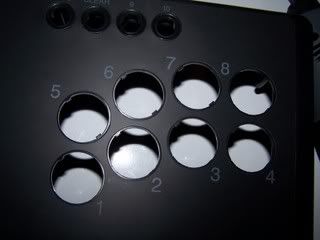
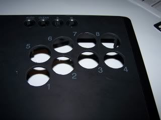
you'll need to file out the button holes from 28mm to 30mm. first thing you'll want to do is file down the tabs in each hole (pic above has 5 of the tabs already filed down). then file out the holes to the proper size. keep a button on hand for test fitting purposes. if you have a dremel and a griniding bit this will go much fatser.

Image

after dremaling. not a huge difference.

Image

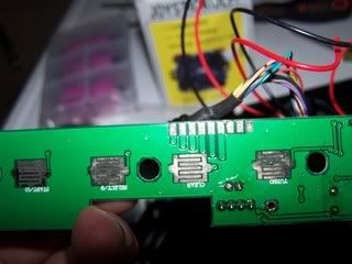
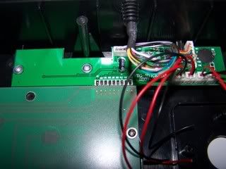
so that's the underside of the pcb. just above the "clear" button you'll see 9 small soldering pads. these would be buttons 1-8 and then ground. it's a pretty tight space, but you'll need to solder wires to those tabs.
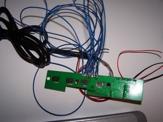
Image

done!

Image

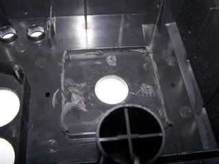
back to the inside of the stick. to mount the jlf i put a cutting wheel in my dremel and cut off the little tabs the stock stick screwed into, and part of the plastic wall that surrounded the stock stick. this will allow you to undermount the jlf right up against the plastic. you'll also want to use the jlf mounting plate to help you line up your screw holes. those little black marks in the above pic are where i drilled. now it's time to mount the parts.

Image

i decided to remove the top sticker and paint the whole case. 2 coats of plastic primer and a coat of textured gray. i'm a total novice at painting, but it came out pretty good.

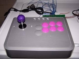
as far as parts, i used a sanwa jlf with a violet seimitsu bubble-top, sanwa obsn-30's (violet) and sanwa button plugs.

Image

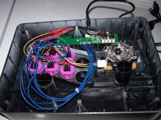
a messy wiring shot. wiring is fairly simple though. 5 lines for your stick including ground, and 6 wires for the face buttons.

Image

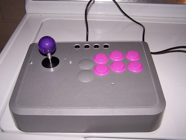
the finished stick. altogether, this is a fairly easy mod, so long as you have some experience in soldering. if you have any questions, i'll try to answer as best i can.
Last edited by brokenhalo on Mon Jan 21, 2013 3:44 am, edited 1 time in total.
User avatar
emphatic
Posts: 7920
Joined: Mon Aug 18, 2008 3:47 pm
Location: Alingsås, Sweden
Contact:

Post by emphatic »

Nice guide.

Emph
Image | My games - http://www.emphatic.se | (Click) I have YEN stickers for sale
RegalSin wrote:Street Fighters. We need to aviod them when we activate time accellerator.
stormrider85
Posts: 2
Joined: Wed Nov 05, 2008 9:31 pm

mayflash origianl

Post by stormrider85 »

sorry to post if this is an old thread, but i got a mayflash just yesterday and i have noticed it to be a little unresponsible when you play fast etc, i was wondering if you would know any way i could mod it at home without buying new parts, possibly some tricks you would know to make it respond a little better.

ive seen some people on youtube use electrical tape on their joystick to maker the distance of the moves short and also make it durable.

know any others, cause i dont want to buy any new parts.
User avatar
brokenhalo
Posts: 1392
Joined: Wed Mar 26, 2008 4:11 am
Location: philly suburbs

Re: mayflash origianl

Post by brokenhalo »

stormrider85 wrote:sorry to post if this is an old thread, but i got a mayflash just yesterday and i have noticed it to be a little unresponsible when you play fast etc, i was wondering if you would know any way i could mod it at home without buying new parts, possibly some tricks you would know to make it respond a little better.

ive seen some people on youtube use electrical tape on their joystick to maker the distance of the moves short and also make it durable.

know any others, cause i dont want to buy any new parts.
i guess you could try taping up the actuator to make it bigger and decrease the play, but honestly that stock stick is just a loose p.o.s. and you'll notice the buttons miss inputs if your trying to play something fast like tetris. best recommendation is to mod it. it's not too hard assuming you know how to solder and the stick and buttons will run you about $50.
stormrider85
Posts: 2
Joined: Wed Nov 05, 2008 9:31 pm

Post by stormrider85 »

would you use the same pcb and just buy new stick and buttons or geta new pcb?

also i just tried opening mine up but i cant seem to get the back panel open i took out the 2 screws and tried to wedge is out with a flat head screwdriver but it wont budge.

im scared im going to snap the body if i force it to much is there anything im missing, i assumed it was only the two screws i had to take out
MKL
Posts: 407
Joined: Wed Feb 02, 2005 9:33 pm
Location: Pordenone, Italy

Post by MKL »

stormrider85 wrote:also i just tried opening mine up but i cant seem to get the back panel open i took out the 2 screws and tried to wedge is out with a flat head screwdriver but it wont budge.

im scared im going to snap the body if i force it to much is there anything im missing, i assumed it was only the two screws i had to take out
In the second pic there are 6 screw pillars visible so the bottom panel will have 6 screws as is usual on sticks. If you don't see them I guess they will be under the rubber pads.
User avatar
brokenhalo
Posts: 1392
Joined: Wed Mar 26, 2008 4:11 am
Location: philly suburbs

Post by brokenhalo »

you can use the same pcb that is in there. read over the guide i posted up above very carefully and decide if you feel comfortable doing all this before you start. it isn't very hard, but you'll want some experience soldering as the pcb solder points are fairly small and very close together.

and there are 6 screws. you'll have to peel off the rubber feet on the bottom.
ViolentAJ
Posts: 14
Joined: Tue Jan 06, 2009 6:33 am

Post by ViolentAJ »

I just got one today, and I know little about saudering and the like. I do have a dremel tool, but I don't want to screw things up and I'm afraid that I will. For me, the stick works fine but the buttons respond rather slowly. Is there any workaround without having to mod the stick? I rly don't want to put out more money and I certainly don't want to foul up the equipment.
User avatar
brokenhalo
Posts: 1392
Joined: Wed Mar 26, 2008 4:11 am
Location: philly suburbs

Post by brokenhalo »

ViolentAJ wrote:I just got one today, and I know little about saudering and the like. I do have a dremel tool, but I don't want to screw things up and I'm afraid that I will. For me, the stick works fine but the buttons respond rather slowly. Is there any workaround without having to mod the stick? I rly don't want to put out more money and I certainly don't want to foul up the equipment.
the slow response on the buttons is indeed problematic. looking at the way that they function, i don't know if there would really be any way to fix them other than replacing them. maybe putting a heavy spring inside the button so it returns to the up position faster?
KBZ
Posts: 1256
Joined: Sat Mar 26, 2005 4:47 am

Post by KBZ »

doesn't the stick sit really high (tall) without a spacer?
=/
User avatar
brokenhalo
Posts: 1392
Joined: Wed Mar 26, 2008 4:11 am
Location: philly suburbs

Post by brokenhalo »

Kingbuzzo wrote:doesn't the stick sit really high (tall) without a spacer?
on the mod i did? yeah, but i like it that way better. if i was going to sell one i'd put it at the proper height.
grumbles
Posts: 1
Joined: Mon May 04, 2009 4:33 pm

Post by grumbles »

Nice guide Brokenhalo :)
Just a quick question on the wiring for the jlf stick.
Using the original 4 dual wires did you just attach one of each dual wires (red, i assume) to the the corresponding 5 pin wire and connect all the remaining 4 black wires (which I assume are the ground wires) to the ground 5 pin wire?
Hope this makes sense...
User avatar
brokenhalo
Posts: 1392
Joined: Wed Mar 26, 2008 4:11 am
Location: philly suburbs

Post by brokenhalo »

first, don't assume that all black are ground and all red are directional or vice versa. they seem to just wire them at random, but each pair will be a ground and a direction.

you've got the right idea though. each of the 4 directional wires will go to the corresponding jlf harness directional wire. as for the grounds, they are common so you can use any one of the 4 grounds and just snip off the other 3.
CptnAmerica
Posts: 5
Joined: Tue May 05, 2009 5:20 am

Post by CptnAmerica »

Thanks brokenhalo. I followed your instructions and was able to mod my own mayflash. I cheated a bit by not using spade connectors when indeed I had used barrier strips... ha ha, I'm a pirate! Also wanted to post up some pictures for people who are adament about cutting the PCB to wiring each ground separately. :) I used some non-used screw holes to mount the wire terminal strips so it stays snug inside the board (no vibrating noises either!).

For the joystick mount, I only filed down the restrictor gate so the screw head would fit into the restrictor gate. The whole joystick is untouched just in case I want to sell it back with a new restrictor gate at a future point or reuse it for my other joystick case. :) This is my first mod and for first timers like me using dremel, use the lowest speed to grind the button holes and take your time. Always do this in your back yard with eye protection.

Thanks again brokenhalo - kudos to you!

Note: I didn't clip the ground wires because if I change my mind to using something like a seimitsu then I probably need the ground wires... although since the last ground wire is clipped, I may be faced with some challenges.

YEA MY BALLTOP IS PINK BUT IT DISTRACTS MY FRIENDS WHILE I PWN THEM!!!

Image
Image
Image
User avatar
brokenhalo
Posts: 1392
Joined: Wed Mar 26, 2008 4:11 am
Location: philly suburbs

Post by brokenhalo »

^^^^ good job! glad my guide could be of help. the barrier strips are a little overkill, but if you want to dual-mod it down the line and throw a 360 pcb in as well it will make it that much easier.

and don't worry about the ground that you snipped. if you decide to swap in a joystick that doesn't use a 5-pin harness you can still use your one ground wire and just jump it from ground to ground on the joystick. just like how you jumped the ground to each button.
CptnAmerica
Posts: 5
Joined: Tue May 05, 2009 5:20 am

Post by CptnAmerica »

Hey Brokenhalo, i've been meaning to do a dual mod but I'm definitely having trouble finding a good guide on wiring.

I found one in SRK forums but it seems confusing. If you have the time, please take a look at this link -
http://forums.shoryuken.com/showthread.php?t=181539

Look at the second picture - It has ground in PINK which are not used... why did the author label it in the first place?

And also like the other guys in the forum, which no one had answers to - how do you wire the triggers as regular button? (I play neo geo games and I like to play with 4 buttons in a straight row, therefore wanting to wire all 8 buttons.)

Oh by the way - for noobs like me wondering where to get mayflash art - here it is:

http://frog3.free.fr/Stick_Arcade/mayflash_stick.psd
http://frog3.free.fr/Stick_Arcade/mayfl ... school.psd
http://frog3.free.fr/Stick_Arcade/mayfl ... -akuma.psd
http://frog3.free.fr/Stick_Arcade/mayfl ... ck_SF4.psd
http://frog3.free.fr/Stick_Arcade/mayfl ... Street.psd

Note these are huge photoshop PSD files - meaning if you save as jpeg or gif, you won't get the desired results. It'll end up as a huge blowup if you have converted into a jpeg and if you print it, obviously too big for your mayflash. So after you change the art in the PSD file, try to convert to PDF or something before heading out to kinkos or whatever shop - something that will retain the actual print size.

here are regular non-psd files:

http://img12.imageshack.us/gal.php?g=ma ... school.jpg
User avatar
brokenhalo
Posts: 1392
Joined: Wed Mar 26, 2008 4:11 am
Location: philly suburbs

Post by brokenhalo »

CptnAmerica wrote:I found one in SRK forums but it seems confusing. If you have the time, please take a look at this link -
http://forums.shoryuken.com/showthread.php?t=181539

Look at the second picture - It has ground in PINK which are not used... why did the author label it in the first place?
the grounds for the triggers aren't common to the grounds for everything else. so if you want to wire the triggers you have to use each triggers ground to got your trigger button. or at least thats' the way i understand it. if you want to test it, take a multimeter and check for continuity between on of the front ground points and your trigger ground.
how do you wire the triggers as regular button?
it depends on what sort of pcb you are working with. for the most part, you just desolder the trigger pot and solder in a resistor and it'll work. some of the newer madcatz cheapo pads require a voltage wiper because they work in reverse of how the normal triggers work.

http://forums.shoryuken.com/showthread.php?p=6466749

post 23 has a basic diagram of how it works on the majority of controllers.
if you don't want to muck about with triggers though you could always do a 7 button layout and wire it up like this

X Y Lb Rb
A B Rb
jorjet27
Posts: 6
Joined: Fri May 08, 2009 5:49 am

Post by jorjet27 »

Heya!
nice write up, i'm waiting for my mayflash to come in to the mail - then i'll get cracking!

just a question.
i've read that you have to cut the pcb (then directly solder to the switcheS) to make the joystick work, but with these guides you don't!

you even prove it to the people that are adamant about cutting the pcb.

so your sticks work flawless with only 1 ground connection? or are there additional mods to be performed?

Thanks!!
User avatar
brokenhalo
Posts: 1392
Joined: Wed Mar 26, 2008 4:11 am
Location: philly suburbs

Post by brokenhalo »

jorjet27 wrote:just a question.
i've read that you have to cut the pcb (then directly solder to the switcheS) to make the joystick work, but with these guides you don't!

you even prove it to the people that are adamant about cutting the pcb.
could you link to a guide that shows the pcb being cut? i'd be interested just to see what you are talking about.
so your sticks work flawless with only 1 ground connection? or are there additional mods to be performed?
yup, the joystick works fine with only the one ground connection being used. there is only one ground loop on the mayflaash pcb. you can use a multimeter to check continuity between the different ground points on the pcb and you will find that they are all connected.

good luck on the mod. post some pics when you are finished :D
jorjet27
Posts: 6
Joined: Fri May 08, 2009 5:49 am

Post by jorjet27 »

Here is the post about cutting the pcb traces.

But if you say connecting one ground connection is enough, i'll go with that!

Let me know what you think.

Thanks!
User avatar
brokenhalo
Posts: 1392
Joined: Wed Mar 26, 2008 4:11 am
Location: philly suburbs

Post by brokenhalo »

oh ok. i see what they are talking about. they are talking about cutting the traces on the sanwa jlf pcb to isolate each individual microswitch. you have to do this on the hori ex-2 and other non-common ground pcbs as well.

the only thing i can guess is that maybe there was a run of mayflash sticks that had a non-common ground pcb. but all the mayflash sticks that i've worked on have all been common ground. i guess check your grounds with a meter and make sure everything is common before you start modding. if your pcb is noncommon, i have a jlf pcb around somewhere that has the traces cut for a hori ex-2 install. i can post a pic if you need it.
jorjet27
Posts: 6
Joined: Fri May 08, 2009 5:49 am

Post by jorjet27 »

thanks, you are really helpful!

so to check if the mayflash pcb is common ground, i would use a multimeter and put one stick on one ground then use the other stick to check the other ground points, and if they all read the same value this means they are common ground?
User avatar
brokenhalo
Posts: 1392
Joined: Wed Mar 26, 2008 4:11 am
Location: philly suburbs

Post by brokenhalo »

most multimeters will have a setting for checking continuity that beeps if the circuit is closed.

http://www.protronics.com.au/howto.html#symbol

it's listed as audible continuity in the above chart. if you have your meter on this setting and touch the two probes together the meter will beep. this indicates that you have a continuous circuit between the two leads. so if you touch one probe to a ground on the the pcb and touch your lead to another ground on the board you should complete the circuit (or not) and hear the beep (or not).
jorjet27
Posts: 6
Joined: Fri May 08, 2009 5:49 am

Post by jorjet27 »

ah great! thats makes sense :)

another question, for the sanwa buttons how do you tell which prong is the signal and which one is the ground? I've had a look at them and i can't figure it out..

Thanks.
CptnAmerica
Posts: 5
Joined: Tue May 05, 2009 5:20 am

Post by CptnAmerica »

that's the best part! On the buttons itself, either can be ground or active. Note when you press the button it just connects the ground to the "hot" wire and therefore triggering the action corresponding in the video game.

Big lessons learned from modding -

1. Don't use fruity colors like me. If you don't know what you are doing with the colors, just stick with one color for both the Joystick ball top and all the buttons. With black joystick like mayflash, white color works well if you aren't decisive.

2. BIG LESSON LEARNED!!! You need to dremel the holes on the mayflash so the sanwa buttons fit all the way - the holes can't be so that it is giving a bit of pressure around the button. This happens when the hole is cut just "ALMOST BIG ENOUGH" just enough the buttons will fit into the mayflash. When this happens it creates pressure around the sanwa button and the buttons feels like hori - the button does not feel smooth as it should be and feels like HORI BUTTONS!!! Sounds wierd too. I figured this out because my retail bought sanwa stick (MAD CATZ TE stick) had a different button feel. To see what I mean, take sanwa button and wrap your index finger and thumb around the button (sort of like as if you were making a "OK" hand signal around the button). Give it a firm pressure and press the button. "OH MY" you say - it feels like HORI!!!

Moral of the story - cut big enough hole that the button clip will come all the way out and no sides are giving pressure to the button. But be careful of cutting hole too big or else your button will start rotating. As for me, best way to remediate this problem was getting threaded seimitsu buttons with locking nut (sanwa's locking nut may be too big i heard - rubbing against each other). :) good luck!
User avatar
StarCreator
Posts: 1941
Joined: Mon Jan 12, 2009 2:44 am
Location: Maryland, USA
Contact:

Post by StarCreator »

Sorry for bumping, but I wanted to point something out...

I just opened up a Mayflash myself, and the date printed on the main PCB is March 2009. I disassembled the lever and found Omron switches inside - pretty much the same switches you'd find in a JLF. Definitely Christmas in May...

Assuming that anyone doing a Mayflash mod finds the same thing I found, and wants to put a JLF in, it would be much easier to just remove the PCB-mounted switches in the JLF and swap in the stock switches. Much easier and less wasteful than breaking traces...

I'm not going to be doing this myself because I want to rewire the stick for DB15 and I have a LS-32-01 coming in for that purpose. I might have to order a flat mounting plate to go with it though, unless someone here has a decent method of getting an S mounting plate to work...
User avatar
brokenhalo
Posts: 1392
Joined: Wed Mar 26, 2008 4:11 am
Location: philly suburbs

Post by brokenhalo »

StarCreator wrote:Much easier and less wasteful than breaking traces...
i haven't had to cut a trace yet. i'm running under the assumption it was an early run that had the non-common ground pcbs.
I might have to order a flat mounting plate to go with it though, unless someone here has a decent method of getting an S mounting plate to work...
i'd recommend just using the ls-32. pretty much the same as the ls-32-01 but it comes with the flat mounting plate and doesn't use the 5-pin harness. it works nicely in the mayflash.
User avatar
StarCreator
Posts: 1941
Joined: Mon Jan 12, 2009 2:44 am
Location: Maryland, USA
Contact:

Post by StarCreator »

brokenhalo wrote:i'd recommend just using the ls-32. pretty much the same as the ls-32-01 but it comes with the flat mounting plate and doesn't use the 5-pin harness. it works nicely in the mayflash.
My plan is actually to rewire the stick to DB15 rather than using the PCB, thus the choice of the LS-32-01 over the vanilla LS-32. If I do make use of the PCB, it'll probably be in an external box rather than in the stick itself. The only problem I really anticipate doing it this way is figuring out how to translate 4 signal wires and a common ground into 8 inputs... I'm having some trouble trying to follow the PCB traces visually, so I'm not sure where I would want each wire going to.

I'm still hoping I can find some way of making the S mounting plate work... or I might just mount the stick directly to the plastic without a plate.
jorjet27
Posts: 6
Joined: Fri May 08, 2009 5:49 am

Post by jorjet27 »

hey I modded my two mayflash sticks and didnt have to cut traces!!
thanks, it works perfectly!

I used parts of the old stick to make a spacer for the JLF. I had to countersink the microswitches and JLF to make it fit though.

just like this
CptnAmerica
Posts: 5
Joined: Tue May 05, 2009 5:20 am

Post by CptnAmerica »

StarCreator wrote: I disassembled the lever and found Omron switches inside - pretty much the same switches you'd find in a JLF. Definitely Christmas in May...

Assuming that anyone doing a Mayflash mod finds the same thing I found, and wants to put a JLF in, it would be much easier to just remove the PCB-mounted switches in the JLF and swap in the stock switches. Much easier and less wasteful than breaking traces...
Hrmm... I got the same mayflash with omron switches. But like in the above tutorial by Broken Halo (i know, already mentioned), no need to cut traces for mayflash. But you are right... it does have omron switches and therefore in theory, if you just order only sanwa spring and put into the mayflash stock joystick it may "almost" feel like a sanwa.

~Reason being that:
1. If you look at the stock mayflash shaft, at the very end of the actuator (right before you put the e-clip part) it is the same diameter as the sanwa bottom actuator part.
2. Square restrictor gate is exactly the same size - I overlayed the sanwa gate restrictor to the stock mayflash restrictor. So this means that your range of joystick motion in theory must be the same.
3. Although the stock shaft is shorter than the JLF, the top part of the shaft should be around the same length when mounted. Reason being the JLF is designed to be mounted 6mm under the top panel surface. The stock joystick gets mounted right below the panel therefore being the right height.

Ok the only thing different would be the actuator itself. If you look at the top part of the actuator (the part that presses the microswitches) it looks like its the same size as the stock mayflash. However the sanwa actuator slants and therefore having a slightly larger diameter. That slight slant makes a difference in the world making the JLF have a lot less dead space before triggering the microswitches. If you are okay with this caveat, I bet you won't have any problems just putting a SANWA spring into the stock stick!

Let me know your thoughts! :)
Post Reply