A working Ps2 to arcade monitor adaptor?
-
syntax_X
- Posts: 33
- Joined: Thu Jan 01, 2009 10:54 pm
A working Ps2 to arcade monitor adaptor?
Does anyone know a good link to geting a ps2 to work properly on an arcade cab. Using the ultimarc psx adaptor gives me a dark pic in ps2 and a light pic in ps1.
-
Dave_K.

- Posts: 4571
- Joined: Wed Jan 26, 2005 5:43 am
- Location: SF Bay Area
- Contact:
-
syntax_X
- Posts: 33
- Joined: Thu Jan 01, 2009 10:54 pm
psx adaptor
No, im not that stupid. monitor im using dont have a d-sub either.
I have the one with the inbuilt sync seperator circut and an amp.
its just way too dark on ps2, contrast is too low.
would it hurt adding another amp?
I have the one with the inbuilt sync seperator circut and an amp.
its just way too dark on ps2, contrast is too low.
would it hurt adding another amp?
-
rtw

- Posts: 1960
- Joined: Wed Jan 26, 2005 6:46 pm
- Location: Norway
- Contact:
Re: psx adaptor
I have actually been investigation this issue, sadly though I don't have a
lot of time these days but I'll post what I have discovered...
I use two parts:
LM1881 - The PCB at the end of the PS2 cable from Ultimarc
JPAC - The JPAC, normally the LM1881 goes into the VGA connector here
It's important to use the cable supplied from Ultimarc when interfacing to
the JPAC i.e. the one on with the LM1881 sync splitter PCB on it.
The JPAC has an RGB amplifier built in. However the picture is very dark.
Instead of seeing the colour red I get close to black instead. Another
artifact is that the intensity varies on screen.
I have tried this on two monitors a PoloStar 25" and a Intervideo 25" with
the same result. Both inputs have been the 'proper' analog 1-5VPP input.
If I use the low impedance VGA connector input on the Hantarex directly
with the LM1881 all is good
You must NOT use a normal SCART cable from a PS2 since it contains
capacitors which creates all kinds of issues.
The gain of the amplifier on the JPAC is currently set to 2.2 this is
controlled by the three 2.2K resistors around the amplifier. I have
modded my JPAC to use a gain of 3.3 instead but I have not yet tested
this.
rtw
http://world-of-arcades.net
The future of ST-V rests upon our work and your work
The future of ST-V rests upon our work and your work
-
syntax_X
- Posts: 33
- Joined: Thu Jan 01, 2009 10:54 pm
Re: psx adaptor
[/quote]"If I use the low impedance VGA connector input on the Hantarex directly
with the LM1881 all is good"[/quote]
Are you using this with the jpac still? or are you using the psx to j-pac adaptor by itself?
im running a pentranic( i think thats what its called) and just have the standard jamma connecor to play with
Hantrarex run off 1 volt am i right?
[/quote]"The gain of the amplifier on the JPAC is currently set to 2.2 this is
controlled by the three 2.2K resistors around the amplifier. I have
modded my JPAC to use a gain of 3.3 instead but I have not yet tested
this" [/quote]
would like to know what the result is, i want to try the same for my psx to arcade monitor adaptor.
rtw
with the LM1881 all is good
Are you using this with the jpac still? or are you using the psx to j-pac adaptor by itself?
im running a pentranic( i think thats what its called) and just have the standard jamma connecor to play with
Hantrarex run off 1 volt am i right?
[/quote]"The gain of the amplifier on the JPAC is currently set to 2.2 this is
controlled by the three 2.2K resistors around the amplifier. I have
modded my JPAC to use a gain of 3.3 instead but I have not yet tested
this" [/quote]
would like to know what the result is, i want to try the same for my psx to arcade monitor adaptor.
rtw
Last edited by syntax_X on Fri Jan 02, 2009 10:45 am, edited 1 time in total.
-
rtw
- Posts: 1960
- Joined: Wed Jan 26, 2005 6:46 pm
- Location: Norway
- Contact:
Yes I am using the LM1881 with cable connected directly to the Hantarex bypassing the video part of the JPAC.syntax_X wrote:read thru your post again and figure your using the ultimarc PSX to j-pac adaptor directly with the Hantarex.
u'd have the Han set to 1 volt and it has a contrast pot right?
I use the low impedance jumper on the Hantarex. The Hantarex has a contrast pot.
rtw
http://world-of-arcades.net
The future of ST-V rests upon our work and your work
The future of ST-V rests upon our work and your work
-
syntax_X
- Posts: 33
- Joined: Thu Jan 01, 2009 10:54 pm
contrast
take a look at this rtw
http://www.gamesx.com/avpinouts/psxav.htm
im going to try it tomorrow after andy gives me the thumbs up, not sure if the amp and the way hes set up the lm1881n will have an adverse effects with the 220uf capacitor in each of the RGB lines.
http://www.gamesx.com/avpinouts/psxav.htm
im going to try it tomorrow after andy gives me the thumbs up, not sure if the amp and the way hes set up the lm1881n will have an adverse effects with the 220uf capacitor in each of the RGB lines.
-
rtw
- Posts: 1960
- Joined: Wed Jan 26, 2005 6:46 pm
- Location: Norway
- Contact:
Re: contrast
Can you show me picture of how you are going to connect it spcifically where are you going to put the capacitors ?syntax_X wrote:take a look at this rtw
http://www.gamesx.com/avpinouts/psxav.htm
im going to try it tomorrow after andy gives me the thumbs up, not sure if the amp and the way hes set up the lm1881n will have an adverse effects with the 220uf capacitor in each of the RGB lines.
rtw
http://world-of-arcades.net
The future of ST-V rests upon our work and your work
The future of ST-V rests upon our work and your work
-
syntax_X
- Posts: 33
- Joined: Thu Jan 01, 2009 10:54 pm
hows everything go?
Im getting me ultimarc psx to arcade monitor adaptor(the one with the sync circut and amp)
Im connecting that to my screen by cutting the r g b sync and vid ground wires off my jamma harness and connecting the to the screw terminals on the amp( in there respective places.
I will be connecting the caps on the monitor side of the r, g and b lines.
Sorry rtw, no camera atm, but this explains pretty well.
Only thing i have to look out for i think is the orientation of the caps when adding them to the line
-
syntax_X
- Posts: 33
- Joined: Thu Jan 01, 2009 10:54 pm
OMG!!!!
ok, got the caps today and heres how the story goes;
installed the caps after the ultimarc amp- nothing different
installed the caps before the ultimarc am- nothing different
Got the shits and thought to myself " I wonder if this amp is doing anything?, surely if i cut the rgb lines from the amp and connected them straight to the rgb on the cab monitor id be able to see if the pic was different and if it wasn't then the amp was doing squat (still using the chip for sync on the lm1881n)
what happens next goes against EVERYTHING i have read in all forums
The picture was perfect, no no, IS PERFECT!!!! what the hell is going on?
(its a little bright but i got the 220uf cap inline with rgb so ill take em off and see.)
so theres the fix you ultmarc freaks!
for the record the rgb lines on the amp are
Green=green
Orange=red
Blue=blue
Enjoy!!!!!
-
emphatic

- Posts: 8035
- Joined: Mon Aug 18, 2008 3:47 pm
- Location: Alingsås, Sweden
- Contact:
Did you forward this information to Andy yet?
I think I understand what you've done here, but a photo of the modification would be awesome if you could borrow a camera or use your phone or something. I don't feel like cutting wires before I know exactly what I'm doing.
Edit: And this gives perfect picture for PSX as well as PS2, right?
Emph
I think I understand what you've done here, but a photo of the modification would be awesome if you could borrow a camera or use your phone or something. I don't feel like cutting wires before I know exactly what I'm doing.
Edit: And this gives perfect picture for PSX as well as PS2, right?
Emph
 | My games - http://www.emphatic.se
RegalSin wrote:Street Fighters. We need to aviod them when we activate time accellerator.
-
syntax_X
- Posts: 33
- Joined: Thu Jan 01, 2009 10:54 pm
pictures
im getting a set of non polarized caps today and installing them, ill take pics and send in a few hours, have forwarded to Andy, just waiting for a reply.
No, i haven't tested on ps1 yet, ill give it a go but i think the ps1 will need resistors on the rgb, then again may have to go caps with the way things have been going... ill give it a try and get back to ya
No, i haven't tested on ps1 yet, ill give it a go but i think the ps1 will need resistors on the rgb, then again may have to go caps with the way things have been going... ill give it a try and get back to ya
-
elvis

- Posts: 984
- Joined: Fri Nov 04, 2005 10:42 pm
- Location: Brisbane, Australia
What a whole bunch of effort for something you could have achieved by buying a $10 SCART cable and hacking it up.
I connect all my consoles to arcade monitors via SCART cable hacks (failing that, I hijack RGB lines direct off the motherboards). It's not difficult at all. Ultimarc make some nice products, but their console connectors are not worth the money IMHO.
I connect all my consoles to arcade monitors via SCART cable hacks (failing that, I hijack RGB lines direct off the motherboards). It's not difficult at all. Ultimarc make some nice products, but their console connectors are not worth the money IMHO.
-
rtw
- Posts: 1960
- Joined: Wed Jan 26, 2005 6:46 pm
- Location: Norway
- Contact:
Re: screen
syntax_x, could you please tell us what you did ?
I believe you are just getting the sync out of the LM1881 and then connecting the RGB directly to your non DSUB input ?
rtw
I believe you are just getting the sync out of the LM1881 and then connecting the RGB directly to your non DSUB input ?
rtw
http://world-of-arcades.net
The future of ST-V rests upon our work and your work
The future of ST-V rests upon our work and your work
-
syntax_X
- Posts: 33
- Joined: Thu Jan 01, 2009 10:54 pm
yep
Thats right rtw,
effectivly just using a lm1881n chip to get sync and the rgb is connected directly to my non-dsub monitor.
I have put a polorized 16v 220uf cap on each of the rgb lines
The pic is alot clearer but white isnt as bright as id like it to be and black isnt as dark as id like it.
effectivly just using a lm1881n chip to get sync and the rgb is connected directly to my non-dsub monitor.
I have put a polorized 16v 220uf cap on each of the rgb lines
The pic is alot clearer but white isnt as bright as id like it to be and black isnt as dark as id like it.
-
elvis
- Posts: 984
- Joined: Fri Nov 04, 2005 10:42 pm
- Location: Brisbane, Australia
Re: yep
Try a 75 ohm resistor between the capacitor and the console.syntax_X wrote:I have put a polorized 16v 220uf cap on each of the rgb lines
The pic is alot clearer but white isnt as bright as id like it to be and black isnt as dark as id like it.
16V is also overkill for the cap. RGB out for SCART is only 5V, so a 10V cap is plenty.
-
syntax_X
- Posts: 33
- Joined: Thu Jan 01, 2009 10:54 pm
resistor fixed everything
Sweet the resistors fixed everything, also changed my 16v caps to 10v
so in the end my screen seems to work fine on the ps2 using a lm1881n chip for sync, and a 75 ohm resistor and 220uf 10v cap on each of the RGB lines connected directly to my monitor. (Resistors on the ps2 side of the cap)
END OF THREAD
Can't say thanks enough to everyone that helped out, you guys rock!

-
rtw
- Posts: 1960
- Joined: Wed Jan 26, 2005 6:46 pm
- Location: Norway
- Contact:
Re: resistor fixed everything
Could you please supply a simple asciimatic or an illustration ?syntax_X wrote:so in the end my screen seems to work fine on the ps2 using a lm1881n chip for sync, and a 75 ohm resistor and 220uf 10v cap on each of the RGB lines connected directly to my monitor. (Resistors on the ps2 side of the cap)
rtw
http://world-of-arcades.net
The future of ST-V rests upon our work and your work
The future of ST-V rests upon our work and your work
-
rtw
- Posts: 1960
- Joined: Wed Jan 26, 2005 6:46 pm
- Location: Norway
- Contact:
Re: resistor fixed everything
syntax_x sent me his schematic and I have uploaded it for you all to enjoy

rtw
rtw
http://world-of-arcades.net
The future of ST-V rests upon our work and your work
The future of ST-V rests upon our work and your work
-
tsenzen

- Posts: 2
- Joined: Tue May 26, 2009 6:36 am
is there anyway to achieve the same type of effect you guys have gotten but through the jamma harness
heres what i have:
J-PAC
JB-2 fingerboard
Universal AV to Arcade Monitor Adapter PCB (Ultimarc)
J21 cables
RGB modded consoles
5+ arcade cabinets
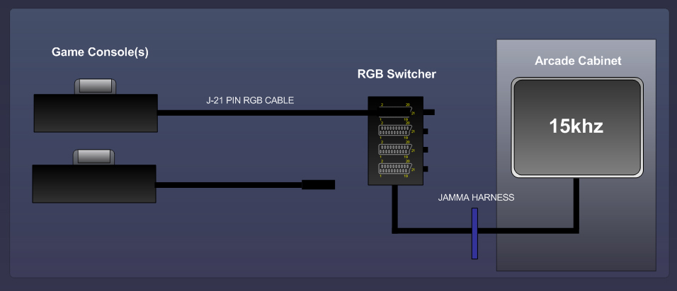
What im trying to do, is wire a 21pin switch box, into a jamma pinout (JB-2) so that way i can move it to any cabinet like a PCB board, and run 15khz consoles all day!!
so seeing the previous diagram, im wondering is there a posibble solution to have it actually work without the molex method? (thru the jamma harness) if so, how do i go about wiring this up?
any info will help thanks.
heres what i have:
J-PAC
JB-2 fingerboard
Universal AV to Arcade Monitor Adapter PCB (Ultimarc)
J21 cables
RGB modded consoles
5+ arcade cabinets
What im trying to do, is wire a 21pin switch box, into a jamma pinout (JB-2) so that way i can move it to any cabinet like a PCB board, and run 15khz consoles all day!!
so seeing the previous diagram, im wondering is there a posibble solution to have it actually work without the molex method? (thru the jamma harness) if so, how do i go about wiring this up?
any info will help thanks.
-
Dave_K.
- Posts: 4571
- Joined: Wed Jan 26, 2005 5:43 am
- Location: SF Bay Area
- Contact:
-
charlie chong

- Posts: 1529
- Joined: Fri Dec 08, 2006 12:19 pm
- Location: borders
i take it the resistors and capacitators would work for boosting the colours on my homemade jamma saturn hack as well?? i would definitely use it more if i didn't have to mess with the monitor colours everytime i swap from a normal pcb.
thanks
thanks
SLAG OFF KETSUI I SLAG OFF YOR MUM
https://soundcloud.com/vapor-teh-apparition
https://soundcloud.com/don-pachi-aka-bling-laden
https://soundcloud.com/vapor-teh-apparition
https://soundcloud.com/don-pachi-aka-bling-laden

-
monty359
- Posts: 5
- Joined: Sat Aug 25, 2012 12:49 am
Re: resistor fixed everything
hi all i am new here, plz may i request can someone re-upload the picture of the schematic by syntax_x because the link no longer works so cannot view the schematicrtw wrote:syntax_x sent me his schematic and I have uploaded it for you all to enjoy
rtw
-
rtw
- Posts: 1960
- Joined: Wed Jan 26, 2005 6:46 pm
- Location: Norway
- Contact:
Re: resistor fixed everything
Suremonty359 wrote:hi all i am new here, plz may i request can someone re-upload the picture of the schematic by syntax_x because the link no longer works so cannot view the schematic
http://gameordie.com/shmups/ultimarc_ps2_adapter.jpg
http://world-of-arcades.net
The future of ST-V rests upon our work and your work
The future of ST-V rests upon our work and your work