GBS 8200/8220 CFW Project
-
NoAffinity

- Posts: 1038
- Joined: Mon May 07, 2018 5:27 pm
- Location: Escondido, CA, USA
Re: GBS 8200/8220 CFW Project
@CatMachete do you have another clock gen? I usually buy them in a 3 pack because quality isnt always guaranteed. I'd start with confirming your wiring and no bridged connections, and if everything checks out then replace the clock gen. Lastly, make sure you're on the firmware from Rama's github. Actually you could start with the firmware before moving to hardware diagnosis/replacement.

Re: GBS 8200/8220 CFW Project
How's the quality when used as a straight transcoder to VGA or component?
Re: GBS 8200/8220 CFW Project
Which video amplifier chip does Ali's Retroscaler GBS-C is using? Does anyone know?
I am asking because there is this brazilian shop that is using THS7376IPWR claiming it has better colors and definitiion on the image.
<https://gamescare.com.br/produto/gbs-co ... mi-nativo/>
I just want to know which one has better image, the Ali's Retroscaler GBS or this brazilian GBS
Thanks everyone!
PS: this is the brazilian GBS in action <https://youtu.be/Ptb_HrzRV_A>

Re: GBS 8200/8220 CFW Project
This looks to be just a standard GBS with a custom board slapped on top for inputs. Where do you see it claiming to use a THS7376IPWR? I doubt someone produced a different GBS board. I would imagine the colors are no different than standard GBS, which seems to over emphasize blues.Solidzera wrote: ↑Tue Apr 02, 2024 12:29 am Which video amplifier chip does Ali's Retroscaler GBS-C is using? Does anyone know?
I am asking because there is this brazilian shop that is using THS7376IPWR claiming it has better colors and definitiion on the image.
<https://gamescare.com.br/produto/gbs-co ... mi-nativo/>
I just want to know which one has better image, the Ali's Retroscaler GBS or this brazilian GBS
Thanks everyone!
PS: this is the brazilian GBS in action <https://youtu.be/Ptb_HrzRV_A>
Re: GBS 8200/8220 CFW Project
The creator the man on the vídeo said it in portuguese language on the same video at 3:47. "Encoder 7376"Josh128 wrote: ↑Tue Apr 02, 2024 2:46 pmThis looks to be just a standard GBS with a custom board slapped on top for inputs. Where do you see it claiming to use a THS7376IPWR? I doubt someone produced a different GBS board. I would imagine the colors are no different than standard GBS, which seems to over emphasize blues.Solidzera wrote: ↑Tue Apr 02, 2024 12:29 am Which video amplifier chip does Ali's Retroscaler GBS-C is using? Does anyone know?
I am asking because there is this brazilian shop that is using THS7376IPWR claiming it has better colors and definitiion on the image.
<https://gamescare.com.br/produto/gbs-co ... mi-nativo/>
I just want to know which one has better image, the Ali's Retroscaler GBS or this brazilian GBS
Thanks everyone!
PS: this is the brazilian GBS in action <https://youtu.be/Ptb_HrzRV_A>
Re: GBS 8200/8220 CFW Project
Crap, I wonder if I got a bad clockgen as well, I'm not getting a picture unless I disable the external clockgen. Have only tested it on an LCD monitor with a generic VGA to HDMI adapter, though, will try my PC CRT later.
Colors look fine from over component from a PS2, but with RGBS from a Genesis, black is tinted blue, similar to this user's problem (except he was apparently getting tint with component):
viewtopic.php?p=1517685&sid=1c0a85300d3 ... 8#p1517685
Colors look fine from over component from a PS2, but with RGBS from a Genesis, black is tinted blue, similar to this user's problem (except he was apparently getting tint with component):
viewtopic.php?p=1517685&sid=1c0a85300d3 ... 8#p1517685
-
kitty666cats

- Posts: 1279
- Joined: Tue Nov 05, 2019 2:03 am
- Location: Massachusetts, USA
Re: GBS 8200/8220 CFW Project
I apparently posted this on a thread about non-scaling VGA to HDMI converters years ago:
https://www.amazon.com/Ableconn-VGA2HDM ... B00WAIX5S4
...decided to check the link and see why I was curious about it (mentioned below) and noticed a particular review on it. One that sounds great!
======
"ive tried many with my gbs-c gbs-control gbs-8200 and they all lose sync with an og xbox using component. With this one i have never had one signal drop or blackout! I would recommend!"
=====
So, looks like my intuition from years ago (looking up the Silicon Image/Lattice chipset inside led me to the link) was good! Anyone who is looking for a reliable VGA to HDMI on the output of their GBSC unit ought to give this a try. I, personally, have used an OSSC as passthrough for my GBSC... lol. I have a plasma that sucks ass over VGA, as well as not accepting 1080p (not super surprising, but like I said: looks like ass in genera w/ resolutions it DOES acceptl) but looks amazing over HDMI. But using a OSSC as a VGA to HDMI is very very excessive, unless you already have one lying around.
Sooooo, yeah - this one is a keeper! I'll link the .PDF of the chipset I linked in the old-ass thread - it literally says it accepts 240p on the input (not super relevant, but def a good sign)
First, here's a nice excerpt -
...I'd just look at that, personally. But here's the .PDF of the chipset, too...
https://www.latticesemi.com/-/media/Lat ... t_id=51619
https://www.amazon.com/Ableconn-VGA2HDM ... B00WAIX5S4
...decided to check the link and see why I was curious about it (mentioned below) and noticed a particular review on it. One that sounds great!
======
"ive tried many with my gbs-c gbs-control gbs-8200 and they all lose sync with an og xbox using component. With this one i have never had one signal drop or blackout! I would recommend!"
=====
So, looks like my intuition from years ago (looking up the Silicon Image/Lattice chipset inside led me to the link) was good! Anyone who is looking for a reliable VGA to HDMI on the output of their GBSC unit ought to give this a try. I, personally, have used an OSSC as passthrough for my GBSC... lol. I have a plasma that sucks ass over VGA, as well as not accepting 1080p (not super surprising, but like I said: looks like ass in genera w/ resolutions it DOES acceptl) but looks amazing over HDMI. But using a OSSC as a VGA to HDMI is very very excessive, unless you already have one lying around.
Sooooo, yeah - this one is a keeper! I'll link the .PDF of the chipset I linked in the old-ass thread - it literally says it accepts 240p on the input (not super relevant, but def a good sign)
First, here's a nice excerpt -
Spoiler
Excerpt:
1. General Description
The Lattice Semiconductor SiI8784 device is a high
quality, multi-format analog video decoder and
processor with an integrated dual-mode High
Definition Multimedia Interface (HDMI®)/Mobil
High-definition Link (MHL®) transmitter. A
microcontroller is integrated to reduce the system Bill
Of Materials (BOM) cost.
The SiI8784 device supports worldwide PAL, NTSC and
SECAM standards, YPbPr video signals up to 1080p @
60 Hz resolution, and RGB graphics signals from VGA
to UXGA resolutions. It also supports the SCART
interface with Fast Blanking and the D-Terminal.
This device contains a Time Base Correction (TBC)
module, a de-interlacer with a post-processor engine,
and a VBI decoder. For content protected analog
videos, HDCP will automatically be enabled on the
HDMI or MHL output.
1.1. Features
1.1.1. Analog Video Front-end
Four 10-bit Analog to Digital Convertors (ADC)
sampling up to 170 MHz
Flexible input multiplexers to support composite,
component, VGA, SCART with Fast Blanking and
D-Terminal interfaces
Supports cable plug-in detection and active video
signal detection
1.1.2. Multi-format Video Decoder
Automatic format detection
Supports NTSC, PAL, and SECAM standards of
composite input with adaptive comb filter
Supports 240p, 480i/p, 576i/p, 720p, 1080i/p
component video
Supports RGB graphics from VGA to UXGA
Supports Macrovision Type I, II, III copy protection
detection
Supports multi-standard VBI decoding: Teletext,
WSS, VPS, CC, CGMS, and V-CHIP
1.1.3. Video Processing
Time Base Correction
De-interlacer with Edge Smoothing
Automatic Phase/Position Detection
1.1.4. HDMI/MHL Transmitter
Selectable HDMI/MHL Dual-mode
Compliant with HDMI 1.4b and MHL 2.1
specifications
HDMI output up to 1080p @ 60 Hz or
UXGA @ 60 Hz resolution
MHL output up to 1080p @ 60 Hz resolution
HDCP 1.4
Audio insertion with I2
S/ SPDIF input
VBI data forwarding over HDMI/MHL
...
Figure 3.7. Transmitter Video Data Processing Path Embedded Sync Decoder
The input processor can create DE, HSYNC, and VSYNC signals using the start of active video (SAV) and end of active
video (EAV) codes within the ITU-R BT.656-format video stream.
3.4.2.1. Data Enable Generator
The transmitter includes logic to construct a DE signal from the incoming HSYNC, VSYNC, and clock. Registers are
programmed to enable the DE signal to define the size of the active display region.
3.4.2.2. Combiner
The clock, data, and sync information is combined into a complete set of signals required for TMDS encoding. From
here, the signals are manipulated by the register-selected video processing blocks.
3.4.2.3. 422 to 444 Up-sampler
Chrominance up-sampling and down-sampling increase or decrease the number of chrominance samples in each line of
video. Up-sampling doubles the number of chrominance samples in each line, converting 4:2:2 sampled video to 4:4:4
sampled video.
3.4.2.4. 444 to 422 Decimation
Decimation reduces the number of chrominance samples in each line by half, converting 4:4:4 sampled video to 4:2:2
video.
3.4.2.5. Color Space Converters (CSC)
Two color space converters (CSCs) (YCbCr to RGB and RGB to YCbCr) are available to interface to the many video
formats supplied by A/V processors and to provide full DVI backward compatibility. The CSC can be adjusted to perform
standard-definition conversions (ITU.601) or high-definition conversions (ITU.709) by setting the appropriate registers.
RGB to YCbCr
The RGBYCbCr color space converter can convert from video data RGB to standard definition or to high definition
YCbCr formats. The HDMI AVI packet defines the color space of the incoming video.
https://www.latticesemi.com/-/media/Lat ... t_id=51619
Re: GBS 8200/8220 CFW Project
First of all I wanted to thank all of the developers and supporters of this project! Such an amazing piece of tech!
It allowed me to get crisp image from my recently obtained Atari 520 STm using 2018 GBS 8200, although I'm having some issues:
1. External clock generator prevents GBS from working at all. I disconnected it and seemingly not having any issues with image upscaling.
2. I'm using an old LED Samsung TV, which has kinds of inputs I need (VGA, composite, component, RF) and a 4:3 800x600 display. With GBSC's 480p output the image is shifted to the right and I have to move and scale image to make it show in the center of the screen.
3. I stored output settings to a profile, but it does not seem to be selected/applied properly on each input blink or mode switch, so I have to manually select other preset, load it and then reload a working preset from #2.
How can modify output modes list to remove almost all 16:9 resolutions and add a proper 4:3 VGA? As I understand, I will have to modify not just the firmware sketch, but a WebUI as well. Can somebody point me to a detailed documentation/instructions of doing that?
Thank you!
Re: GBS 8200/8220 CFW Project
Greetings forum, I saw some people are concerned about the Chinese prebuilt GBS-C RetroScaler and I'd like to share my experience regards to updating the firmware.
It appears there's a few Chinese prebuilds, the few that I know of are:
GBS-C ODV
BitFunx GBS-C Pro
And the TZT/HamGeek/etc variants
I did some research, stumbled upon this Russian youtube video while I was looking how to update the Chinese default firmware, because it was two years out of date compared to the official ramapcsx2 repository, he briefly mentions that the official firmware can work on any spinoff of GBSC. In my case it did .
However, it was not without any issues. I had configured my Arduino IDE, loaded libraries, verified the sourcecode and was ready to upload via USB. Upon plugging the ESP8266 displayed the blue indicator and worked only for 5 seconds.
Next I tried powering it with the 5V2A While flashing, a potentially very stupid idea as it was not mentioned in the user manual. It could have made sense because these prebuilts have one unified PCB board, the ESP8266 is incorporated in the whole circuit, it's not just soldered
So theoretically just a USB would not have worked, it didn't power anything else not even the OLED display. I can't confirm that you need a DC input to complete the flashing.
I tried to flash at first with the official guide using the binary (bin file) and NodeMCU PyFlasher, it didn't work either.
What ended up successfully is flashing using OTA(Over the air) using the WiFi local website, then linking it with my Arduino IDE. Now I do have the latest version, I can tell because I have color correction options and the ability to delete presets, something the Chinese scaler didn't had when it shipped.
The only problem with these open source forks is that they're never maintained, they release version 1.0 and just abandon the sourcecode. Thankfully the official firmware is fully compatible as expected, though you need to compile the code yourself, and follow the steps carefully.
-
Bassa-Bassa
- Posts: 1207
- Joined: Tue Mar 12, 2019 5:18 pm
Re: GBS 8200/8220 CFW Project
Thanks for sharing. Isn't any of these prebuilt units sold with a properly updated code in 2024?Dailenth wrote: ↑Thu Apr 18, 2024 10:14 pm
The only problem with these open source forks is that they're never maintained, they release version 1.0 and just abandon the sourcecode. Thankfully the official firmware is fully compatible as expected, though you need to compile the code yourself, and follow the steps carefully.
Re: GBS 8200/8220 CFW Project
Replaced the clockgen, and that part seems to be working fine now.jd213 wrote: ↑Thu Apr 04, 2024 9:36 pm Crap, I wonder if I got a bad clockgen as well, I'm not getting a picture unless I disable the external clockgen. Have only tested it on an LCD monitor with a generic VGA to HDMI adapter, though, will try my PC CRT later.
Colors look fine from over component from a PS2, but with RGBS from a Genesis, black is tinted blue, similar to this user's problem (except he was apparently getting tint with component):
viewtopic.php?p=1517685&sid=1c0a85300d3 ... 8#p1517685
Still getting the blue tint over RGB though. All colors are showing up, but black is showing as blue for some reason.
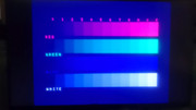
(The blue contrast isn't quite as bad as it looks in the pic, but the colors on the right of the bar definitely blend into each other a good bit)
Re: GBS 8200/8220 CFW Project
Hey ya'll! I recently finalized my GBS-C and I stripped down the VGA2HDMI and wired it directly. Ive got a problem with power supply though. Without the converter tapped into the GBS supply, all works. Once I solder the port's 5v and gnd onto the GBS, the board seems to be in a constant dim flicker and wont display. If i supply the voltage it with another supply right to the hdmi adapter, all is peachy.
What are the ideal 5v, (and 3.3v and 1.8v) points I could hook onto? Any ideas why it perhaps draws so much? I supply it with 5V 1A brick.
What are the ideal 5v, (and 3.3v and 1.8v) points I could hook onto? Any ideas why it perhaps draws so much? I supply it with 5V 1A brick.

Re: GBS 8200/8220 CFW Project
Also, am I assuming wrong when I think this should work? Wanted to have RGBS, so I used the supplied 8pin, soldered RGB to YPbPr cinches to reuse them, added a Sync cinch and hooked it up to Gamecube. Nothing, no picture. 
-
NoAffinity
- Posts: 1038
- Joined: Mon May 07, 2018 5:27 pm
- Location: Escondido, CA, USA
Re: GBS 8200/8220 CFW Project
The gbs requires about 1A alone. What's the power requirement for the hdmi adapter? Sounds like you need more power at 5v.
As far as source, assuming the hdmi adapter runs on 5v, use a multimeter to find a 5v point to tap in closest proximity to where you need to source it. Same for ground.
Not following your second question, sorry. The 8 pin connector should be fine for rgbs or rgbhv inout. If you're trying to input ypbpr via the 8 pin connector, it will not work.
Re: GBS 8200/8220 CFW Project
I am trying to display RGBs from a Pal Gamecube, I hooked up 4 new cinches to the R G B Gnd S on the leftmost part of the board and added a 100ohm resistor betwern gnd and S. Doesnt display anything.
-
NoAffinity
- Posts: 1038
- Joined: Mon May 07, 2018 5:27 pm
- Location: Escondido, CA, USA
Re: GBS 8200/8220 CFW Project
Looks like you wired from the ypbpr connector to the rgbs input, so effectively you're inputting the signal into both ypbpr and rgbs?
Also the gray wire is sync input for rgbs. The yellow wire is only used for RGBHV.
It also looks like your sync signal is ungrounded from teh RCA end, and the ground point at teh RCA end might be making contacting with L audio. I suggest cleaning up your wiring and ensuring you aren't unintentionally grounding anything.
Re: GBS 8200/8220 CFW Project
Should've made a newer photo, sorry. I ditched the idealistic idea of repurposing YPbPr cinches as inputs for RGB, naively thought once the sync signals are plugged, it would be treated as the bridged RGBs. I wired it directly to the pins on the left as mentioned. I did not ground the new cinches though, true. I'll get into it later today, thanks!
Re: GBS 8200/8220 CFW Project
As for the wiring, I'm sorry I'm coming here askin for troubleshooting with such state of the wires. It's been alot of quickshot ideas and resoldering (and the first NodeMCU was dead and I had no idea so i desoldered the whole thing, eliminating whats wrong). I will tidy up and then ask questions. Thank you for the grounding tip, I absolutely dismissed they have to be grounded. As the L R audio ones work without grounding.
Re: GBS 8200/8220 CFW Project
Are you sure the pins in the multiout header on that cable are actually connected to the RGB wires?
Re: GBS 8200/8220 CFW Project
I'm not following. The bottom (input) 8pin is the RGBs(h/v) supplied header to be used for this purpose, and the other end has my cinch connectors soldered on.
The upper (output) 8pin has R G B H V wires soldered on and it works in YPbPr mode and displays stuff thru HDMI nicely. I cant get RGBs to work.
-
NoAffinity
- Posts: 1038
- Joined: Mon May 07, 2018 5:27 pm
- Location: Escondido, CA, USA
Re: GBS 8200/8220 CFW Project
@strayan is asking about the wiring of your av cable. We can't see the whole thing - so he's asking for confirmation that the console end pins are correctly pinned out to truly provide rgbs to the rca ends. For example - does the console end pin corresponding to the red rca actually connect to the red output of the console? Does the yellow rca actually connect back to the sync output of the console?strnadik wrote: ↑Thu May 09, 2024 10:20 amI'm not following. The bottom (input) 8pin is the RGBs(h/v) supplied header to be used for this purpose, and the other end has my cinch connectors soldered on.
The upper (output) 8pin has R G B H V wires soldered on and it works in YPbPr mode and displays stuff thru HDMI nicely. I cant get RGBs to work.
Re: GBS 8200/8220 CFW Project
I see! As I purchased the cable from Ali, it didnt occur to me that it could be about the wiring of the AV cable.NoAffinity wrote: ↑Thu May 09, 2024 1:11 pm@strayan is asking about the wiring of your av cable. We can't see the whole thing - so he's asking for confirmation that the console end pins are correctly pinned out to truly provide rgbs to the rca ends. For example - does the console end pin corresponding to the red rca actually connect to the red output of the console? Does the yellow rca actually connect back to the sync output of the console?strnadik wrote: ↑Thu May 09, 2024 10:20 amI'm not following. The bottom (input) 8pin is the RGBs(h/v) supplied header to be used for this purpose, and the other end has my cinch connectors soldered on.
The upper (output) 8pin has R G B H V wires soldered on and it works in YPbPr mode and displays stuff thru HDMI nicely. I cant get RGBs to work.
https://vi.aliexpress.com/item/1005006372453616.html
-
NoAffinity
- Posts: 1038
- Joined: Mon May 07, 2018 5:27 pm
- Location: Escondido, CA, USA
Re: GBS 8200/8220 CFW Project
It's probably okay but doesn't hurt to check with a multimeter that you have continuity from end to end on the expected pins.
Also, I don't think sync on composite is an issue, or if that's how it is wired, hopefully someone can chime in and confirm sync on composite works fine with the gbs.
Also, I don't think sync on composite is an issue, or if that's how it is wired, hopefully someone can chime in and confirm sync on composite works fine with the gbs.
Re: GBS 8200/8220 CFW Project
Okay I'm stupid, I might aswell go for YPbPr GC cables (40$!!!). The PAL GC apparently doesn't do CSYNC, so I'd need the LM1881 sync stripper that is definitely not included in this 9$ cable.NoAffinity wrote: ↑Thu May 09, 2024 4:46 pm It's probably okay but doesn't hurt to check with a multimeter that you have continuity from end to end on the expected pins.
Also, I don't think sync on composite is an issue, or if that's how it is wired, hopefully someone can chime in and confirm sync on composite works fine with the gbs.
Re: GBS 8200/8220 CFW Project
Decided to print a very vanilla case for my GBS-C today, just added a hole for SCART and hopefully I'll be able to fit it all in including the sync stripper. https://imgur.com/a/OkTELN8
-
CatMachete
- Posts: 2
- Joined: Fri Jan 12, 2024 5:43 pm
Original xbox wobbly image at 720p
I’ve seen this issue reported a couple other times but I haven’t seen a solution. I’m using a 1.0 Xbox with cerbios and component cables. 480p games looks great but 720p looks all wobbly and loses sync constantly. If I use a vga to hdmi adapter the image stops wobbling but I still get a black screen every minute or so. I’ve done all the optional mods except replacing c11.
Re: GBS 8200/8220 CFW Project
I am now set on putting an LN1881 inside my GBS-C, but I was wondering. I saw someone's implementation - https://tomdalby.com/other/images/gbs8200cfwfinal.JPG
And he has the stripper on a toggle switch. Do I need it? What if I strip an already stripped sync signal? Will it get shaved off more info?
And he has the stripper on a toggle switch. Do I need it? What if I strip an already stripped sync signal? Will it get shaved off more info?
Re: GBS 8200/8220 CFW Project
Has anyone had an issue with 5V2A supply? I used to have 5V1A, and only GBS8200 and ESP drew power from it. VGA to HDMI had a separate supply. When I tapped the HDMI to GBS-C power supply, it kept dying immediately. Okay. So I switched from 5V1A to 5V2A. Seems to work nicely! Then after like a minute, I get huge interference/lines all of a sudden. Reset helps for like a minute again. https://streamable.com/3u51of
Re: GBS 8200/8220 CFW Project
Tested on some other cables, and it looks like the blue tint only shows up on certain cables I have from Retro-Access.jd213 wrote: ↑Wed May 01, 2024 11:19 pmReplaced the clockgen, and that part seems to be working fine now.jd213 wrote: ↑Thu Apr 04, 2024 9:36 pm Crap, I wonder if I got a bad clockgen as well, I'm not getting a picture unless I disable the external clockgen. Have only tested it on an LCD monitor with a generic VGA to HDMI adapter, though, will try my PC CRT later.
Colors look fine from over component from a PS2, but with RGBS from a Genesis, black is tinted blue, similar to this user's problem (except he was apparently getting tint with component):
viewtopic.php?p=1517685&sid=1c0a85300d3 ... 8#p1517685
Still getting the blue tint over RGB though. All colors are showing up, but black is showing as blue for some reason.
(The blue contrast isn't quite as bad as it looks in the pic, but the colors on the right of the bar definitely blend into each other a good bit)
Blue tint:
- Retro Access Genesis 1 custom Dsub cable (requested Csync but not sure if it actually outputs Csysnc as the cable doesn't work with my triple bypassed VA6)
- Retro Access Fortraflex Sega Genesis 2 individually shielded RGBS Dsub Cable (blue tint shows on output from both a Genesis 2 and an RGB Blaster)
no blue tint:
- Retro Access Genesis 1 custom Csync JP21 cable
- PS1 using Chipnetics "PlayBaby" Dsub adapter
- Retro Access PC-Engine custom Dsub cable
Still not sure what's causing the blue tint, maybe has something to do with the "sync buffer" that Retro Access uses.