TV RGB mod thread
Re: TV RGB mod thread
Okay I took some pictures of the board and did some crude shopping to figure out if the docs were correct about the expected pins for YUV.
Looks like i'm all set if i tap in somewhere along those traces i've marked up. I still need to trace pin 50 to see iff it's wired up to the appropriate voltage as MarkOZLAD suggested.
Re: TV RGB mod thread
You should probably rebuild the YUV circuit with all the safety components as shown in the service manual. I can see a spot for SMD capacitors.PressLeft wrote:Okay I took some pictures of the board and did some crude shopping to figure out if the docs were correct about the expected pins for YUV.
Looks like i'm all set if i tap in somewhere along those traces i've marked up. I still need to trace pin 50 to see iff it's wired up to the appropriate voltage as MarkOZLAD suggested.
Re: TV RGB mod thread
that was the plan. Unfortunately I've been unable to find the parts listed in the service manual. although i did break them down into this convention:
starts with 0 - Connector
starts with 2 - capacitor
starts with 3 - resistor
starts with 4 - Zero ohm Chip Jumper
starts with 9 - jumper
All of those spots seem to have bypass jumpers, which should mean i can stick my raw YUV signals in there without issue.
starts with 0 - Connector
starts with 2 - capacitor
starts with 3 - resistor
starts with 4 - Zero ohm Chip Jumper
starts with 9 - jumper
All of those spots seem to have bypass jumpers, which should mean i can stick my raw YUV signals in there without issue.
Re: TV RGB mod thread
Thanks KPackratt2k, and thanks Makozlad, a succesfull mod done, i even took it apart and installed it into a champios pub countertop cabinet. fits spot on. Now to install software. Thanks alot guys, i still need to find out.KPackratt2k wrote:Even if you're using SCART, I would still recommend using a switch for blanking because not all cables handle blanking. If you insist on blanking via SCART, you can try adding a diode on the blanking wire.
If you have more than one of these TVs and wouldn't mind parting one of them out for me, let me know. I have a Mickey TV that suffered from a vertical IC failure and I wasn't able to fix its chassis. I would love to get mine working again.
Re: TV RGB mod thread
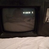
More than likely, this TV isn't compatible with the mod. Some firmware versions aren't, unfortunately. I've had the same results with other Philips/Magnavox models. You should get "CVI" in the top left corner when changing inputs.PressLeft wrote:156 didn’t get me SVHS or CVI, but it did get me “X 1” as a channel in addition to me “FRONT” AV option (i believe this is AV3).
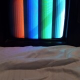
Some other values enabling AV and AV2 (202) did get me a really bizarre moving black and white triangle pattern. Seen here: https://i.imgur.com/ln4k6cl
This pattern gets a little more erratic when input is provided to the front composite, which makes me think this might be S-video? It could also be the sync signal for RGB? Idk, but it’s definitely some portion of a signal for another type of input that hardware is missing for.
Actually, after fiddling with it a bit, I also saw “X AV” after switching back from 202 to 156. I suspect “X” is actually just a signifier that the currently selected input has been disabled. If you CH+/- away from it you can’t return to it unless you change the options to enable it again.
Edit:
I decided to try enabling everything but hotel and PIP modes by entering 252 for OP5. This got me the following results:
- AV1: black and white triangle pattern linked above; this is affected somehow by the input on the front
- AV2: duplicates Front input
- Front: the composite input on the front as expected
- RF
I suspect that this means:
- AV1 is component or RGB; my reasoning is that the image changes from receiving a signal on front input, which would indicate that’s some portion of the signal, like sync
- AV2 is s-video; my reasoning is that it duplicates the front signal, which would appear identical to composite if chroma & luma were being combined
- Front is AV3 as documented.
But, it couldn't hurt to try. There should be an empty set of resistor pads from the YUV switch pin that you can populate to get the blanking voltage. I'd try adding a Y signal to the input pin first (with 75 ohm termination and coupling cap) and see if you can get a B&W picture through any of the inputs. If so, the rest of the mod might work.
Re: TV RGB mod thread
Completed the RGB Mux Mod on the Sanyo DS31520.
Just realized the picture on this is super dark, and the OSD Menu doesn't affect the picture I assume I need to use the comb filter for the OSD to work properly? Does anyone know a better sync location? The sync is all messed up going directly to luma or composite, but wiring directly beyond the comb filter is too dark Here is the manual https://www.manualslib.com/manual/90907 ... 31520.html
Right now i have sync wired to R8065, just above the IC101
EDIT: In the service manual, the setting "OSD Contrast" can be raised, and it is a little brighter but certainly not ideal, as the contrast is too high. Does this mean that the RGB signals are seen as OSD and not the Video Input?
Re: TV RGB mod thread
Yes, a lot of these TVs control OSD levels separately from the rest of the video. Some don't let you adjust RGB brightness or contrast at all!
If you're having trouble getting good black levels, try increasing the RGB cutoffs values. That usually does the trick. You'll have to reduce sub brightness on composite to match.
Re: TV RGB mod thread
Yeah those LA768XX jungles suck dogs balls.
Does "Sub Bias" in the Service Menu have any effect?
___________________________________________________
MarkOZLAD
OSD/External RGB Mux Diagram
OSD/External RGB Mux Resistor Value Table 0.7Vp-p : 0.5Vp-p
"Imagine toggle switch OSD modding a TV in 2019" - maxtherabbit
MarkOZLAD
OSD/External RGB Mux Diagram
OSD/External RGB Mux Resistor Value Table 0.7Vp-p : 0.5Vp-p
"Imagine toggle switch OSD modding a TV in 2019" - maxtherabbit
Re: TV RGB mod thread
the other thing I think might be in play on the LA768XX jungles is this setting in the registers.
An I2C hack may be able to be used to turn this off and enable the clamping.
___________________________________________________
MarkOZLAD
OSD/External RGB Mux Diagram
OSD/External RGB Mux Resistor Value Table 0.7Vp-p : 0.5Vp-p
"Imagine toggle switch OSD modding a TV in 2019" - maxtherabbit
MarkOZLAD
OSD/External RGB Mux Diagram
OSD/External RGB Mux Resistor Value Table 0.7Vp-p : 0.5Vp-p
"Imagine toggle switch OSD modding a TV in 2019" - maxtherabbit
Re: TV RGB mod thread
matt wrote:If you're having trouble getting good black levels, try increasing the RGB cutoffs values. That usually does the trick. You'll have to reduce sub brightness on composite to match.
Thank you guys so much! Glad I didn't open it up again The Sub Bias setting worked. At first I thought it wasn't working but I just had to crank it really high, more than double the initial setting. The LA768XX jungle has finally stopped it's suckling!MarkOZLAD wrote:Yeah those LA768XX jungles suck dogs balls.
Does "Sub Bias" in the Service Menu have any effect?
Re: TV RGB mod thread
Full writeup of Sanyo DS31520 Mux Mod. Note that although it is technically a mux, the picture menu settings will not work. Should be a similar mod for other sets with the infamous LA76834NMP or variants of it. Also, i would recommend turning down OSD Contrast(setting 22, OSD) from 2 to 1 to make up for the Sub Bias change. Looks great this way.
Re: TV RGB mod thread
The fact that the picture controls do nothing has no bearing on whether it’s a Mux.
If you look at block diagrams of these jungles you’ll see that the external RGB bypasses all those controls. It’s pretty much just straight to an amplification section.
___________________________________________________
MarkOZLAD
OSD/External RGB Mux Diagram
OSD/External RGB Mux Resistor Value Table 0.7Vp-p : 0.5Vp-p
"Imagine toggle switch OSD modding a TV in 2019" - maxtherabbit
MarkOZLAD
OSD/External RGB Mux Diagram
OSD/External RGB Mux Resistor Value Table 0.7Vp-p : 0.5Vp-p
"Imagine toggle switch OSD modding a TV in 2019" - maxtherabbit
Re: TV RGB mod thread
And its dark because there is no DC offset/bias control.
I bet the picture looks like ass, would be missing heaps of detail in the darker areas.
Re: TV RGB mod thread
Ah, i didnt realize that. I assumed they normally work, since at least the brightness works on my first mod, the Panasonic WV-CK2020A.MarkOZLAD wrote:The fact that the picture controls do nothing has no bearing on whether it’s a Mux.
It definitely did look like ass before Mark's fix. I think it looks fantastic now I was able to lower contrast via "OSD Contrast," so the lighter parts of the image didn't get crushed.Syntax wrote:I bet the picture looks like ass, would be missing heaps of detail in the darker areas.
Here's a pic comparing it to one of my PVM's(750tvl Olympus). The image of the PVM is out of focus but you get the idea. The Sanyo is a bit too on the cool side, as you'll notice immediately. Scanlines are thicc though
https://i.imgur.com/tlBohJh.jpeg
If you look below the monsters, you can see that the dark dirt details are proper. Pic is out of focus again, sorry. Looks much better in person. Sigh.
https://i.imgur.com/0KnPoJG.jpg
-
- Posts: 4
- Joined: Mon Jul 11, 2022 10:12 am
Re: TV RGB mod thread
Hi All , I'm pretty new to RGB modding (this will be my first attempt) so wouldn't mind some advice if Í'm on the right track or not with my set.
I have a Sony KV-PG21P10 with the BG2T chassis , with a TDA8843 jungle IC. The service manual is here https://data2.manualslib.com/pdf6/123/1 ... 1a1cf9f9c5 Initially I thought I would need to do a Mux type mod but then after a bit of research it looks like I can just inject RGB into the unused teletext header on CN001 which should be a bit easier.
I would terminate the RGB inputs prior to CN001 on the RCA plugs looks tidy , using 75 ohm and run the grounds back to CN001 ground pin.
People suggest taking 5V from the jumper wire JW033 which is connected to the +5V regulator IC002 and making a voltage divider to bring the blanking voltage down to 2.3V using 2x 75 ohm resistors as it looks like 3v is max for blanking on the jungle, and feeding this into CN001 blanking pin.
The bit that I'm least sure about is removing R330, R331, R332 which are grounding the RBG lines from CN001 on the way to the jungle, from the service manual it says these are 0 ohm if reading it correctly , do these need removing ?
Anything missing from the above or to watchout for ?
Any advice appreciated.
Re: TV RGB mod thread
Hey guys, I'm trying to do my first RGB mod but having some trouble finding the RGB-in pins on jungle chip.
Can you guys give me some help?
My TV is a LG RP-14CB25A and thats the schematics (page 19) > https://www.electronica-pt.com/esquema/ ... no_html,1/
Can you guys give me some help?
My TV is a LG RP-14CB25A and thats the schematics (page 19) > https://www.electronica-pt.com/esquema/ ... no_html,1/
-
- Posts: 223
- Joined: Sun Apr 04, 2021 11:02 pm
- Location: Seattle, WA, USA
Re: TV RGB mod thread
I've successfully modded a Sony KV-27XBR45 for a friend of mine. I figured this TV could be modded going by posts from another member and the schematics in the service manual, so I gave it a shot and succeeded the first time. I really wanted to make sure I did it correctly with one shot because the way this TV is set up internally makes it difficult to put back together once taken apart since there are so many cables that connect to different places.
https://imgur.com/a/qz4DO1A
Modding Schematic:
If you plan on doing this, make sure to turn off Velocity Modulation (VM) in the Video Settings menu, otherwise there will be ghosting on your image.
https://imgur.com/a/qz4DO1A
Modding Schematic:
Spoiler
Re: TV RGB mod thread
You can leave and use the 0.01uF SMD caps.KPackratt2k wrote:I've successfully modded a Sony KV-27XBR45 for a friend of mine. I figured this TV could be modded going by posts from another member and the schematics in the service manual, so I gave it a shot and succeeded the first time. I really wanted to make sure I did it correctly with one shot because the way this TV is set up internally makes it difficult to put back together once taken apart since there are so many cables that connect to different places.
https://imgur.com/a/qz4DO1A
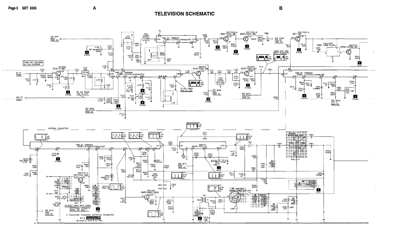
Modding Schematic:If you plan on doing this, make sure to turn off Velocity Modulation (VM) in the Video Settings menu, otherwise there will be ghosting on your image.Spoiler
I would run a jumper between the top and bottom s-video pins to permanently enable S-video. Do you really care about losing 1 composite input? Then you could wire scart blanking. I can't find the datasheet for your jungle chip but since it has separate Ys and Ym inputs, it likely only needs 1v to enable blanking. If so you can replace R366 470 ohm with a 390+75 ohm resistors in series, micon and ground side respectfully, and connect SCART-16 between the 2 resistors. Then you'll have SCART switching and no need for the switch.
With that said, you could try component modding the TV. You could use a DPDT ON-OFF-ON switch to select between SCART, S-video and component inputs. 1 Pole selects sync, the other pole selects blanking. You could remove the components on video OUTPUT and reuse those RCAs for component input: Yellow -> Y, White -> Pb, Red -> Pr.
You can also wire the signal grounds to S-Video pin 1 or 2.
-
- Posts: 223
- Joined: Sun Apr 04, 2021 11:02 pm
- Location: Seattle, WA, USA
Re: TV RGB mod thread
The SMD capacitors make the connection from the External RGB pins to the Closed Captioning Decoder, I didn't want to take a chance with that, plus with how small they were it would be extremely difficult, if not impossible, to run wires from them.Ryeno wrote:You can leave and use the 0.01uF SMD caps.
I would run a jumper between the top and bottom s-video pins to permanently enable S-video. Do you really care about losing 1 composite input? Then you could wire scart blanking. I can't find the datasheet for your jungle chip but since it has separate Ys and Ym inputs, it likely only needs 1v to enable blanking. If so you can replace R366 470 ohm with a 390+75 ohm resistors in series, micon and ground side respectfully, and connect SCART-16 between the 2 resistors. Then you'll have SCART switching and no need for the switch.
With that said, you could try component modding the TV. You could use a DPDT ON-OFF-ON switch to select between SCART, S-video and component inputs. 1 Pole selects sync, the other pole selects blanking. You could remove the components on video OUTPUT and reuse those RCAs for component input: Yellow -> Y, White -> Pb, Red -> Pr.
You can also wire the signal grounds to S-Video pin 1 or 2.
I didn't ask the owner if he wanted to keep using the Video 1 input as Composite, but since there are two additional inputs on this set, it seems unlikely, but I don't know for sure. Not all SCART cables handle blanking from what I've heard, so it seemed like a safer bet to use a switch.
With how packed everything was inside the set, I didn't think Component modding it would've been a good idea since I would have to run another set of wires through the small space between the UA board and the two boards that connect on top of it. I already had to deal with running two sets of four wires through that cavity, so I didn't want to take the risk with three sets of four. Also, I don't know how well this set would handle running without its PIP board since it uses the YUV lines on the jungle chip.
Re: TV RGB mod thread
That's because there aren't any.gabnattz wrote:Hey guys, I'm trying to do my first RGB mod but having some trouble finding the RGB-in pins on jungle chip.
Can you guys give me some help?
My TV is a LG RP-14CB25A and thats the schematics (page 19) > https://www.electronica-pt.com/esquema/ ... no_html,1/
___________________________________________________
MarkOZLAD
OSD/External RGB Mux Diagram
OSD/External RGB Mux Resistor Value Table 0.7Vp-p : 0.5Vp-p
"Imagine toggle switch OSD modding a TV in 2019" - maxtherabbit
MarkOZLAD
OSD/External RGB Mux Diagram
OSD/External RGB Mux Resistor Value Table 0.7Vp-p : 0.5Vp-p
"Imagine toggle switch OSD modding a TV in 2019" - maxtherabbit
Re: TV RGB mod thread
Orthello77 wrote:Hi All , I'm pretty new to RGB modding (this will be my first attempt) so wouldn't mind some advice if Í'm on the right track or not with my set.
I have a Sony KV-PG21P10 with the BG2T chassis , with a TDA8843 jungle IC. The service manual is here https://data2.manualslib.com/pdf6/123/1 ... 1a1cf9f9c5 Initially I thought I would need to do a Mux type mod but then after a bit of research it looks like I can just inject RGB into the unused teletext header on CN001 which should be a bit easier.
I would terminate the RGB inputs prior to CN001 on the RCA plugs looks tidy , using 75 ohm and run the grounds back to CN001 ground pin.
People suggest taking 5V from the jumper wire JW033 which is connected to the +5V regulator IC002 and making a voltage divider to bring the blanking voltage down to 2.3V using 2x 75 ohm resistors as it looks like 3v is max for blanking on the jungle, and feeding this into CN001 blanking pin.
The bit that I'm least sure about is removing R330, R331, R332 which are grounding the RBG lines from CN001 on the way to the jungle, from the service manual it says these are 0 ohm if reading it correctly , do these need removing ?
Anything missing from the above or to watchout for ?
Any advice appreciated.
It's an unused RGB input method. No need for mux, the OSD is mixed after jungle. R330, 331 and 332 are jumpers to ground that need to be removed. You'll probably find that the values installed on the set aren't 0.
For blanking measure the resistance to ground from the Blanking pin at CN001. You'll find there is already a resistor to ground, just need to calculate an inline resistor for your 5V line using the existing resistance. Want voltage to be between 1V and 3V.
___________________________________________________
MarkOZLAD
OSD/External RGB Mux Diagram
OSD/External RGB Mux Resistor Value Table 0.7Vp-p : 0.5Vp-p
"Imagine toggle switch OSD modding a TV in 2019" - maxtherabbit
MarkOZLAD
OSD/External RGB Mux Diagram
OSD/External RGB Mux Resistor Value Table 0.7Vp-p : 0.5Vp-p
"Imagine toggle switch OSD modding a TV in 2019" - maxtherabbit
Re: TV RGB mod thread
There is any possibility to mod the tv injecting the RGB directly to the neckboard pins?MarkOZLAD wrote:That's because there aren't any.gabnattz wrote:Hey guys, I'm trying to do my first RGB mod but having some trouble finding the RGB-in pins on jungle chip.
Can you guys give me some help?
My TV is a LG RP-14CB25A and thats the schematics (page 19) > https://www.electronica-pt.com/esquema/ ... no_html,1/
Re: TV RGB mod thread
On the curved 90s Trinitons, I remove the CC and PIP boards and run the wires to their spots. They aren't required and this eliminates the possibility of any interference from them.KPackratt2k wrote:The SMD capacitors make the connection from the External RGB pins to the Closed Captioning Decoder, I didn't want to take a chance with that, plus with how small they were it would be extremely difficult, if not impossible, to run wires from them.Ryeno wrote:You can leave and use the 0.01uF SMD caps.
I would run a jumper between the top and bottom s-video pins to permanently enable S-video. Do you really care about losing 1 composite input? Then you could wire scart blanking. I can't find the datasheet for your jungle chip but since it has separate Ys and Ym inputs, it likely only needs 1v to enable blanking. If so you can replace R366 470 ohm with a 390+75 ohm resistors in series, micon and ground side respectfully, and connect SCART-16 between the 2 resistors. Then you'll have SCART switching and no need for the switch.
With that said, you could try component modding the TV. You could use a DPDT ON-OFF-ON switch to select between SCART, S-video and component inputs. 1 Pole selects sync, the other pole selects blanking. You could remove the components on video OUTPUT and reuse those RCAs for component input: Yellow -> Y, White -> Pb, Red -> Pr.
You can also wire the signal grounds to S-Video pin 1 or 2.
I didn't ask the owner if he wanted to keep using the Video 1 input as Composite, but since there are two additional inputs on this set, it seems unlikely, but I don't know for sure. Not all SCART cables handle blanking from what I've heard, so it seemed like a safer bet to use a switch.
With how packed everything was inside the set, I didn't think Component modding it would've been a good idea since I would have to run another set of wires through the small space between the UA board and the two boards that connect on top of it. I already had to deal with running two sets of four wires through that cavity, so I didn't want to take the risk with three sets of four. Also, I don't know how well this set would handle running without its PIP board since it uses the YUV lines on the jungle chip.
All the common SCART cables handle switching. Having automatic switching is one of the main benefits of install the SCART connector.
-
- Posts: 4
- Joined: Mon Jul 11, 2022 10:12 am
Re: TV RGB mod thread
Thanks a lot for the info re this ! I did think it was odd the service manual said 0 ohm. Thanks again and hopefully report back with a successfull mod soon.MarkOZLAD wrote:Orthello77 wrote:Hi All , I'm pretty new to RGB modding (this will be my first attempt) so wouldn't mind some advice if Í'm on the right track or not with my set.
I have a Sony KV-PG21P10 with the BG2T chassis , with a TDA8843 jungle IC. The service manual is here https://data2.manualslib.com/pdf6/123/1 ... 1a1cf9f9c5 Initially I thought I would need to do a Mux type mod but then after a bit of research it looks like I can just inject RGB into the unused teletext header on CN001 which should be a bit easier.
I would terminate the RGB inputs prior to CN001 on the RCA plugs looks tidy , using 75 ohm and run the grounds back to CN001 ground pin.
People suggest taking 5V from the jumper wire JW033 which is connected to the +5V regulator IC002 and making a voltage divider to bring the blanking voltage down to 2.3V using 2x 75 ohm resistors as it looks like 3v is max for blanking on the jungle, and feeding this into CN001 blanking pin.
The bit that I'm least sure about is removing R330, R331, R332 which are grounding the RBG lines from CN001 on the way to the jungle, from the service manual it says these are 0 ohm if reading it correctly , do these need removing ?
Anything missing from the above or to watchout for ?
Any advice appreciated.
It's an unused RGB input method. No need for mux, the OSD is mixed after jungle. R330, 331 and 332 are jumpers to ground that need to be removed. You'll probably find that the values installed on the set aren't 0.
For blanking measure the resistance to ground from the Blanking pin at CN001. You'll find there is already a resistor to ground, just need to calculate an inline resistor for your 5V line using the existing resistance. Want voltage to be between 1V and 3V.
Re: TV RGB mod thread
It is possible but it’s not something I’ve done.gabnattz wrote:There is any possibility to mod the tv injecting the RGB directly to the neckboard pins?MarkOZLAD wrote:That's because there aren't any.gabnattz wrote:Hey guys, I'm trying to do my first RGB mod but having some trouble finding the RGB-in pins on jungle chip.
Can you guys give me some help?
My TV is a LG RP-14CB25A and thats the schematics (page 19) > https://www.electronica-pt.com/esquema/ ... no_html,1/
There’s a bunch of Brazilian fellas who are champs at doing that.
___________________________________________________
MarkOZLAD
OSD/External RGB Mux Diagram
OSD/External RGB Mux Resistor Value Table 0.7Vp-p : 0.5Vp-p
"Imagine toggle switch OSD modding a TV in 2019" - maxtherabbit
MarkOZLAD
OSD/External RGB Mux Diagram
OSD/External RGB Mux Resistor Value Table 0.7Vp-p : 0.5Vp-p
"Imagine toggle switch OSD modding a TV in 2019" - maxtherabbit
Re: TV RGB mod thread
I recently modded a Trinitron and seem to be having an intermittent problem with ghosting/green tint. The problem seems to occur randomly as the TV will work fine through RGB most of the time.
The tint/ghosting does not manifest if I switch svideo or composite , and if i use those inputs for a while and switch back to RGB the picture will be ok again.
It almost seems like the jungle is having a program error or something. I've checked & redone my soldering and all seems fine. Has anyone else had this issue?
https://imgur.com/a/HxjQ5vG
Re: TV RGB mod thread
Post the model number and how you did the mod.retrozar wrote:I recently modded a Trinitron and seem to be having an intermittent problem with ghosting/green tint. The problem seems to occur randomly as the TV will work fine through RGB most of the time.
The tint/ghosting does not manifest if I switch svideo or composite , and if i use those inputs for a while and switch back to RGB the picture will be ok again.
It almost seems like the jungle is having a program error or something. I've checked & redone my soldering and all seems fine. Has anyone else had this issue?
https://imgur.com/a/HxjQ5vG
Re: TV RGB mod thread
So over the weekend I purchased 2 CRT's, A Sony Trinitron PVM 14N5U and a Toshiba 14AF43. I was curious which one is worth keeping as I only need one to play on, and I wasnt sure if its worth going through the trouble of modding the PVM to do RGB or if I should just keep the Toshiba since it has S-video/component/composite anyway. Just a heads up though, Im new to the whole CRT/PVM scene so im not confident enough to take the PVM apart and try to mod it. Any tips, helpful advice are appreciated, Thanks in advanced.
Re: TV RGB mod thread
14N5U is quite nice. It uses the same tube and yoke as the 14M2U so the scanlines, convergence and geometry are just as good. The rest of the circuitry isn't as good so the image has quite a bit of blooming, worse focus and the service manual says to calibrate it to 150cd/m^2. If you go above, the image starts distorting.DefaulT wrote:So over the weekend I purchased 2 CRT's, A Sony Trinitron PVM 14N5U and a Toshiba 14AF43. I was curious which one is worth keeping as I only need one to play on, and I wasnt sure if its worth going through the trouble of modding the PVM to do RGB or if I should just keep the Toshiba since it has S-video/component/composite anyway. Just a heads up though, Im new to the whole CRT/PVM scene so im not confident enough to take the PVM apart and try to mod it. Any tips, helpful advice are appreciated, Thanks in advanced.
Modding the 14N5U for RGB is relatively easy. The biggest challenge is desoldering the metal plate from the PCB. You need a decent soldering iron or you need to be lucky and have little solder between the PCB and the metal tabs. The 2nd biggest challenge would be crimping wires to create RGB cable between the input board and main board. The 3rd challenge is cutting the front panel add the RGB switch. The rest of the mod is pretty straight forward.
You could follow this guide for a quick and dirty hack. https://github.com/phrederick/Sony-SSM- ... dification However, I would recommend rebuilding the buffer circuits as shown in the parts diagram. I have extra factory transistors and diodes so if you want, I could send you some, or you could find equivalent parts. I also have extra buttons for the face.
After you RGB mod it, I would recommend calibrating the white balance. Else, copy over the white balance settings (C/O X and DRV X) from CVBS to RGB.
-
- Posts: 1
- Joined: Sun Jul 24, 2022 12:04 am
Re: TV RGB mod thread
Long time lurker, first time poster.
I'm working on a Sony Color Watchman FDT-5BX5. I'm looking to add some other video input besides the included composite signal. I've attempted to find/buy the schematic for this TV and attempted to find the datasheet for the jungle IC (Toshiba TA8864AN). I have not found much relevant information.
I have a few diagrams and a general IC Function Page from a service manual from a TV that uses the same Jungle.
To my understanding a RGB mod is mostly out of the picture without a major circuitry change.
I see YUV output listed on the page for IC Functions but following the circuits I do not see any hope of a mod for component, or s video. Hopefully someone a little more knowledgeable than me can confirm if there is hope past composite on this little guy or if they have a lead as to where to find a data sheet for this IC.