TV RGB mod thread

The place for all discussion on gaming hardware
shikikanzero
Posts: 16
Joined: Sat Jan 02, 2021 9:33 am

Re: TV RGB mod thread

Post by shikikanzero »

matt wrote:Sorry I missed this when you posted it. Always nice to see other people here from Hawaii. What island are you on? I've done a number of RGB mods and am happy to help if you're on Oahu.

Here's the data sheet for your jungle chip if you didn't find it already:
https://datasheetspdf.com/pdf/610984/Re ... 61251AFP/1

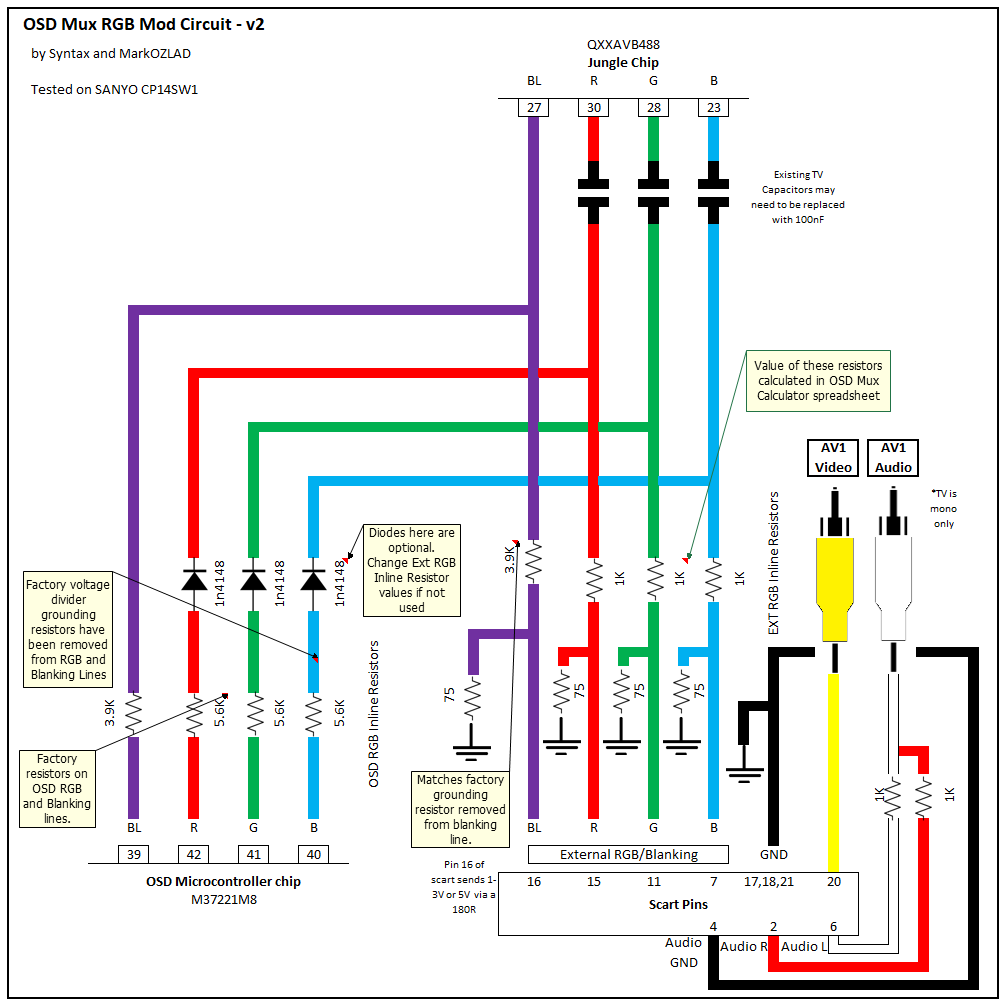
It's very similar to the jungle chips used by the Toshiba AF series, which usually do well with RGB mods and have been documented pretty well. The chip can be set to take digital or analog RGB, but fortunately the schematic looks like a typical circuit for analog inputs so I think it would work. The usual OSD mix method should work fine. Have you looked up MarkOZLad's posts on the subject?
vol.2 wrote: What I see on the schematic is Zero Volts DC coming out of the OSD output on the character generation chip and roughly 2.3VDC on the OSD inputs on the Jungle IC. I also do not see any DC restoration circuit in between the two lines, or a level shift chip. I see 2.3VDC coming out of the Jungle IC RGB outputs that are going to the neck board. That might suggest that the OSD is directly coupled to the RGB output and the RGB input voltage level simply reflects the output voltage level (because they are just joined at that point) and the caps and resistors between the Char Gen IC and the Jungle IC are there to just block the DC offset in the direction of the character IC.
I don't think this is out of the ordinary. According to its data sheet, the jungle chip expects 0.7pp RGB in analog mode and 1vpp for digital. 2.3v on the input is pretty normal for OSD signals, and I think the 0v on the Micon outputs is an irregularity with the schematic.
Nah, thank you for doing the community a service, its not like you have to reply to everyone asking for help, so really appreciate it.

I actually am on Oahu. I have read through quite a bit of this thread, and while I do get the circuit that needs to be built, I have no idea how you guys determine when and where you need resistors or capacitors, and at what values, and what they even do for the circuit as far as its relation to the signal. I have seen that spec sheet for the Renesas chip before, and other than the pinouts, I wasn't able to absorb much from it.

Though with the information you gave me, I now think I figured out how to use MarkOZLad's resistor chart. Looks like ill need to

Remove the 330ohm resistors to ground for RGB
Add 180ohm resistors in series after the 330ohm resistors on the RGB lines
add 75ohm resistors to ground before the 180ohm resistors

Hoping I'm right here. Would I be getting sync on composite? And as for the blanking voltage, how much and would it be before or after the 560 ohm resistor? I've reviewed some Toshiba AF series RGB mods (from The SegaHolic and Analog Thinker, specifically) but not sure if I should be using the same reference voltages they used on their Toshiba sets.
shikikanzero
Posts: 16
Joined: Sat Jan 02, 2021 9:33 am

Re: TV RGB mod thread

Post by shikikanzero »

matt wrote:
shikikanzero wrote:There is a space for a header on the board between the MICOM and jungle chip labeled RGB, and looking at another model (although with slightly different chipsets) there does seem to be a use for this jumper.
I took another look at your TV's service manual. It looks like this header is just what you need - it connects to all 3 of the OSD RGB lines and the blanking pin (pins 1-4 are B, G, R, and blanking respectively). If you populate this header you'll have access to all 4 of the signals you need from the top of the PCB, which simplifies things a lot.

If you haven't seen it already, the OSD mixing circuit is pretty easy to follow:
Spoiler
Image
For your TV, you'll have to remove resistors R1068, R1070, and R1075. The RGB lines will each need a 75 ohm terminating resistor to ground, and a 180 ohm inline resistor before they connect to the header (you might have to try a few different values for this one to get the OSD brightness right). For my mods I usually just put these on the RGB input connector and run the wires from there. For blanking, you'll have to find a +5v source on the PCB and run it through a switch to pin 4 of the header (I usually add a 1k resistor for safety). I couldn't find a voltage listed for the blanking pin on your jungle chip's data sheet, but +5v has worked fine for other Renesas chips so it should be OK.

Awesome, I think you posted this as I was typing up my earlier response. Yeah, I did tone out the header and did find that it was inline with the circuit from the OSD to Jungle chip, but that's about as far as i got. Ill try this out, thanks!

...also, after watching a couple of The SegaHolics videos, I can hear he has that local accent we all have. He's also from Hawaii isn't he
User avatar
vol.2
Posts: 2462
Joined: Mon Oct 31, 2016 3:13 pm
Location: bmore

Re: TV RGB mod thread

Post by vol.2 »

matt wrote: I don't think this is out of the ordinary. According to its data sheet, the jungle chip expects 0.7pp RGB in analog mode and 1vpp for digital. 2.3v on the input is pretty normal for OSD signals, and I think the 0v on the Micon outputs is an irreguarity with the schematic.
I wasn't able to find the datasheet for that chip, so I couldn't tell what it was capable of processing (the datasheet did not have the "A" as in M61251"A"FP, I was searching for M61251FP) . I still think the zero volts is correct though; I managed to find another TV schematic using that Jungle IC in a different configuration, and it also had zero volts output on the OSD. It's just the DC voltage offset, not the pk2pk.
toxictigga
Posts: 10
Joined: Sat Mar 06, 2021 5:22 am

Re: TV RGB mod thread

Post by toxictigga »

Is there a way to RGB mod this TV? It has a single chip, however someone on reddit pointed out there is a possible path to intercepting and sending the RGB signals directly to the neck board.

TV Model: Toshiba 13" CRT 13A24

I have one spare TV of the same kind. Therefore definitely up for the experiment.

Please help and let me know if any additional information is needed.
Last edited by toxictigga on Mon Jan 24, 2022 6:10 am, edited 2 times in total.
User avatar
matt
Posts: 580
Joined: Mon May 09, 2005 5:46 am
Location: Honolulu, Hawaii

Re: TV RGB mod thread

Post by matt »

shikikanzero wrote: ...also, after watching a couple of The SegaHolics videos, I can hear he has that local accent we all have. He's also from Hawaii isn't he
Yes, he's from Waipahu. There are a few CRT enthusiasts here but it seems like less than on the mainland.

Sync should go to the Y signal from either the S-Video or component port. These won't have as much of a horizontal offset as the composite input. I've found that some TVs do better with composite video for sync than pure Csync (and of course, if you have a console with TTL level sync it should be attenuated to 75 ohm levels).

Generally, my first step is to make sure the blanking works, then wire in the RGB lines to figure out the resistor levels before finalizing the mod.
vol.2 wrote:I wasn't able to find the datasheet for that chip, so I couldn't tell what it was capable of processing (the datasheet did not have the "A" as in M61251"A"FP, I was searching for M61251FP) . I still think the zero volts is correct though; I managed to find another TV schematic using that Jungle IC in a different configuration, and it also had zero volts output on the OSD. It's just the DC voltage offset, not the pk2pk.
Hmm, you're right - I missed the AFP vs FP label.

I checked a couple of Toshiba/Orion schematics for models that I have, and they all have the same quirk in the schematic (0v at the micon, 2.9 volts at the jungle in this case). This includes the 14AF43, which I've done an RGB mod on that worked. I don't think this will be a problem.
User avatar
vol.2
Posts: 2462
Joined: Mon Oct 31, 2016 3:13 pm
Location: bmore

Re: TV RGB mod thread

Post by vol.2 »

matt wrote:
Hmm, you're right - I missed the AFP vs FP label.
My guess is that they have the same pinout anyway. I have used that trick to find other elusive datasheets, mostly with correct results. Also it seems to basically match up to the schematic, so I think it's right.
I checked a couple of Toshiba/Orion schematics for models that I have, and they all have the same quirk in the schematic (0v at the micon, 2.9 volts at the jungle in this case). This includes the 14AF43, which I've done an RGB mod on that worked. I don't think this will be a problem.
[/quote]

Yeah, I agree. It's probably fine. I just found it confusing that it says zero volts on the output and 2.3V on the input. I think either the RGB output is directly coupled to the OSD input, or there is some DC restoration going inside the IC that is directly coupled to the input pins. Just different from other TVs I've worked on.
Galaxy_Rose
Posts: 4
Joined: Mon May 02, 2016 3:34 am

Re: TV RGB mod thread

Post by Galaxy_Rose »

I found a Sanyo AVM-2555 on the side of the road and after getting the HV to work again, set about RGB modding it. I found out it uses the LA7673 (cousin to the LA7674) which combines blue and blanking. This in-of itself was not difficult to get around; however, when I injected my external RGB signal (Sega Genesis), I just got a blank screen. After putting a THS7314 in the chain I did manage to get an image, just a patchy image that was missing some darker shaded colors.
Spoiler
Image
I followed this up by putting another THS7314 in the chain and got a significantly brighter image though this was still missing a few shades.
Spoiler
Image
I noticed that the circuit for LA7673/LA7674 doesn't use any in-line 100nf capacitors by default and any attempt to add them simply gives no image. From reading up on other's experiences with these lack of capacitors it seems like this creates an issue for inputting 0.7vpp signals. Any attempts to 75ohm terminate the signals also result in no image. I'm at a bit of a loss here since it seems like an amplification issue though I can't say for sure.
Spoiler
Image
Spoiler
Image
If I left anything out please let me know and I'll do my best to fill in any gaps.
User avatar
vol.2
Posts: 2462
Joined: Mon Oct 31, 2016 3:13 pm
Location: bmore

Re: TV RGB mod thread

Post by vol.2 »

Galaxy_Rose wrote: If I left anything out please let me know and I'll do my best to fill in any gaps.
According to the datasheet of the LA7673, the OSD input is 2-6VDC. If you look at page 4 of the datasheet: https://pdf1.alldatasheet.com/datasheet ... A7674.html

It says that the minimum acceptable input threshold voltage is 1.9VDC. I don't think it has a clamp on the input (for the OSD, the video input has a clamp).

The datasheet goes on to have different expected output voltages for OSD based on input level (3V,4V,5V). So, I guess it's expecting the OSD signal to be between 3-5VDC basically.

I think the main issue you are having is one of input voltage level. I think I've read about people doing TTL conversion elsewhere here, that might do the trick. You'll have to be careful to bring it up to the correct voltage as stated in the schematic though. If you output as 6V, and it's expecting 3V, you could damage something down the line.

Sorry I can't be more help, but I can at least see why what you're doing isn't working. That makes sense.
Galaxy_Rose
Posts: 4
Joined: Mon May 02, 2016 3:34 am

Re: TV RGB mod thread

Post by Galaxy_Rose »

vol.2 wrote: According to the datasheet of the LA7673, the OSD input is 2-6VDC. If you look at page 4 of the datasheet: https://pdf1.alldatasheet.com/datasheet ... A7674.html

It says that the minimum acceptable input threshold voltage is 1.9VDC. I don't think it has a clamp on the input (for the OSD, the video input has a clamp).

The datasheet goes on to have different expected output voltages for OSD based on input level (3V,4V,5V). So, I guess it's expecting the OSD signal to be between 3-5VDC basically.

I think the main issue you are having is one of input voltage level. I think I've read about people doing TTL conversion elsewhere here, that might do the trick. You'll have to be careful to bring it up to the correct voltage as stated in the schematic though. If you output as 6V, and it's expecting 3V, you could damage something down the line.

Sorry I can't be more help, but I can at least see why what you're doing isn't working. That makes sense.
When I tested the voltage coming from the micon, the voltage is about 4V on the blanking and blue signals before the voltage divider on a completely blue screen.

After the voltage divider, it should be around 2.4V on the blanking and approximately 3V on the blue signal. It's confusing that the image after the second amplifier
comes through very bright though still lacks some colors.

Is it possible that despite the datasheet not explicitly saying so, this is digital RGB? The signal voltage after the amplification hits about 3V or more as sometimes the
image cuts out on a white screen without any resistance so I don't know if pushing the voltages higher would improve the output.

If the LA7673 only accepts digital RGB is it possible it would still display but with limited colors as it does currently?
User avatar
vol.2
Posts: 2462
Joined: Mon Oct 31, 2016 3:13 pm
Location: bmore

Re: TV RGB mod thread

Post by vol.2 »

Galaxy_Rose wrote: When I tested the voltage coming from the micon, the voltage is about 4V on the blanking and blue signals before the voltage divider on a completely blue screen.

After the voltage divider, it should be around 2.4V on the blanking and approximately 3V on the blue signal. It's confusing that the image after the second amplifier
comes through very bright though still lacks some colors.

Is it possible that despite the datasheet not explicitly saying so, this is digital RGB? The signal voltage after the amplification hits about 3V or more as sometimes the
image cuts out on a white screen without any resistance so I don't know if pushing the voltages higher would improve the output.

If the LA7673 only accepts digital RGB is it possible it would still display but with limited colors as it does currently?
I'm really not sure about it. It might be digital input, it's certainly TTL level. (3-5V)

I think it's weird enough that you probably ought to have a full schematic to see exactly what's going on. You need to at least see the datasheet of the OSD character generation chip to see what it's spitting out.

I suppose it's possible that the OSD output just has a 2VDC offset, and you might be able to build a clamping circuit for the inputs. It would take a bit of work to plan out and build the circuit, and it may or may not work. Either way, I wouldn't do anything else until you have the full schematic and the datasheet for the character generation IC.

If you're able to provide those things, some might be able to give you a better idea of feasibility.
User avatar
matt
Posts: 580
Joined: Mon May 09, 2005 5:46 am
Location: Honolulu, Hawaii

Re: TV RGB mod thread

Post by matt »

The screenshots you posted do look a lot like digital RGB.

Those Sanyo jungle chips can be weird and frustrating. Sometimes it's better to just give up and look for another TV with better compatibility.
rills
Posts: 1
Joined: Thu Mar 11, 2021 10:32 am

Re: TV RGB mod thread

Post by rills »

Hi, i got my hands on a old CRT from -96. I wonder if anyone would like to take a look at the schematics and see if it's RGB modable?

It's a European Panasonic TX-21S1TC.

The Service Manual with schematics can be found below as pdf, or i can upload some pics if you want.
https://elektrotanya.com/panasonic_tx-2 ... ad.html#dl


Thanks in advance :)
Galaxy_Rose
Posts: 4
Joined: Mon May 02, 2016 3:34 am

Re: TV RGB mod thread

Post by Galaxy_Rose »

matt wrote:The screenshots you posted do look a lot like digital RGB.

Those Sanyo jungle chips can be weird and frustrating. Sometimes it's better to just give up and look for another TV with better compatibility.
I'm thinking I'll probably save it for a neckboard mod at some point after I fix the geometry on it.

I actually found a Panasonic CT-32D32F just last week that seems to have a more promising RGB input on its schematic.
stonesipping
Posts: 9
Joined: Mon Jan 11, 2021 2:05 am

Re: TV RGB mod thread

Post by stonesipping »

APEX Model No. AT2002 Chassis No. CN-12C1 RGB Mod. Thanks to MarkOZLAD for posting the Mux method, the basis for this RGB. It has a second composite input and audio input is found on the side of the bezel of this set and was used later to connect sync and audio lines.
Spoiler
ImageImage

This model has a chip that outputs an RGB OSD and that is how my external signal is routed in.
The schematic is here and yellow is blanking in my notes.
The signals coming from the left side chip (LC86F3248A) source toward the right side where the (LA76814K) jungle chip is located.
Spoiler
Image
Removed the original resistors to ground R746, R747, R748, R749 for Red, Green, Blue and blanking signal from the OSD (680 on RGB and 3.3k on blanking).
The in-line leg will provide the point of RGB signal inputs, and all of which should also have their own 75 ohm resistor to the grounded hole.
The extra empty hole can also be used for grounding your Scart or other external connectors.
I chose to add the diode, and inserted it with factory resistor R736, R737, R738 for Red, Green, Blue respectively.
R739 with blanking is intentionally left intact and sans ground here, but will be blanking signal will be intercepted later.
Spoiler
ImageImage

The external Red, Green, and Blue 3.3k ohm inline resistor should be put through the resistor of 620 ohm with diode, or 470 ohm without the additional diode, according MarkOZLADs 0.7 Vpp value table table.
I decided to wire trimmer resistors at 1K ohm to allow and connect to each line, instead of a set value allowing for some adjustment .
Spoiler
Image
Blanking is intercepted a little closer to the jungle chip at a crossing Jumper J234.
Pulling this out makes an easy place to add a switch to the signal.
A 5V power rail is found nearby, and fed to a switch. This is the diagram that I ended up with for voltage divider, any thoughts?
Spoiler
ImageImage
Stereo sound has to be fed each through a couple of 470 ohm resistors, tied together, then split off a 20k grounded line because the tv is mono sound.
This is connected to the side audio input that was mentioned earlier and that also was the direct sync connection to the composite video line.
The wires were connected to the board near the rear inputs and I just snipped the RCA connection end.
I dug a hole through the back panel and mounted one of the Scart Breakout boards from SKUM from Osh Park, and it looks very nice.
Spoiler
ImageImage
Super Mario from a NESRGB Nintendo:
Spoiler
ImageImage
All images here https://imgur.com/a/qR5gHY3.
eighar
Posts: 1
Joined: Mon Mar 15, 2021 8:47 pm

Re: TV RGB mod thread

Post by eighar »

Hey all, first time jumping into the deep end.

Just picked up the first CRT I've had since I was in high school, a Sanyo DS31590-03 31". Nothing spectacular but the picture is good and its the perfect size. It only has composite and S-Video so I was wanting to do an RGB mod on it.

I managed to find a service manual for my TV that has both an in-depth block diagram as well as a full schematic. Problem is I'm basically Forrest Gump when it comes to reading electrical schematics. I can identify the RGB (42,41,40), Blanking (39) and Sync/Y (17) pins coming off the main CPU (IC801) and into what I believe is the jungle chip (IC101 - Signal Process).

My intention is to wire the mod up to a 15 pin VGA connector since I plan to emulate roms on a dedicated PC running CRT EMU to output a 15 KHz signal via my Radeon HD 5450.

Questions are (based on the attached drawings):

1. Where is the best place to pull +5V from for the blanking pin
2. Where is the best place to pull ground from for the 75Ω resistors (are these needed for my TV? I legitimately don't know)
3. What is the best method to achieve this mod, de-solder and lift the pins from the CPU side, or from the Jungle Chip side?

I cannot find a good step by step video of a basic RGB mod.

If someone would be willing to work with me to sort this out and mentor me as I perform this mod I would be grateful. This TV weighs over 100 pounds and there are no local shops willing to perform this mod so I'm basically on my own. I know the steps needed to take to discharge the tube, etc so I know how not to kill myself.

Block Diagram: https://imgur.com/mRs3kzd
Schematic: https://imgur.com/S5PuKTq
retrozar
Posts: 18
Joined: Sat Oct 28, 2017 1:14 am

Re: TV RGB mod thread

Post by retrozar »

Typically i lift the pins from the jungle side.
Last edited by retrozar on Thu Mar 18, 2021 7:41 am, edited 1 time in total.
stonesipping
Posts: 9
Joined: Mon Jan 11, 2021 2:05 am

Re: TV RGB mod thread

Post by stonesipping »

eighar wrote: 1. Where is the best place to pull +5V from for the blanking pin
It's sometimes hard to tell from the schematic, maybe easier looking for printed labels on the circuit board itself, then going back to the schematic to confirm.
eighar wrote:2. Where is the best place to pull ground from for the 75Ω resistors (are these needed for my TV? I legitimately don't know)
I'm looking at R842, R843, R844
eighar wrote:3. What is the best method to achieve this mod, de-solder and lift the pins from the CPU side, or from the Jungle Chip side?
Think about locating pulling the resistors I mentioned above. The in-line point will be where you connect the R, G, or B line directly. You will also insert a 75 resistor going from that point to the other hole, which is grounded.

Go back a few pages and check out the Mux Diagram in MarkOZLADs signature. The resistor values shown will fit your situation. The difficult part will be dealing with the blanking circuit. The closest jungle schematic that I found for the LA7615 is here (https://pdf1.alldatasheet.com/datasheet ... A7615.html) it may help you get the blank voltage.
MarkOZLAD
Posts: 1004
Joined: Thu May 18, 2017 12:39 pm

Re: TV RGB mod thread

Post by MarkOZLAD »

rills wrote:Hi, i got my hands on a old CRT from -96. I wonder if anyone would like to take a look at the schematics and see if it's RGB modable?

It's a European Panasonic TX-21S1TC.

The Service Manual with schematics can be found below as pdf, or i can upload some pics if you want.
https://elektrotanya.com/panasonic_tx-2 ... ad.html#dl


Thanks in advance :)
It's factory RGB scart....
___________________________________________________
MarkOZLAD
OSD/External RGB Mux Diagram
OSD/External RGB Mux Resistor Value Table 0.7Vp-p : 0.5Vp-p

"Imagine toggle switch OSD modding a TV in 2019" - maxtherabbit
retrozar
Posts: 18
Joined: Sat Oct 28, 2017 1:14 am

Re: TV RGB mod thread

Post by retrozar »

Is it possible to RGB mod an RF only TV? This set has a color osd but im not sure what to use for sync. Can i use the RF modulator? What pin should i look for?

https://elektrotanya.com/sharp_13hm60,1 ... ad.html#dl
User avatar
vol.2
Posts: 2462
Joined: Mon Oct 31, 2016 3:13 pm
Location: bmore

Re: TV RGB mod thread

Post by vol.2 »

retrozar wrote:Is it possible to RGB mod an RF only TV?
Looking at that schematic, I see there is a "CPU" that generates both the Video signal and the Text signal. The Text RGB is given as analog and goes out from 22, 23, 24 on the IC2001 and in on 15, 16, 17 on IC201.

https://www.datasheetarchive.com/pdf/do ... m=TA1201BN

This appears to be a family equivalent to the OSD generation chip https://www.alldatasheet.com/datasheet- ... 7CH34.html

However, the IC is expecting a 5VDC pk2pk signal, so I'm not sure if there is DC restoration going on in the circuit or not. It's definitely analog, but it's kind of high.

There is also what appears to be a programmable RGB input on the character generation chip that may be able to take your signal, but only if it's turned on in software already. The datasheet says it defaults to inputs on reset, so it might work, not sure. That would be pins 17, 18, 19, 20 and will be RGB and Luma. I think thought that looks like on page 136 of the datasheet, it sort of looks like your lowest acceptable voltage input level would be about 3.4VDC pk2pk, and that's too low for an regular RGB input. It's really looking for TTL levels, in spite of the Jungle IC expecting analog input.
Exclamation
Posts: 23
Joined: Thu Mar 26, 2020 3:48 am

Re: TV RGB mod thread

Post by Exclamation »

Well damn - I screwed something up on my 32xbr45 today - modded via closed captioning chip (thanks so much Mark for helping me out with that!) has been working great for several months. Anyway, I had the tv on earlier and moved the Nintendo multi-out connector from one console to the other, which was powered off, and as I was plugging the multi-out in, I’m pretty sure I heard a pop, looked at the screen, and now the screen is always white, any input, any channel - I have permanent blanking (no switch), can very faintly see the menu, and can see the input label fine - anybody got any idea where to start? My only idea what could have happened is that the ground pins on the cable could have hit a pin next to them on the console, which would be either the blue or the sync or vice versa- the other pins on the console are not connected. Anybody have any idea where to start?
benyamin39
Posts: 23
Joined: Mon Apr 13, 2020 11:27 pm

Re: TV RGB mod thread

Post by benyamin39 »

MarkOZLAD wrote:
SEGA-CD wrote:Hi everyone, I am looking to RGB mod a Sharp 25R-S100 and need some guidance. Another user on here around page 35 was modding one but never posted the result so I don't know if he ever got it working or not. User MarkOZLAD drew up this diagram for him: https://drive.google.com/file/d/0BxXDEF ... 9kQmc/view

This is the schematic that the user had originally posted https://www.manualslib.com/manual/78077 ... e=4#manual

Those posts were nearly two years ago so I don't know if technique has changed or not and what the current accepted way of RGB modding is. Does the above information remain relevant and useful or is it outdated and should I look elsewhere? Any tips are appreciated, thanks.
I’m not sure it can be modded. The jungle appears to be set for digital RGB. It is an equivalent of an LA76843 and they tend to be a family of chips I do t have much luck with.
Hi.
I have a Sanyo 2005 CRT TV that tried to RGB mod recently. I wrote a post about it.
viewtopic.php?f=6&t=66379.

The jungle chip is an LA76843NM-TBM, so I suppose close to the one you worked with.

To get a picture on my TV I need to amplify the RGB signal to 2.4V. The picture I get is ugly though, the colors ae saturated with not much shades (although a few). Is it the sign that a digital RGB signal input is required. Can I use a chip to convert the signal to digital?
User avatar
vol.2
Posts: 2462
Joined: Mon Oct 31, 2016 3:13 pm
Location: bmore

Re: TV RGB mod thread

Post by vol.2 »

Exclamation wrote:Well damn - I screwed something up on my 32xbr45 today - modded via closed captioning chip (thanks so much Mark for helping me out with that!) has been working great for several months. Anyway, I had the tv on earlier and moved the Nintendo multi-out connector from one console to the other, which was powered off, and as I was plugging the multi-out in, I’m pretty sure I heard a pop, looked at the screen, and now the screen is always white, any input, any channel - I have permanent blanking (no switch), can very faintly see the menu, and can see the input label fine - anybody got any idea where to start? My only idea what could have happened is that the ground pins on the cable could have hit a pin next to them on the console, which would be either the blue or the sync or vice versa- the other pins on the console are not connected. Anybody have any idea where to start?
First thing you want to do is verify that all of the things you modified are still correctly connected. Make sure that you have continuity on all wires and nothing is flapping in the breeze.

After you verify that, you start from where you made it go "pop" and work back. Look at what is directly connected to the multiout and check components in the path, carefully inspecting things for visual damage. This is where you hopefully have a desoldering gun and equipment to test components. A multimeter with a diode mode is minimum, also a cheap-o fleabay component tester is a good tool here to go-no go components.

Sorry if I can't be more specific, but this kind of thing just takes careful testing and the process of elimination. It's good that you at least have the "pop" event as a starting point.
User avatar
vol.2
Posts: 2462
Joined: Mon Oct 31, 2016 3:13 pm
Location: bmore

Re: TV RGB mod thread

Post by vol.2 »

benyamin39 wrote: I have a Sanyo 2005 CRT TV that tried to RGB mod recently. I wrote a post about it.
viewtopic.php?f=6&t=66379.

The jungle chip is an LA76843NM-TBM, so I suppose close to the one you worked with.

To get a picture on my TV I need to amplify the RGB signal to 2.4V. The picture I get is ugly though, the colors ae saturated with not much shades (although a few). Is it the sign that a digital RGB signal input is required. Can I use a chip to convert the signal to digital?
The datasheet on that chip I find only has a block diagram, but no pinout or voltages or anything. Looking at the block diagram, it looks like the OSD inputs have a clamp on them, so it should set the level, as long as you input the correct voltage (whatever that is it doesn't say). Additionally, there is a pin connected to the OSD RGB level matrix (pin 32) which might have some effect on the overall voltage level in the matrix. In the datasheet, that pin is shown connected to Vcc and the contrast/brightness subsystem through a series of voltage dividers an some other stuff I don't understand (mainly because I don't know what all those pins do without the rest of the datasheet).

So, it might be possible to do it, but only because there isn't enough information to know. It's going to be easier to look for a new TV. If for some reason, you believe it to be impossible for you to find another TV to mod (because of the country you live or something), then you might consider buying a service manual for it online somewhere to figure out if you can even do it. But you might buy it just to find out it's not possible, or beyond the skill of anyone here to do it (or it's so big a lift that no one is willing to invest all the time to figure it out).
retrozar
Posts: 18
Joined: Sat Oct 28, 2017 1:14 am

Re: TV RGB mod thread

Post by retrozar »

vol.2 wrote:
retrozar wrote:Is it possible to RGB mod an RF only TV?
Looking at that schematic, I see there is a "CPU" that generates both the Video signal and the Text signal. The Text RGB is given as analog and goes out from 22, 23, 24 on the IC2001 and in on 15, 16, 17 on IC201.

https://www.datasheetarchive.com/pdf/do ... m=TA1201BN

This appears to be a family equivalent to the OSD generation chip https://www.alldatasheet.com/datasheet- ... 7CH34.html

However, the IC is expecting a 5VDC pk2pk signal, so I'm not sure if there is DC restoration going on in the circuit or not. It's definitely analog, but it's kind of high.

There is also what appears to be a programmable RGB input on the character generation chip that may be able to take your signal, but only if it's turned on in software already. The datasheet says it defaults to inputs on reset, so it might work, not sure. That would be pins 17, 18, 19, 20 and will be RGB and Luma. I think thought that looks like on page 136 of the datasheet, it sort of looks like your lowest acceptable voltage input level would be about 3.4VDC pk2pk, and that's too low for an regular RGB input. It's really looking for TTL levels, in spite of the Jungle IC expecting analog input.
The chips on the inside are all labeled "Sharp" so they may be Toshiba re-brands. Interestingly enough i was able to get an RGB signal by using those pins. I could see a picture but of course there is no way to sync it. I just used standard 75ohm/0.1uf termination on the RGB lines. I tried luma and "video" as well as H/V sync pins according to the service manual. I didn't have any termination on the sync line though, so i may try with 75ohm/0.1uf on that as well. Not sure how i would go about getting a higher voltage. 3.4v seems quite high.

Also, the board has unpopulated composite input on the front. So im wondering if there is a way i can get into the service menu and enable it, thus enabling the ability to switch to it for proper sync. The manual doesn't list a service menu combo and most of the random ones ive tried from google searches haven't worked. There are two white connectors on the main board with the pins facing outward from the rear of the unit (the same orientation
as the antenna connector - one is a 3 pin connector, the other is a 4 pin connector. These are designated P951 and P2101, respectively. These may be jumpers, but im not sure how to short them without causing unintentional damage.

Some pics here: https://imgur.com/a/z3HoCdT
MarkOZLAD
Posts: 1004
Joined: Thu May 18, 2017 12:39 pm

Re: TV RGB mod thread

Post by MarkOZLAD »

You can sync via and RF modulator, I’ve done it before. The problem tends to be a massive shift in the picture.

There should be a way you can either enable an AV input via a service option change or possibly by intercepting the internal cvbs signal of the TV.

I’ll try and find some time to check out the schematic.
Last edited by MarkOZLAD on Sat Mar 20, 2021 11:02 am, edited 1 time in total.
___________________________________________________
MarkOZLAD
OSD/External RGB Mux Diagram
OSD/External RGB Mux Resistor Value Table 0.7Vp-p : 0.5Vp-p

"Imagine toggle switch OSD modding a TV in 2019" - maxtherabbit
MarkOZLAD
Posts: 1004
Joined: Thu May 18, 2017 12:39 pm

Re: TV RGB mod thread

Post by MarkOZLAD »

I would be trying to lift the leg of capacitor C404, the leg farthest from IC201 and injecting 75 ohm terminated sync into the lifted leg. That will hopefully hijack the internal CVBS input that the tuner normally feeds.
___________________________________________________
MarkOZLAD
OSD/External RGB Mux Diagram
OSD/External RGB Mux Resistor Value Table 0.7Vp-p : 0.5Vp-p

"Imagine toggle switch OSD modding a TV in 2019" - maxtherabbit
User avatar
Rftckeeper
Posts: 5
Joined: Sat Mar 20, 2021 12:25 pm
Location: MAssachusetts

Re: TV RGB mod thread

Post by Rftckeeper »

Hello, I am a brand new member today but I have been reading and searching this thread for about a couple weeks now. I have modded three different TVs for rgb but I have had a problem with 2 of them. Screen shifted way left. Forgive me if I am posting in the wrong section but I was hoping this thread is where I could find some help from you more knowledgeable members. If I am in anyway doing something wrong with this post, please be kind. Thank you.
User avatar
vol.2
Posts: 2462
Joined: Mon Oct 31, 2016 3:13 pm
Location: bmore

Re: TV RGB mod thread

Post by vol.2 »

retrozar wrote:Interestingly enough i was able to get an RGB signal by using those pins. I could see a picture but of course there is no way to sync it.
In addition to what MarkOz has suggested:

I would assume the Luma pin would be sync input on that set of 4 inputs. Did you try feeding clean c sync via that pin as sync?

Actually, looking at that again, it says Y/BLIN, so I guess it mixes blanking and luma. There are some other circuits that do that, and I can't remember how they do it exactly. It would vary from application to application.

Just inputting luma might be worth a try, but I don't know. I've definitely seen other sets that have combined input pins, and there's usually some recommended circuit. This datasheet is annoying in that it has absolutely no example circuit, and nothing in the text to explain how it's done. Perhaps you can just input either one and it's smart enough to figure it out? It's a pretty advanced chip, so that's possible.
Exclamation
Posts: 23
Joined: Thu Mar 26, 2020 3:48 am

Re: TV RGB mod thread

Post by Exclamation »

Rftckeeper wrote:Hello, I am a brand new member today but I have been reading and searching this thread for about a couple weeks now. I have modded three different TVs for rgb but I have had a problem with 2 of them. Screen shifted way left. Forgive me if I am posting in the wrong section but I was hoping this thread is where I could find some help from you more knowledgeable members. If I am in anyway doing something wrong with this post, please be kind. Thank you.
That’s normal - you have to go into the service menu and change the horizontal position.
Post Reply