Hello guys..
after failing miserably with my first set (Sony KV21XTR3, jungle CXA 1875S, Digital RGB only...) i got a second one to try..
Sony KV 21FE12A with jungle chip Sony CXA2135S.
I read some succesfull stories in the other thread with this model, with the lifted-legs method..
viewtopic.php?p=1256554#p1256554
but no schematics given there.
My quarantined head is playing me tricks, and i got lost many times and didnt manage to figure this out. I decided to go the archaic method of lifting legs, but i'm not convinced at all. Now I prefer going backwards and rewire the legs and go the MUX way.
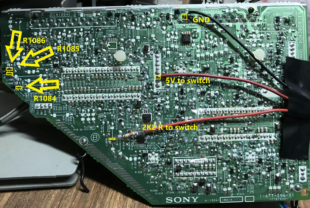
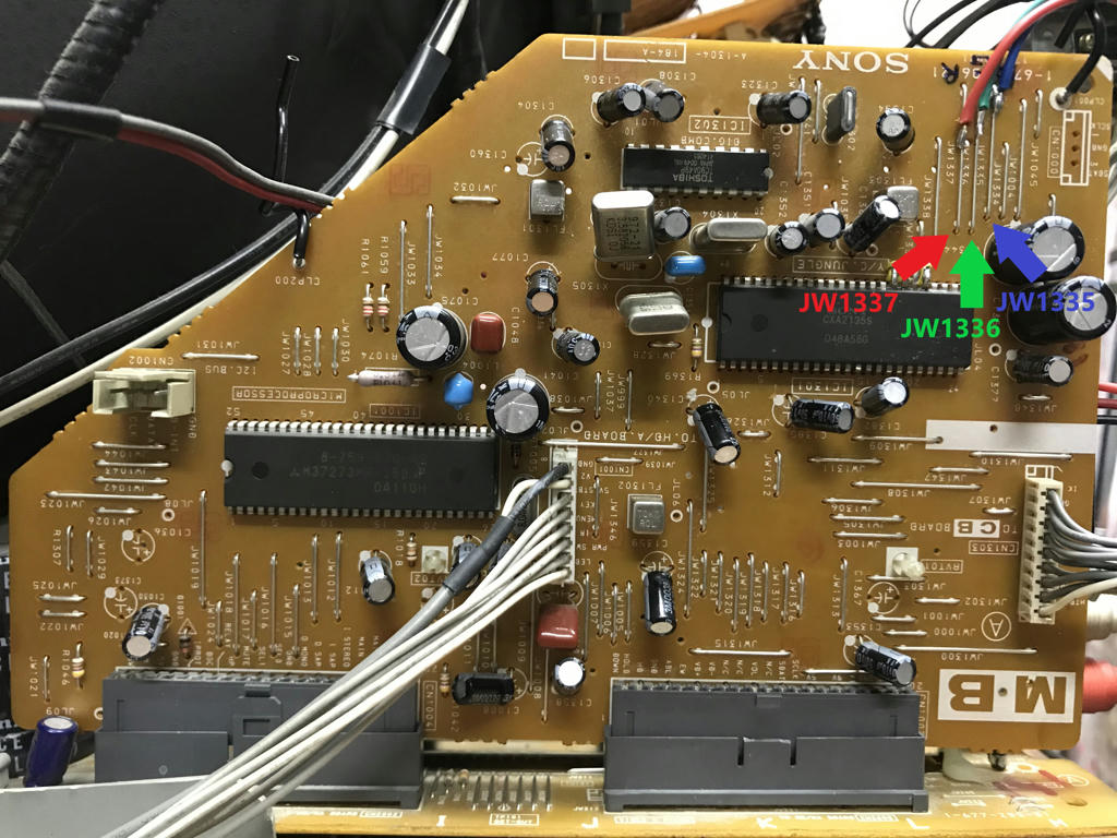
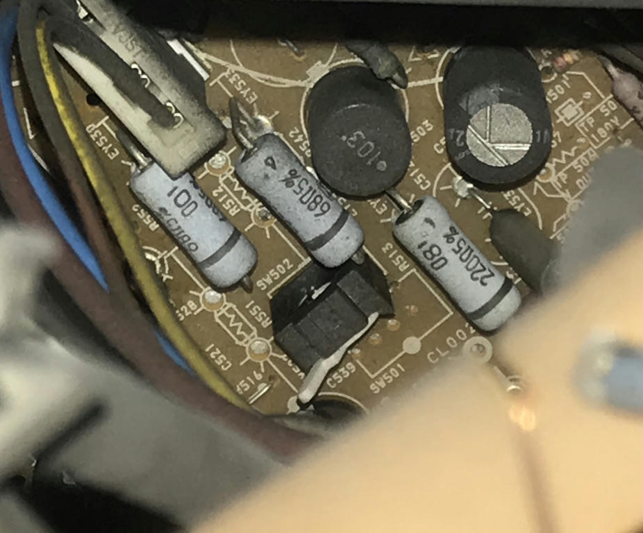
This is the part where the action occurs..
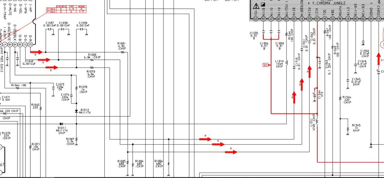
I lifted the legs for RGB2 and pin 29 (blanking?).. but i will wire them down again, as i have already identified some solder points for the MUX.
Doubt about Blanking
Referring to the datasheet..
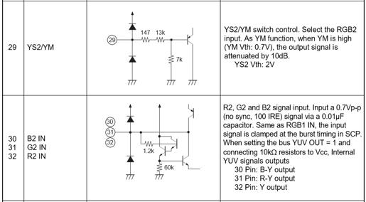
the blanking voltage is 2V...
is it ok to send 3V, as you usually do ?
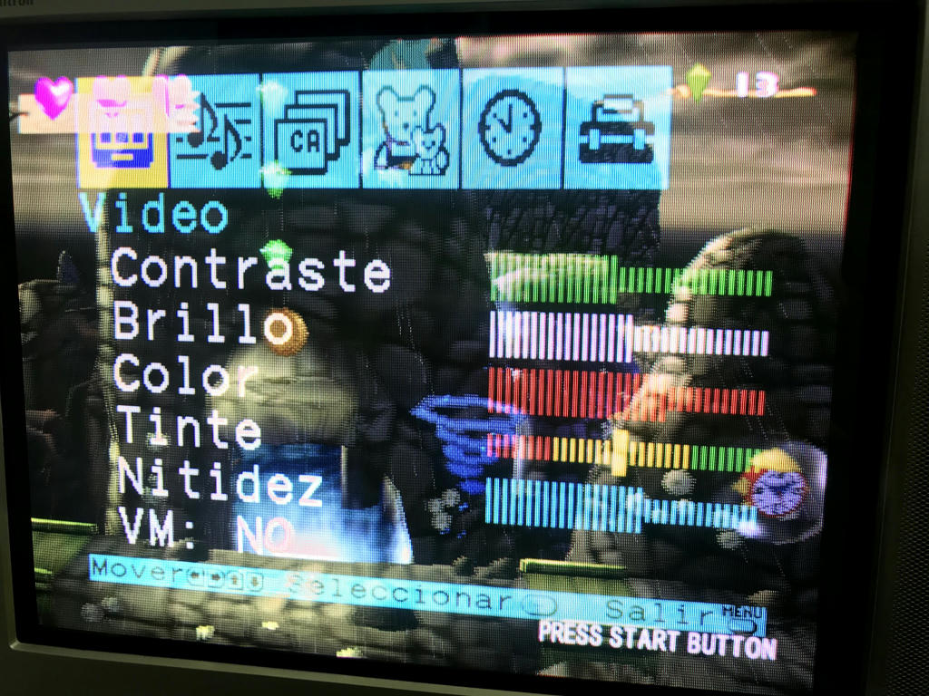
The main idea is to have an RGB TV for consoles and mainly AMIGA 500. So i could use a female DB9 in the back of the TV (for the Commodore cable i have), and for other consoles, use a "male DB9 to 4 rca" adaptor (R, G, B, Sync input) for homemade cables.
I guess termination on the input side is always needed, right? Not planning to use SCART by now.
I share CXA2135S DATASHEET and Sony KV 21 series BA5 chassis SERVICE MANUALS, for future reference.
http://www.mediafire.com/file/22xhhvoec ... l.pdf/file
http://www.mediafire.com/file/muee27078 ... S.pdf/file
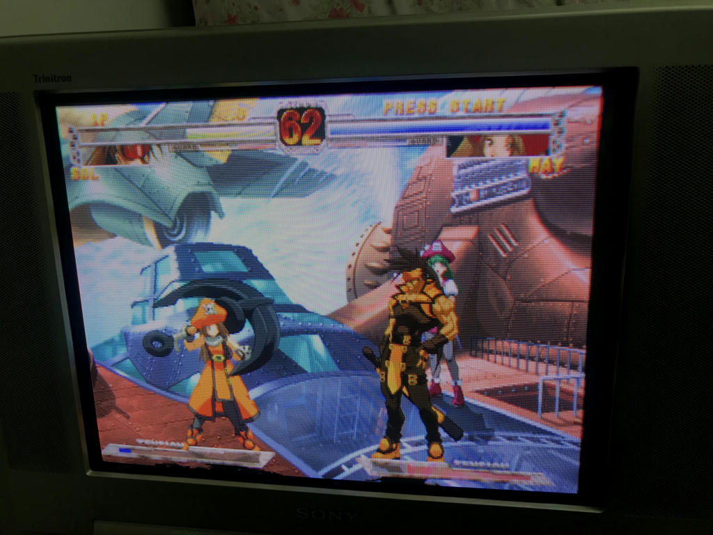
EDIT: i've made some progress and i deleted the confusion in this post. Next one will be the final diagram and working TV photos..


