I just modified my Sony KV-27FV300 and noticed now that I have what I can only describe as trails or smearing. This is very noticeable on games like Metroid where you have a dark black background and you are jumping around. I never noticed this before however... being that I was not using RGB in I more than likely was not displaying as black of a black so it was possibly not as noticeable. I plan to play around some tonight and run things the way I was previously, and then straight in with RGB (hopefully I can catch a pic of it).
I did not think this was due to too high or low of a resistor inline as I thought that would more so make the image darker.... but I wasn't sure if the resistor I used on the Blanking line was not the right value and maybe that is the possible issue (which I doubt but throwing it out there).
Since forum user DRC had already modded the same set I pretty much duplicated what he used and did. (although I'm having a hell of a time finding a good spot to solder the audio in on the same input) viewtopic.php?p=1382487#p1382487
TV RGB mod thread
Re: TV RGB mod thread
nintari wrote:I just modified my Sony KV-27FV300 and noticed now that I have what I can only describe as trails or smearing. This is very noticeable on games like Metroid where you have a dark black background and you are jumping around. I never noticed this before however... being that I was not using RGB in I more than likely was not displaying as black of a black so it was possibly not as noticeable. I plan to play around some tonight and run things the way I was previously, and then straight in with RGB (hopefully I can catch a pic of it).
I did not think this was due to too high or low of a resistor inline as I thought that would more so make the image darker.... but I wasn't sure if the resistor I used on the Blanking line was not the right value and maybe that is the possible issue (which I doubt but throwing it out there).
Since forum user DRC had already modded the same set I pretty much duplicated what he used and did. (although I'm having a hell of a time finding a good spot to solder the audio in on the same input) viewtopic.php?p=1382487#p1382487
For the horizontal smearing I would be looking at the electrolytic caps near the B+ and 200V lines from the flyback. I would be specifically focusing on C540, C541 and C705.
___________________________________________________
MarkOZLAD
OSD/External RGB Mux Diagram
OSD/External RGB Mux Resistor Value Table 0.7Vp-p : 0.5Vp-p
"Imagine toggle switch OSD modding a TV in 2019" - maxtherabbit
MarkOZLAD
OSD/External RGB Mux Diagram
OSD/External RGB Mux Resistor Value Table 0.7Vp-p : 0.5Vp-p
"Imagine toggle switch OSD modding a TV in 2019" - maxtherabbit

Re: TV RGB mod thread
So, this thread is amazing. I've been inspired to dive in and attempt my first RGB mod. 
I have a really nice Toshiba 14AF42 that I'd love to take a swing at, but since it's a little different from other Toshiba's I've seen people work on, I'm a little lost as to where to start. Can any veterans give me some direction as a first time RGB modder? The schematic and documentation for this model is here:
https://www.manualslib.com/manual/11060 ... ml?page=16
Thanks!
Re: TV RGB mod thread
Thanks for your help in this thread and the otherMarkOZLAD wrote:nintari wrote:I just modified my Sony KV-27FV300 and noticed now that I have what I can only describe as trails or smearing. This is very noticeable on games like Metroid where you have a dark black background and you are jumping around. I never noticed this before however... being that I was not using RGB in I more than likely was not displaying as black of a black so it was possibly not as noticeable. I plan to play around some tonight and run things the way I was previously, and then straight in with RGB (hopefully I can catch a pic of it).
I did not think this was due to too high or low of a resistor inline as I thought that would more so make the image darker.... but I wasn't sure if the resistor I used on the Blanking line was not the right value and maybe that is the possible issue (which I doubt but throwing it out there).
Since forum user DRC had already modded the same set I pretty much duplicated what he used and did. (although I'm having a hell of a time finding a good spot to solder the audio in on the same input) viewtopic.php?p=1382487#p1382487
For the horizontal smearing I would be looking at the electrolytic caps near the B+ and 200V lines from the flyback. I would be specifically focusing on C540, C541 and C705.
Re: TV RGB mod thread
IC101 is your micro controller. IC301 is your Jungle. R121, R122 and R123 (4700R) are the factory inline resistors on the OSD lines. R139, R140 and R141 (R1000) are the factory "ground" resistors.evewalker wrote:So, this thread is amazing. I've been inspired to dive in and attempt my first RGB mod.
I have a really nice Toshiba 14AF42 that I'd love to take a swing at, but since it's a little different from other Toshiba's I've seen people work on, I'm a little lost as to where to start. Can any veterans give me some direction as a first time RGB modder? The schematic and documentation for this model is here:
https://www.manualslib.com/manual/11060 ... ml?page=16
Thanks!
Mux resistors are 750R according to the lookup table in my signature (4700R with no diodes 0.7Vp-p)
It looks to be a pretty standard OSD mux candidate. Unfortunately it has surface mounted resistors which means you won't be able to use the twist method like the 8 Bit Guy mod. There are, however, great big jumpers on the RGB and blanking lines that would be great solder points. I think they are numbered W129-W132.
For blanking I'd run a 5V line through a switch and then into a diode and connect to the jumper.
___________________________________________________
MarkOZLAD
OSD/External RGB Mux Diagram
OSD/External RGB Mux Resistor Value Table 0.7Vp-p : 0.5Vp-p
"Imagine toggle switch OSD modding a TV in 2019" - maxtherabbit
MarkOZLAD
OSD/External RGB Mux Diagram
OSD/External RGB Mux Resistor Value Table 0.7Vp-p : 0.5Vp-p
"Imagine toggle switch OSD modding a TV in 2019" - maxtherabbit
Re: TV RGB mod thread
Mark/All,
Earlier in the thread there was talk about a mod to a Sharp (shart, lol) 25R-S100.
Here is the service manual for that TV https://diagramas.diagramasde.com/otros ... %20012.pdf
Mark drew up this awesome, detalied diagram https://drive.google.com/open?id=0BxXDE ... TdFWV9kQmc
The original poster, rx7turbo233 never posted (that I saw) more details or whether or not he had success with it.
I'm having some trouble trying to figure out exactly how to mod this. Here were your instructions:

14-r, 15-g, 16-b, 17-BLK. Great.
Here is the wiring under the IC201 chip:

According to this, these are resistors R802,805,804 on the RGB lines on the outside of the chip, -- under the chip the lines run towards IC2001 into Resistors R2024, R2025, R2026 respectively.
For the blanking pin, it runs through R816 on its way to R2027 by the IC2001 chip.
Here is an image of the underside of the board:

802, 805, and 804 don't exist, and aren't mentioned anywhere in the service manual components list.
R816 DOES exist, but it is ALSO not listed, so I hvae no idea what its value is.
Here's the part of the diagram that shows IC2001 output of R,G,B and BLK pins:

This is an image of the underside of the board by IC2001 where the R,G,B and BLK lines run to:

As you can see, these lines seem to run through (or touch) caps, but they don't exist. They aren't here, and there is nothing matching topside.
Here's a picture of the topside:

And here is the info on resistors:

So what we have is the RGB lines from IC2001 running through 6.8k resistors directly to the jungle, and the BLK runing through R816 (whose value is unknown) to the blanking pin on the jungle.
How would I proceed here?
Please note: I do not want to put a switch inline.. I'll be using this as an arcade monitor. I don't ever want to switch back to a non-rgb feed, so I am good with wiring this up for good to only accept 15khz input.
Earlier in the thread there was talk about a mod to a Sharp (shart, lol) 25R-S100.
Here is the service manual for that TV https://diagramas.diagramasde.com/otros ... %20012.pdf
Mark drew up this awesome, detalied diagram
The original poster, rx7turbo233 never posted (that I saw) more details or whether or not he had success with it.
I'm having some trouble trying to figure out exactly how to mod this. Here were your instructions:
so.. These are the pins in the diagram:Find capacitors that feed pins 14,15,16 of Jungle IC 201.
desolder the legs that are furthest from jungle, closest to OSD chip IC 2001.
Run wires from the the now empty capacitor leg holes to outside legs of switch.
find a resistor the OSD blanking line goes through. desolder a leg on the OSD side. Run a wire from empty hole to the outside leg of switch.
Run wires from legs of cap to inside leg of switch.
Run wire from leg of OSD blanking resistor to inside leg of switch.
Run wires from Scart RGB pins 7, 11 and 15 and 16 (for blanking) to other outside legs of switch. Put a 10K potentiometer on the blanking line.
Connect scart pin 21 to chassis ground. Connect pin 18 to chassis ground.
Terminate wires from scart RGB pins 7,11 and 15 to ground via 75 ohm resistors.
Connect scart pin 20 (Sync) and pin 17 (Sync ground) to the AV port.
Scart pin 6 is audio L, Scart pin 2 is audio R, scart pin 4 is audio ground. Connect to AV Audio port.
14-r, 15-g, 16-b, 17-BLK. Great.
Here is the wiring under the IC201 chip:
According to this, these are resistors R802,805,804 on the RGB lines on the outside of the chip, -- under the chip the lines run towards IC2001 into Resistors R2024, R2025, R2026 respectively.
For the blanking pin, it runs through R816 on its way to R2027 by the IC2001 chip.
Here is an image of the underside of the board:
802, 805, and 804 don't exist, and aren't mentioned anywhere in the service manual components list.
R816 DOES exist, but it is ALSO not listed, so I hvae no idea what its value is.
Here's the part of the diagram that shows IC2001 output of R,G,B and BLK pins:
This is an image of the underside of the board by IC2001 where the R,G,B and BLK lines run to:
As you can see, these lines seem to run through (or touch) caps, but they don't exist. They aren't here, and there is nothing matching topside.
Here's a picture of the topside:
And here is the info on resistors:
So what we have is the RGB lines from IC2001 running through 6.8k resistors directly to the jungle, and the BLK runing through R816 (whose value is unknown) to the blanking pin on the jungle.
How would I proceed here?
Please note: I do not want to put a switch inline.. I'll be using this as an arcade monitor. I don't ever want to switch back to a non-rgb feed, so I am good with wiring this up for good to only accept 15khz input.

Re: TV RGB mod thread
Thank you MarkOZLAD. It took me a few weeks but I was able to buy a spare board M off Ebay. So if I mess up I have an extra life.
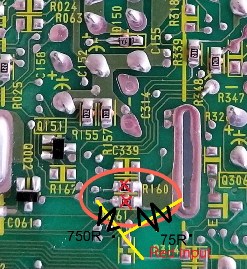
I am inclined towards removing resistors R159-R161 and insert my RGB lines there. If I go this route would activating close captions using the TV's menu with the remote be all that's required to turn on the blanking signal? (save the extra step of having to build a blanking switch).
I am inclined towards removing resistors R159-R161 and insert my RGB lines there. If I go this route would activating close captions using the TV's menu with the remote be all that's required to turn on the blanking signal? (save the extra step of having to build a blanking switch).
MarkOZLAD wrote:There appear to be a lot of via's (small holes that attach to circuits) on the board. I would be investigating whether they could be used as entry/solder points for through hole resistors. My "Plan A" would still be to remove R159, R160 and R161 and replacing them with two twisted together resistors (ala the 8 Bit Guy mod). In your case the CCD mux inlines would be 750 Ohm resistors that would be twisted to 75 Ohm resistors. (The resistors on the CCD lines, R162, R163 and R164 are 4700 so 750 can be looked up on my 0.7Vp-p cheat sheet in my signature)
Another option would be to remove R159, R160 and R161, insert 750 Ohm resistors into the vias that are attached, then run these to the RGB inputs and do your 75 ohm termination at the input. (RCA/BNC/Scart/VGA).
For the diagram I drew for blanking I ignored the switch as it is trivial.

Re: TV RGB mod thread
buttersoft wrote:Not sure if anyone's posted this yet, but...
https://www.youtube.com/watch?v=cyHmBMI3zC0
I thought i respected this guy, but it turns out he's a clown.
hahaha.
don't be too hard on him, it's just not his thing
Re: TV RGB mod thread
OK, so for the 25RS-100 post above (look 3 posts back)...
There are no diodes or caps inbetween IC2001 (IX3528CE System Control) and the IC201 (Jungle IX3354CE) .. All lines (including blanking) have a 6.8k resistor on them inline between IC2001 and IC201.
I'm assuming based on this:

I should be using 1.1k Ohm resistors on the RGB lines (terminated to ground with 75ohm resistors), and inject this in the hole of the resistor on the leg CLOSEST to IC201. Does that sound right?
Any ideas for the blanking line? do I just shove 5v directly into the blanking pin? do I inject 5v high on the leg closest to IC2001 so it goes through the resistor? Do I need another or different resistor there?
For 5V source, looks like I can clean 5v off Pin 3 of IC771 (5V Regulator), from topside jumper 906. Does that sound right?


For reference, the Jungle IC is equivalent to Sanyo LA76843N, datasheets here: https://pdf1.alldatasheet.com/datasheet ... 6843N.html
There are no diodes or caps inbetween IC2001 (IX3528CE System Control) and the IC201 (Jungle IX3354CE) .. All lines (including blanking) have a 6.8k resistor on them inline between IC2001 and IC201.
I'm assuming based on this:
I should be using 1.1k Ohm resistors on the RGB lines (terminated to ground with 75ohm resistors), and inject this in the hole of the resistor on the leg CLOSEST to IC201. Does that sound right?
Any ideas for the blanking line? do I just shove 5v directly into the blanking pin? do I inject 5v high on the leg closest to IC2001 so it goes through the resistor? Do I need another or different resistor there?
For 5V source, looks like I can clean 5v off Pin 3 of IC771 (5V Regulator), from topside jumper 906. Does that sound right?
For reference, the Jungle IC is equivalent to Sanyo LA76843N, datasheets here: https://pdf1.alldatasheet.com/datasheet ... 6843N.html
Re: TV RGB mod thread
That won’t work. Closed caption will only send blanking signals when it’s trying to draw characters.cargo wrote:If I go this route would activating close captions using the TV's menu with the remote be all that's required to turn on the blanking signal? (save the extra step of having to build a blanking switch
___________________________________________________
MarkOZLAD
OSD/External RGB Mux Diagram
OSD/External RGB Mux Resistor Value Table 0.7Vp-p : 0.5Vp-p
"Imagine toggle switch OSD modding a TV in 2019" - maxtherabbit
MarkOZLAD
OSD/External RGB Mux Diagram
OSD/External RGB Mux Resistor Value Table 0.7Vp-p : 0.5Vp-p
"Imagine toggle switch OSD modding a TV in 2019" - maxtherabbit
Re: TV RGB mod thread
Philips 14gl1319 very bad image after OSD / Ext RGB mod.
I don't know what I did wrong but the image only appears dark and with a lot of interference.
Please help me I have some pictures.
https://imgur.com/oiOWKEd
https://imgur.com/qRVTtGq
https://imgur.com/fRM5gZ3
https://imgur.com/nRIrpMO
https://imgur.com/KtjNwm7
https://imgur.com/fyixoq7
https://imgur.com/1NdtZ7N
https://imgur.com/4xx0HOe
Re: TV RGB mod thread
hello! I'm looking into rgb modding my tiny KV-9PT20. I'm a bit confused as I only see Red, Green and Blank from the jc to the osd (Pins 15, 16 and 17). On the osd side, I see rgb on pins 45-47 but Blue is not connected with anything. Any thoughts would be appreciated
https://imgur.com/a/6aE0lP3
https://imgur.com/a/6aE0lP3
Re: TV RGB mod thread
looking for some possible help, I've been reading through but still have a long way to go to read all of this thread
I recently modded a Sony KV-27FV300 and used the components another user in that thread suggested, but I have an odd issue when blanking is turned on, so I'm not sure if i possibly wired things backwards, have a bad resistor or what. I believe it was a 2k2Ohm resistor I used for the blanking.
When blanking is on the screen has a ghost to it, when it is off... it doesn't (see pics in link below)
https://imgur.com/a/TGt79zZ
Re: TV RGB mod thread
I have not seen that issue.
Did you follow the BA-5D chassis thread? That thread is entirely related to that specific TV.
viewtopic.php?f=6&t=63622
Please carefully review this post:
viewtopic.php?f=6&t=63622&start=78
It’s a detailed walkthrough with images on my mod of that TV, a KV-27FV300. If you use that guide and wire to the jumpers I indicate in that thread you should be GOLDEN.
That noise could be from a dirty 5V source or if you are running your wires too close to the flyback. Are you able to get a picture, but just have that noise?
Re: TV RGB mod thread
yes I posted the mod in that thread and linked to picsmgerety wrote:I have not seen that issue.
Did you follow the BA-5D chassis thread? That thread is entirely related to that specific TV.
viewtopic.php?f=6&t=63622
Please carefully review this post:
viewtopic.php?f=6&t=63622&start=78
It’s a detailed walkthrough with images on my mod of that TV, a KV-27FV300. If you use that guide and wire to the jumpers I indicate in that thread you should be GOLDEN.
That noise could be from a dirty 5V source or if you are running your wires too close to the flyback. Are you able to get a picture, but just have that noise?
I think it was you and DRC that had pretty much all the info I needed
Re: TV RGB mod thread
Haha, my bad.. Sorry man, I've read your posts there already.. I actually love your implementation with the switch on the front.yes I posted the mod in that thread and linked to pics
I think it was you and DRC that had pretty much all the info I needed
I don't know if it's related, but I had issues (see earlier in the BA-5D thread) with interference that I couldn't figure out that ended up being from dirty power in the computer i was using. It was resulting in noise over the VGA port. I finally figured it out when I connected the VGA to a monitor instead of the TV and got the same crap. Replacing the power supply completely cleared it up.
Beyond that, I don't know what else it could be. I'd assume it's a bad ground or a dirty source from something, but I am a complete novice when it comes to electronics -- I'm a developer not an electrical engineer. I can read and research enough to accomplish some things (i've recapped an arcade monitor, done a tube swap, RGB modded a TV, etc), but once it all falls down I don't really know enough to diagnose.
One thing for sure.. Resistors dont' have polarity, so there is no "backwards".
Re: TV RGB mod thread
Oh I know that on the resistor, I was instead not thinking and thought if I put the resistor on the wrong side....but even then it would still technically work as it is still inline. been a rough few days mah brain is shot lol. I changed wiring so I may use some of the metal tape I have to help shield the cables some (the type used on ducts...I would guess it would work...)mgerety wrote:Haha, my bad.. Sorry man, I've read your posts there already.. I actually love your implementation with the switch on the front.yes I posted the mod in that thread and linked to pics
I think it was you and DRC that had pretty much all the info I needed
I don't know if it's related, but I had issues (see earlier in the BA-5D thread) with interference that I couldn't figure out that ended up being from dirty power in the computer i was using. It was resulting in noise over the VGA port. I finally figured it out when I connected the VGA to a monitor instead of the TV and got the same crap. Replacing the power supply completely cleared it up.
Beyond that, I don't know what else it could be. I'd assume it's a bad ground or a dirty source from something, but I am a complete novice when it comes to electronics -- I'm a developer not an electrical engineer. I can read and research enough to accomplish some things (i've recapped an arcade monitor, done a tube swap, RGB modded a TV, etc), but once it all falls down I don't really know enough to diagnose.
One thing for sure.. Resistors dont' have polarity, so there is no "backwards".
-
undone.evil
- Posts: 11
- Joined: Sun Jul 14, 2019 4:34 am
Re: TV RGB mod thread
hello, im trying to rgb mod a RCA television and am having trouble with the RGB_MUX_MOD. i can get RGB on the screen but i cant get the OSD to work its either one or the other. one thing i have noticed is that the gemstar ic that outputs the OSD outputs the RGB at 0.3~0.5 volts im wondering if this could be part of my problem.
heres a link to the wiring diagram
https://elektrotanya.com/ge_27gt630tx51 ... ad.html#dl
thank you
heres a link to the wiring diagram
https://elektrotanya.com/ge_27gt630tx51 ... ad.html#dl
thank you
Re: TV RGB mod thread
Let me start by saying I'm not a fan of these Sanyo "LA76" jungles, they've given me trouble in the past.undone.evil wrote:hello, im trying to rgb mod a RCA television and am having trouble with the RGB_MUX_MOD. i can get RGB on the screen but i cant get the OSD to work its either one or the other. one thing i have noticed is that the gemstar ic that outputs the OSD outputs the RGB at 0.3~0.5 volts im wondering if this could be part of my problem.
heres a link to the wiring diagram
https://elektrotanya.com/ge_27gt630tx51 ... ad.html#dl
thank you
This TV has an OSD circuit that doesn't fit the regular pattern.
I'll take an educated guess at how to mod it...
I would target R26461, R26459 and R26458 as my OSD grounding resistors. I wouldn't bother with maths, I would just remove them and replace with 1KR and 75R twisted together (if through hole) 1KR untwisted leg goes to jungle, untwisted leg of 75R to ground. The RGB would be injected at the twist between the 1KR and 75R.
For blanking I would wire from a 5V source through a 470R and onto the leg of R26458 that isn't grounded.
___________________________________________________
MarkOZLAD
OSD/External RGB Mux Diagram
OSD/External RGB Mux Resistor Value Table 0.7Vp-p : 0.5Vp-p
"Imagine toggle switch OSD modding a TV in 2019" - maxtherabbit
MarkOZLAD
OSD/External RGB Mux Diagram
OSD/External RGB Mux Resistor Value Table 0.7Vp-p : 0.5Vp-p
"Imagine toggle switch OSD modding a TV in 2019" - maxtherabbit
-
undone.evil
- Posts: 11
- Joined: Sun Jul 14, 2019 4:34 am
Re: TV RGB mod thread
MarkOZLAD your suggestion on the 1k resistors worked great in mixing the signals. i had already removed the resistors and built the circuit you suggested but i had used 150r instead of 1kr.
now the problem im having is the OSD is super bright but the external RGB is very dim could i use lower resistors say 500r~800r to bring the external signal back up. i understand how the voltage divider works in respect to the OSD signal but i am not getting how it is effecting the external RGB signal.
thank you
Re: TV RGB mod thread
Maybe we should try re-engineering the OSD RGB circuit to be more like what we’re used to. I’ll get back to you when I can.
___________________________________________________
MarkOZLAD
OSD/External RGB Mux Diagram
OSD/External RGB Mux Resistor Value Table 0.7Vp-p : 0.5Vp-p
"Imagine toggle switch OSD modding a TV in 2019" - maxtherabbit
MarkOZLAD
OSD/External RGB Mux Diagram
OSD/External RGB Mux Resistor Value Table 0.7Vp-p : 0.5Vp-p
"Imagine toggle switch OSD modding a TV in 2019" - maxtherabbit
Re: TV RGB mod thread
undone.evil wrote:MarkOZLAD your suggestion on the 1k resistors worked great in mixing the signals. i had already removed the resistors and built the circuit you suggested but i had used 150r instead of 1kr.
now the problem im having is the OSD is super bright but the external RGB is very dim could i use lower resistors say 500r~800r to bring the external signal back up. i understand how the voltage divider works in respect to the OSD signal but i am not getting how it is effecting the external RGB signal.
thank you
hmmm, you could try potentiometers instead of the resistors.
Here is another option I think might work. Try and get your set to work like most others for OSD RGB.
1) Remove the following components:
R26486
R26487
R26489
R26488
Q26405
R26484
2) Replace R26444, R26445, R26446 with 1K resistors
3) Use 100R twisted with 75R in R26459, R26460, R26461
4) Jumper the red OSD circuit - jumper removed R26488 and from base to collector holes from Q26405 so red circuit now has continuity.
___________________________________________________
MarkOZLAD
OSD/External RGB Mux Diagram
OSD/External RGB Mux Resistor Value Table 0.7Vp-p : 0.5Vp-p
"Imagine toggle switch OSD modding a TV in 2019" - maxtherabbit
MarkOZLAD
OSD/External RGB Mux Diagram
OSD/External RGB Mux Resistor Value Table 0.7Vp-p : 0.5Vp-p
"Imagine toggle switch OSD modding a TV in 2019" - maxtherabbit
-
undone.evil
- Posts: 11
- Joined: Sun Jul 14, 2019 4:34 am
Re: TV RGB mod thread
ill give this a try in a bit. all of the components are surface mount on a separate 3"x3" double sided pcb so its a pain to work on.
i have been wondering why the red circuit is the only one with an amp and is tied to the G and B lines. do you have any insight on this
i have been wondering why the red circuit is the only one with an amp and is tied to the G and B lines. do you have any insight on this
Re: TV RGB mod thread
No idea.undone.evil wrote:ill give this a try in a bit. all of the components are surface mount on a separate 3"x3" double sided pcb so its a pain to work on.
i have been wondering why the red circuit is the only one with an amp and is tied to the G and B lines. do you have any insight on this
Have you go a chip number for the micro controller so we can maybe find a datasheet?
___________________________________________________
MarkOZLAD
OSD/External RGB Mux Diagram
OSD/External RGB Mux Resistor Value Table 0.7Vp-p : 0.5Vp-p
"Imagine toggle switch OSD modding a TV in 2019" - maxtherabbit
MarkOZLAD
OSD/External RGB Mux Diagram
OSD/External RGB Mux Resistor Value Table 0.7Vp-p : 0.5Vp-p
"Imagine toggle switch OSD modding a TV in 2019" - maxtherabbit

Re: TV RGB mod thread
Hey MARKOZLAD,
Can you take a peek at my (admittedly image heavy) posts above on page 91 and let me know if that all seems right (for the Sharp mod). I’m going to attempt that mod this week and would love some feedback.
Can you take a peek at my (admittedly image heavy) posts above on page 91 and let me know if that all seems right (for the Sharp mod). I’m going to attempt that mod this week and would love some feedback.
Re: TV RGB mod thread
mgerety wrote:Hey MARKOZLAD,
Can you take a peek at my (admittedly image heavy) posts above on page 91 and let me know if that all seems right (for the Sharp mod). I’m going to attempt that mod this week and would love some feedback.
From my research the IX3354CEN is a clone of the Sanyo LA76843N chip. As mentioned before, I don't have much luck with this family of chips, mostly because they have OSD Brightness and Contrast settings that are often set in a way that doesn't suit analog RGB and often there is no way to change in them in service menus....
Secondly, please destroy that earlier diagram I made. I can't stand the OSD snip and I'm pretty sure it is wrong anyway.
Let's get blanking out of the way first, take a 5V line from the 5V regulator IC771 pin3, put it through a 6800R and tie it into the blanking circuit somewhere on the jungle side of R2027...Perhaps the leg of R2027 closest to the jungle. Can install a switch in between if you like.
Ok, so the RGB lines look more difficult. There are no caps or OSD grounding/voltage dividing resistors....This is unusual and normally says digital OSD to me but hey, it's an old Sharp TV, let's have a crack anyway.
I'd be looking to intercept the RGB at R2024, R2025, R2026 by removing them (you might want to save them to build a circuit with). Unfortunately the resistors aren't evenly placed so we can't put a 3 pin 0.1" header in the holes closest to micro controller, maybe a 2 pin header and run a wire to the hole for R2024.
I'd use some prototyping board to build the RGB mux circuit. Starting from the microcontroller side I'd have the OSD inline resistors (could re-use the factory ones maybe), then the calculated mux resistors and 75R going to ground. RGB inserted between. Then I'd have the RGB signals go through 0.1uF caps and back into the holes for R2024, R2025, R2026 that are closest to the jungle. Note you will need to run a connection to ground as well.
I'll try and draw up a quick and dirty diagram shortly.
Will it work? I have no idea.
A QUICK THOUGHT....
Before you go to all this trouble, you might be best off to just try and get external RGB working. Perhaps wire up the blanking and then lift the legs of R2024, R2025, R2026 that are closest to the jungle and inject 75R terminated RGB via 0.1uF caps into the holes, sync into AV. This should tell you if it's even moddable.
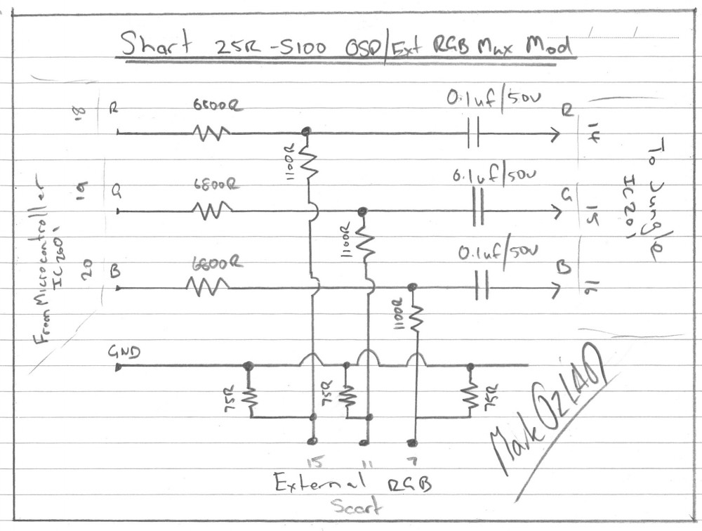
Note: The 6800R/1100R shown on diagram could be swapped out with any resistor pairing listed on my 0.7Vp-p OSD/External RGB Mux spreadsheet.
___________________________________________________
MarkOZLAD
OSD/External RGB Mux Diagram
OSD/External RGB Mux Resistor Value Table 0.7Vp-p : 0.5Vp-p
"Imagine toggle switch OSD modding a TV in 2019" - maxtherabbit
MarkOZLAD
OSD/External RGB Mux Diagram
OSD/External RGB Mux Resistor Value Table 0.7Vp-p : 0.5Vp-p
"Imagine toggle switch OSD modding a TV in 2019" - maxtherabbit
Re: TV RGB mod thread
Can't find a datasheet. It appears that the key number is VY21684C.undone.evil wrote:got a picture
It appears to be 5V logic so I hope my suggested method can work.
___________________________________________________
MarkOZLAD
OSD/External RGB Mux Diagram
OSD/External RGB Mux Resistor Value Table 0.7Vp-p : 0.5Vp-p
"Imagine toggle switch OSD modding a TV in 2019" - maxtherabbit
MarkOZLAD
OSD/External RGB Mux Diagram
OSD/External RGB Mux Resistor Value Table 0.7Vp-p : 0.5Vp-p
"Imagine toggle switch OSD modding a TV in 2019" - maxtherabbit
-
buttersoft

- Posts: 383
- Joined: Sun Jul 24, 2016 7:49 am
Re: TV RGB mod thread
Yer, he knows far, far more than i do about electronics. He just has zero experience with CRT, so he's writing off that Samsung without even trying it. If you can tolerate that setting it up is a bit finicky, it has one of the nicest consumer tubes i've seen for arcade use.vol.2 wrote:buttersoft wrote:Not sure if anyone's posted this yet, but...
https://www.youtube.com/watch?v=cyHmBMI3zC0
I thought i respected this guy, but it turns out he's a clown.
hahaha.
don't be too hard on him, it's just not his thing
Re: TV RGB mod thread
It also has an unpopulated RGB scart....buttersoft wrote: If you can tolerate that setting it up is a bit finicky, it has one of the nicest consumer tubes i've seen for arcade use.
___________________________________________________
MarkOZLAD
OSD/External RGB Mux Diagram
OSD/External RGB Mux Resistor Value Table 0.7Vp-p : 0.5Vp-p
"Imagine toggle switch OSD modding a TV in 2019" - maxtherabbit
MarkOZLAD
OSD/External RGB Mux Diagram
OSD/External RGB Mux Resistor Value Table 0.7Vp-p : 0.5Vp-p
"Imagine toggle switch OSD modding a TV in 2019" - maxtherabbit