Is that the one that gets replaced with a tantalum capacitor? If so, yes I replaced it and it did nothing.Syntax wrote:Did you remove the ceramic cap near the LM1117 1.3v LDO?
Sent from my SM-G955U using Tapatalk

Is that the one that gets replaced with a tantalum capacitor? If so, yes I replaced it and it did nothing.Syntax wrote:Did you remove the ceramic cap near the LM1117 1.3v LDO?
Thats wrong? I have nothing connected in the Component input, only in the ega/cga input, do I have to change something in the code or in the configuration to make it work? Or just don't work with my resolution or my LCD? Please if someone can help I will be very grateful.*!**!**!**!*<reset>
Scanning inputs for sources...
Activity detected, input:Component
*!***
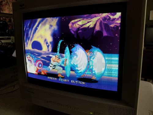
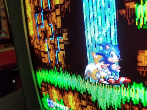
I soldered the Debug Pin, VIN, GND, SDA and SCL in the GBS and worked great in component in my moded Snes and moded Genesis and I got fantastic results, the image is great, but in my arcade board still not working, probably because of the game is for 25 inch medium resolution arcade monitor the resolution is 512x400 and speed 24Khz, the log in the Serial Monitor says:rama wrote:Hey,
I need more details to help you with this.
What type of sync signal are you using? The RGB port supports combined sync on the "S" pin and separate H+V.
Please post a complete log of gbscontrol starting up and then failing to detect the source correctly.
You will need to connect your pc with Arduino IDE for this, then use the Serial Monitor, so you get the complete logs.
And I got no video, messing with the Development options (SyncWatcher) I get a scrambled image like this:userprefs.txt opened
loading from preset slot 5: /preset_ntsc.5
post preset done (preset id: 1)(custom)
.Base 1796 Best:1801 Fieldrate 59.857
SOG Lvl:11
..*!**!**!**!**!*<reset>
Scanning inputs for sources ...
Activity detected, input:RGBS/HV
lost..
Activity detected, input:RGBS/HV
lost..
Activity detected, input:RGBS/HV
lost..
Activity detected, input:RGBS/HV
lost..
Activity detected, input:RGBS/HV
lost..
Activity detected, input:RGBS/HV
lost..
Activity detected, input:RGBS/HV
lost..
Activity detected, input:RGBS/HV
lost..
Activity detected, input:RGBS/HV
lost..
Activity detected, input:RGBS/HV
lost..
Activity detected, input:RGBS/HV
lost..

I can see that the firmware is struggling to get the resolution and speed right, but it's not working, would there be something I could do to fix and make it work on this arcade board?sync watcher off
loading from preset slot 5:no preset file for this source
post preset done (preset id:1)
SOG Lvl: 11
Unknown timing!
Unknown timing!
Activity detected, input:RGBS/HV
lost..
Unknown timing!
Unknown timing!
Activity detected, input:RGBS/HV
lost..
Unknown timing!
Unknown timing!
Activity detected, input:RGBS/HV
lost..
Unknown timing!
Unknown timing!
Yes the service manual of the arcade board says it is CSync, the V and H are combined in the same cable, the CGA conector has Redgun, Greengun, Bluegun, GNDgun and Video Sync (CSync). The original Firmware works without problem, maybe if I send the parameters of the signal the video mode could be implemented.rama wrote:Eduardoml:
So this looks like CSync or Sync on Composite, not separate H/V.
The problem then is indeed the unknown video mode.
So I know why it fails, but right now there nothing I can do from here.
I would need such a board / sync source, and implement the video mode.
As long as the vertical period is indeed around 60Hz, there won't be any big issues.
The GBS can handle it just fine, but it needs to have software support for it.
Note:
Even if you provided H+V Sync, then gbscontrol would bypass the signal fine, but the display still couldn't handle it.
So it has to be software supported upscaling mode.
that's badass - I had been putting off modding mine since those caps looked like a pain in the dick to replacerama wrote:I just updated the development branch with the new sync processing.
https://github.com/ramapcsx2/gbs-contro ... evelopment
The most important change for users is that the SOG capacitors can (and should) stay at the default 100nF now.
I'm aware that reverting this hardware mod is difficult, because the solder area isn't as clean as with a stock board.
The change is great for new users and stock boards, which are the vast majority. I hope you guys understand.
If you want to undo the mod, use 2 x 100nF 0605 capacitors (anything between 39nF and 100nF works well).
For removing the 1nF caps, I would recommend to add solder to both sides of the part, so you can more easily heat both sides at the same time.
Once removed, check for bridges (fix them with wick or solder sucker if needed) and clean up the area.
If you have 0605 parts, installing them should be easy now.
Sync processing is very different now and there are a few benefits beside just "being stable".
With the new SOG clamp, it became possible to use the SOG separator better.
I see better behaviour with Mega Drives, with H-PLL lock when using Composite Video Sync, etc.
Hope to get some test results from you guys
Possibly, yes. I don't have the time to investigate that now but if you want, these 3 registers are currently used for tuning:Ryoandr wrote:Any chance of having adjustable gamma boost when scanlines are enabled ? I always find it a tiny bit too bright.
Code: Select all
GBS::VDS_Y_GAIN::write(GBS::VDS_Y_GAIN::read() + 0x30); // 3_35 more luma gain
GBS::MADPT_VIIR_COEF::write(0x14); // set up VIIR filter 2_27
GBS::MADPT_Y_MI_OFFSET::write(0x28); // 2_0b offset (mixing factor here)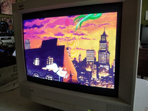

If you set the deinterlacer to bob, I believe that turns it off?retromaniak wrote:Hi, I wanted to ask if there would be an option to disable de-interlacing. I am referring here primarily to the Playstation Portable console which, on the component cable, transmits the image progressively, and so the controller tries to remove the interlace that does not exist.


