Thank you! I'll order some scart sockets and do some research this weekend.MarkOZLAD wrote:It appears highly likely that this TV can be RGB modded. It will be worthwhile you doing the research into how it is done.Radiantsvgun wrote:I have a Tosh 27 pure flat that I'm wondering if it can be RGB modded. I think I have the correct part of the service manual, but I'm at a loss of where to go from here. It is a component TV if that matters.
https://www.manualslib.com/manual/69969 ... =20#manual
Hint: OSD/External RGB mix (nee mux) method....
TV RGB mod thread
-
Radiantsvgun

- Posts: 39
- Joined: Fri Jul 25, 2008 1:46 am
- Location: Atlanta, GA
Re: TV RGB mod thread

Re: TV RGB mod thread
Radiantsvgun wrote:Thank you! I'll order some scart sockets and do some research this weekend.MarkOZLAD wrote:It appears highly likely that this TV can be RGB modded. It will be worthwhile you doing the research into how it is done.Radiantsvgun wrote:I have a Tosh 27 pure flat that I'm wondering if it can be RGB modded. I think I have the correct part of the service manual, but I'm at a loss of where to go from here. It is a component TV if that matters.
https://www.manualslib.com/manual/69969 ... =20#manual
Hint: OSD/External RGB mix (nee mux) method....
Here's the datasheet for the jungle IC. https://pdf1.alldatasheet.com/datasheet ... 283FP.html
Those OSD RGB lines appear to be for digital RGB though? unless I'm mistaken.

Re: TV RGB mod thread
Says FastBlank. I'd give it a crack.
Re: TV RGB mod thread
The inline resistor/ground resistor/capacitor pattern suggests analog RGB.Syntax wrote:Says FastBlank. I'd give it a crack.
___________________________________________________
MarkOZLAD
OSD/External RGB Mux Diagram
OSD/External RGB Mux Resistor Value Table 0.7Vp-p : 0.5Vp-p
"Imagine toggle switch OSD modding a TV in 2019" - maxtherabbit
MarkOZLAD
OSD/External RGB Mux Diagram
OSD/External RGB Mux Resistor Value Table 0.7Vp-p : 0.5Vp-p
"Imagine toggle switch OSD modding a TV in 2019" - maxtherabbit
Re: TV RGB mod thread
Ok i know am currently working with an Akai TV, but someone just offered me a Sony KV-24FV12. I tried searching the forum to see if anyone had mentioned this TV before but it didn't turn up anything.
I thought i was good at identifying TV's that Could be modded but it still seems I've got more to learn.
Here is the service manual
http://go-gddq.com/upload/2010-04/10040915469189.pdf (Don't bother with the one on Manuals library as its broken,huge chunks missing)
I see the jungle with RGB IN but don't see any blanking or even where is ties in with the OSD to do the Switch method.
Can anyone take a look?
Re: TV RGB mod thread
Blanking is YS2/YM.Sammickk wrote:Ok i know am currently working with an Akai TV, but someone just offered me a Sony KV-24FV12. I tried searching the forum to see if anyone had mentioned this TV before but it didn't turn up anything.
I thought i was good at identifying TV's that Could be modded but it still seems I've got more to learn.
Here is the service manual
http://go-gddq.com/upload/2010-04/10040915469189.pdf (Don't bother with the one on Manuals library as its broken,huge chunks missing)
I see the jungle with RGB IN but don't see any blanking or even where is ties in with the OSD to do the Switch method.
Can anyone take a look?
Suitable for OSD/External RGB Mux method as are all Sony BA-5 BA-5D Chassis
___________________________________________________
MarkOZLAD
OSD/External RGB Mux Diagram
OSD/External RGB Mux Resistor Value Table 0.7Vp-p : 0.5Vp-p
"Imagine toggle switch OSD modding a TV in 2019" - maxtherabbit
MarkOZLAD
OSD/External RGB Mux Diagram
OSD/External RGB Mux Resistor Value Table 0.7Vp-p : 0.5Vp-p
"Imagine toggle switch OSD modding a TV in 2019" - maxtherabbit
-
arithmaldor

- Posts: 124
- Joined: Wed Jun 07, 2017 8:39 pm
Re: TV RGB mod thread
Re: TV RGB mod thread
Curious question, is 30 gauge wire too light weight for a TV RGB mod?
What gauge does everyone else use here?
What gauge does everyone else use here?
-
Einzelherz

- Posts: 1279
- Joined: Wed Apr 09, 2014 2:09 am
-
maxtherabbit

- Posts: 1763
- Joined: Mon Mar 05, 2018 4:03 pm
Re: TV RGB mod thread
has anyone ever tried YPbPr modding a 90s curved trinitron?
I was looking at one service manual for the kv-32s22, which uses the CXA2025AS Y/C/J, and it appears to take YUV at the correct levels from the PiP board... seems like a component mod for that jungle chip would be a breeze
I was looking at one service manual for the kv-32s22, which uses the CXA2025AS Y/C/J, and it appears to take YUV at the correct levels from the PiP board... seems like a component mod for that jungle chip would be a breeze
Re: TV RGB mod thread
Hello everyone,
I'm needing some help if anyone can. ...
I have a Toshiba mw27f51
I have the service manual and I have a decent idea of where to get my RGB and sync input for a scart mod. But I'd really like some guidance. Can anyone help?
I'm needing some help if anyone can. ...
I have a Toshiba mw27f51
I have the service manual and I have a decent idea of where to get my RGB and sync input for a scart mod. But I'd really like some guidance. Can anyone help?
Re: TV RGB mod thread
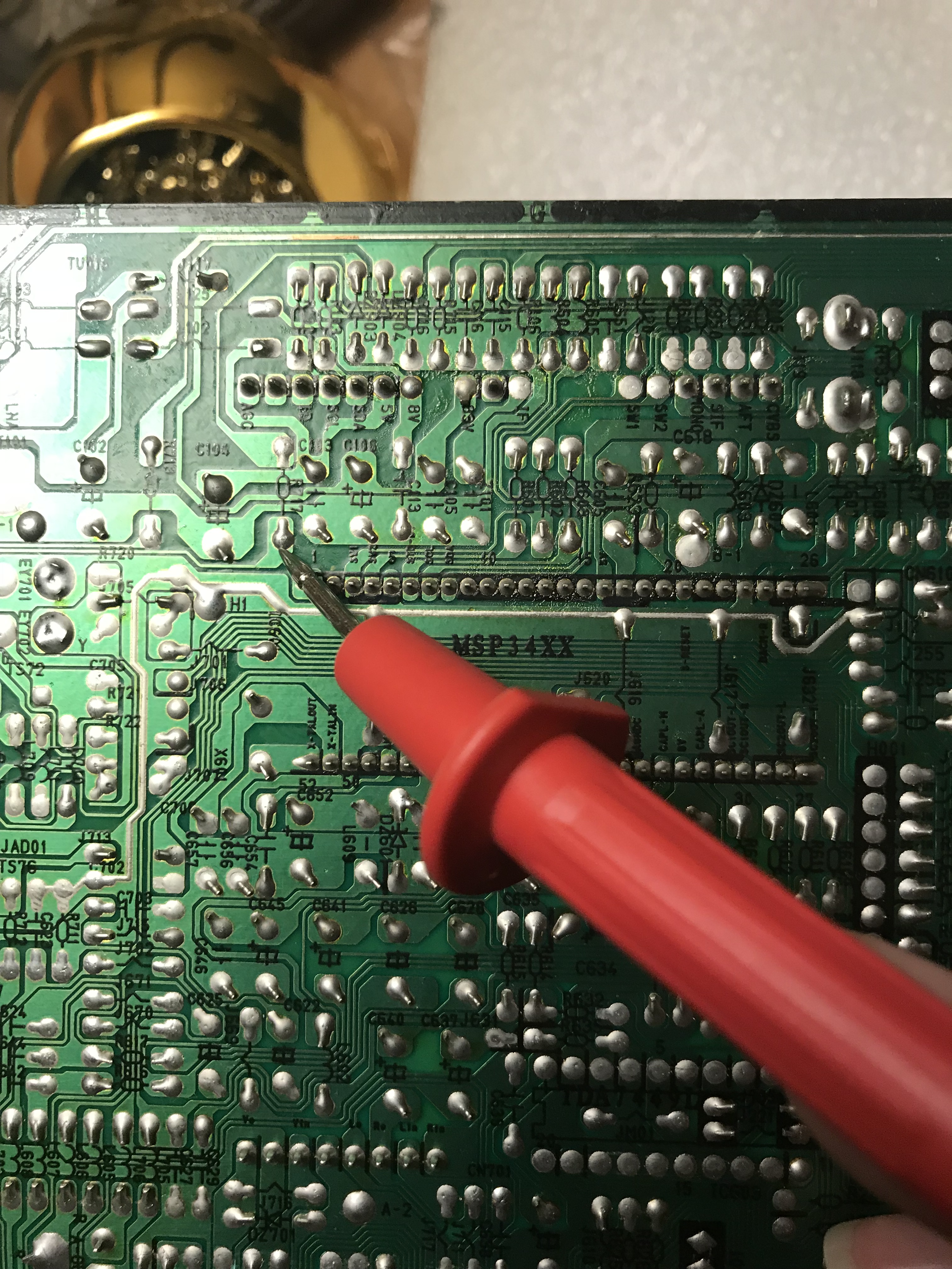
OK starting from Pin 8 on the board, I traced it to R717 on the board which is missing! looking beyond that (which you can see in the picture below) leads to a Diode, which IS in place and dumps into a pool of many different things as you can see in the picture, which sprouts to many things all over the board! is this a voltage rail supplying current to many different parts?MarkOZLAD wrote:Can you please trace out the Scart pin 8 circuit?
As for the switch, RGB is enabled via the scart pin 16 sending 1-3V through to the Fast Blanking Pin of the Jungle chip. Pin 8 of scart provides a 5-12V signal which is designed to automatically switch the TV to the Scart input (doesn't always work when modding).
Please review the Wikipedia article about Scart. It is always a great place to start. https://en.wikipedia.org/wiki/SCART
Spoiler
0 V–2 V means no signal, or internal bypass
4.5 V–7 V (nominal 6 V) means a widescreen (16:9) signal
9.5 V–12 V (nominal 12 V) means a normal (4:3) signal
the different consoles provide this when you turn them on? or is it the other way around and the board supplies the current when it senses the powered on console? i guess i don't understand which way the signal or currect in flowing.
How does it get these various ranges of current?
I'm at a loss as to what to do about this.
Re: TV RGB mod thread
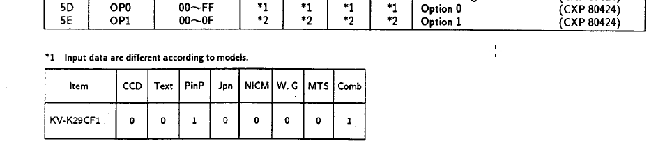
According to the CXA2025AS datasheet this will depend on whether the EY-SW register is set to 0 or 1. There may be a service menu switch to enable PIP input.maxtherabbit wrote:has anyone ever tried YPbPr modding a 90s curved trinitron?
I was looking at one service manual for the kv-32s22, which uses the CXA2025AS Y/C/J, and it appears to take YUV at the correct levels from the PiP board... seems like a component mod for that jungle chip would be a breeze
Adjustments for service menu listed in here
May need to find a model that had PIP and copy the Option Data settings from that set. see Page 19.
Last edited by MarkOZLAD on Tue Sep 25, 2018 2:29 am, edited 1 time in total.
___________________________________________________
MarkOZLAD
OSD/External RGB Mux Diagram
OSD/External RGB Mux Resistor Value Table 0.7Vp-p : 0.5Vp-p
"Imagine toggle switch OSD modding a TV in 2019" - maxtherabbit
MarkOZLAD
OSD/External RGB Mux Diagram
OSD/External RGB Mux Resistor Value Table 0.7Vp-p : 0.5Vp-p
"Imagine toggle switch OSD modding a TV in 2019" - maxtherabbit
Re: TV RGB mod thread
Are you sure that "pool" is not a ground plane? You can tell by putting one probe of multimeter on the end of the diode on the plane and another on the tuner cage. If it reads zero it's a ground plane.Sammickk wrote: OK starting from Pin 8 on the board, I traced it to R717 on the board which is missing! looking beyond that (which you can see in the picture below) leads to a Diode, which IS in place and dumps into a pool of many different things as you can see in the picture, which sprouts to many things all over the board! is this a voltage rail supplying current to many different parts?
After the diode, the Scart Pin 8 appears to go to the R715. Is this correct? Can you confirm with a multimeter?
I think there's a good chance R717 and R715 make up the voltage divider on the Scart pin 8. Can you measure R715?
___________________________________________________
MarkOZLAD
OSD/External RGB Mux Diagram
OSD/External RGB Mux Resistor Value Table 0.7Vp-p : 0.5Vp-p
"Imagine toggle switch OSD modding a TV in 2019" - maxtherabbit
MarkOZLAD
OSD/External RGB Mux Diagram
OSD/External RGB Mux Resistor Value Table 0.7Vp-p : 0.5Vp-p
"Imagine toggle switch OSD modding a TV in 2019" - maxtherabbit
Re: TV RGB mod thread
Is this the place to ask if a certain tv can be modded for RGB?
Re: TV RGB mod thread
You are correct that is a ground plane I did what you said and got a zero on the meter.MarkOZLAD wrote:Are you sure that "pool" is not a ground plane? You can tell by putting one probe of multimeter on the end of the diode on the plane and another on the tuner cage. If it reads zero it's a ground plane.
After the diode, the Scart Pin 8 appears to go to the R715. Is this correct? Can you confirm with a multimeter?
I think there's a good chance R717 and R715 make up the voltage divider on the Scart pin 8. Can you measure R715?
I see the trace now of the diode going to R715, i guess I wasn't squinting hard enough lol but yes it goes there. It reads 9.93k so a 10K resister?
I can't measure R717 as its not on the board. I guess they left that one off on purpose?
Re: TV RGB mod thread
From my experience the voltage dividers on Scart Pin 8 line reduce 12V to 5V. Based on this I think you should put a 14K Ohm resistor in R717.Sammickk wrote:
You are correct that is a ground plane I did what you said and got a zero on the meter.
I see the trace now of the diode going to R715, i guess I wasn't squinting hard enough lol but yes it goes there. It reads 9.93k so a 10K resister?
I can't measure R717 as its not on the board. I guess they left that one off on purpose?
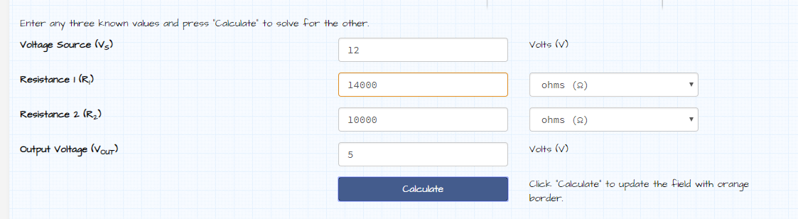
I have seen other sets drop it down towards 2.5V, which would be a 39K resistor for you..... So something from 14-39K. The LG MC-099A uses 15K/6.8K to make 12V into 3.75V, which would indicate a 22K resistor would be appropriate and in the middle ground.
Voltage division is a concept you really should try and understand. It is dead simple.
http://www.ohmslawcalculator.com/voltag ... calculator
If you start getting it switching into widescreen on some consoles (that output 5V on pin 8 ) there are options we can look at. I've helped a guy add a switch to force 4:3 mode before, it's easy. Using a 14K resistor option should minimise the chance of this happening because it will end up a higher voltage at the chip. Suck it and see I say.
___________________________________________________
MarkOZLAD
OSD/External RGB Mux Diagram
OSD/External RGB Mux Resistor Value Table 0.7Vp-p : 0.5Vp-p
"Imagine toggle switch OSD modding a TV in 2019" - maxtherabbit
MarkOZLAD
OSD/External RGB Mux Diagram
OSD/External RGB Mux Resistor Value Table 0.7Vp-p : 0.5Vp-p
"Imagine toggle switch OSD modding a TV in 2019" - maxtherabbit
-
maxtherabbit
- Posts: 1763
- Joined: Mon Mar 05, 2018 4:03 pm
Re: TV RGB mod thread
I'm picking up a free 32" curved trinitron later today that uses that chassis... hopefully it has PiPMarkOZLAD wrote:According to the CXA2025AS datasheet this will depend on whether the EY-SW register is set to 0 or 1. There may be a service menu switch to enable PIP input.maxtherabbit wrote:has anyone ever tried YPbPr modding a 90s curved trinitron?
I was looking at one service manual for the kv-32s22, which uses the CXA2025AS Y/C/J, and it appears to take YUV at the correct levels from the PiP board... seems like a component mod for that jungle chip would be a breeze
Adjustments for service menu listed in here
May need to find a model that had PIP and copy the Option Data settings from that set. see Page 19.
-
Diopter Doctor

- Posts: 20
- Joined: Sun Sep 16, 2018 2:16 am
Re: TV RGB mod thread
First CRT RGB Mod for me! 
I need some help on this Sony KV-K29MF1. (a 29" tube with sweet speakers)
link to the service manual: https://elektrotanya.com/sony_kv-k29mf1 ... nload.html
page 40 has the schematics like you'll see below.
OK, I've drawn out what I know so far and I have two issues.
#1. If I try to inject external RGB into the OSD signal (labeled RGB "IN 2" in my diagram) where should I attempt it?
I'm thinking on the OSD side of the 1 farad caps for the RGB lines? Or where the OSD ground resistors are now (after they're removed)?
#2. The jungle chip has two RGB "In" locations (labeled as RGB "IN 1" and "IN 2" in my diagram)
Does RGB "IN 1" look usable that way I can avoid the entire mux calculations?
RGB "IN 1" looks like it just connects to ground via a resistor from the schematic, which I find odd.
Although tracing each pin out on the PCB looks like they go to more places than just ground, so I don't know if that could even be used at all.
Any input is highly appreciated!
Schematic w/ Highlights
https://flic.kr/p/MGVE2H
Schematic By-Hand w/ Highlights
https://flic.kr/p/2anaX7s
Overview of PCB
https://flic.kr/p/2a5dKye
OSD Chip w/ traces
https://flic.kr/p/2a5dLpH
OSD Chip plain
https://flic.kr/p/MGVLMB
Jungle Chip w/ traces
https://flic.kr/p/MGVM9P
Jungle Chip plain
https://flic.kr/p/2a5dLCZ
Sorry for all the URL's. I'm new to shmups so I don't know how put JUST the pictures up here.
-
maxtherabbit
- Posts: 1763
- Joined: Mon Mar 05, 2018 4:03 pm
Re: TV RGB mod thread
ended up being the slightly older version of the chassis that uses the CXA2025S - it does have PiP and still takes analog YUV on the same pins, but it doesn't have the EY-SW register to worry aboutmaxtherabbit wrote:I'm picking up a free 32" curved trinitron later today that uses that chassis... hopefully it has PiPMarkOZLAD wrote:According to the CXA2025AS datasheet this will depend on whether the EY-SW register is set to 0 or 1. There may be a service menu switch to enable PIP input.maxtherabbit wrote:has anyone ever tried YPbPr modding a 90s curved trinitron?
I was looking at one service manual for the kv-32s22, which uses the CXA2025AS Y/C/J, and it appears to take YUV at the correct levels from the PiP board... seems like a component mod for that jungle chip would be a breeze
Adjustments for service menu listed in here
May need to find a model that had PIP and copy the Option Data settings from that set. see Page 19.
it also has an analog RGB OSD, so I guess I can bang out both inputs
I'll post back whenever I get around to it, probably be a while
Re: TV RGB mod thread
The G3F is one djcalle and I have investigated before. We have not done a mod but we did find that some schematics list a CN103 Teletext port that could be suitable for RGB and Blanking injection.Diopter Doctor wrote:First CRT RGB Mod for me!
I need some help on this Sony KV-K29MF1. (a 29" tube with sweet speakers)
link to the service manual: https://elektrotanya.com/sony_kv-k29mf1 ... nload.html
page 40 has the schematics like you'll see below.
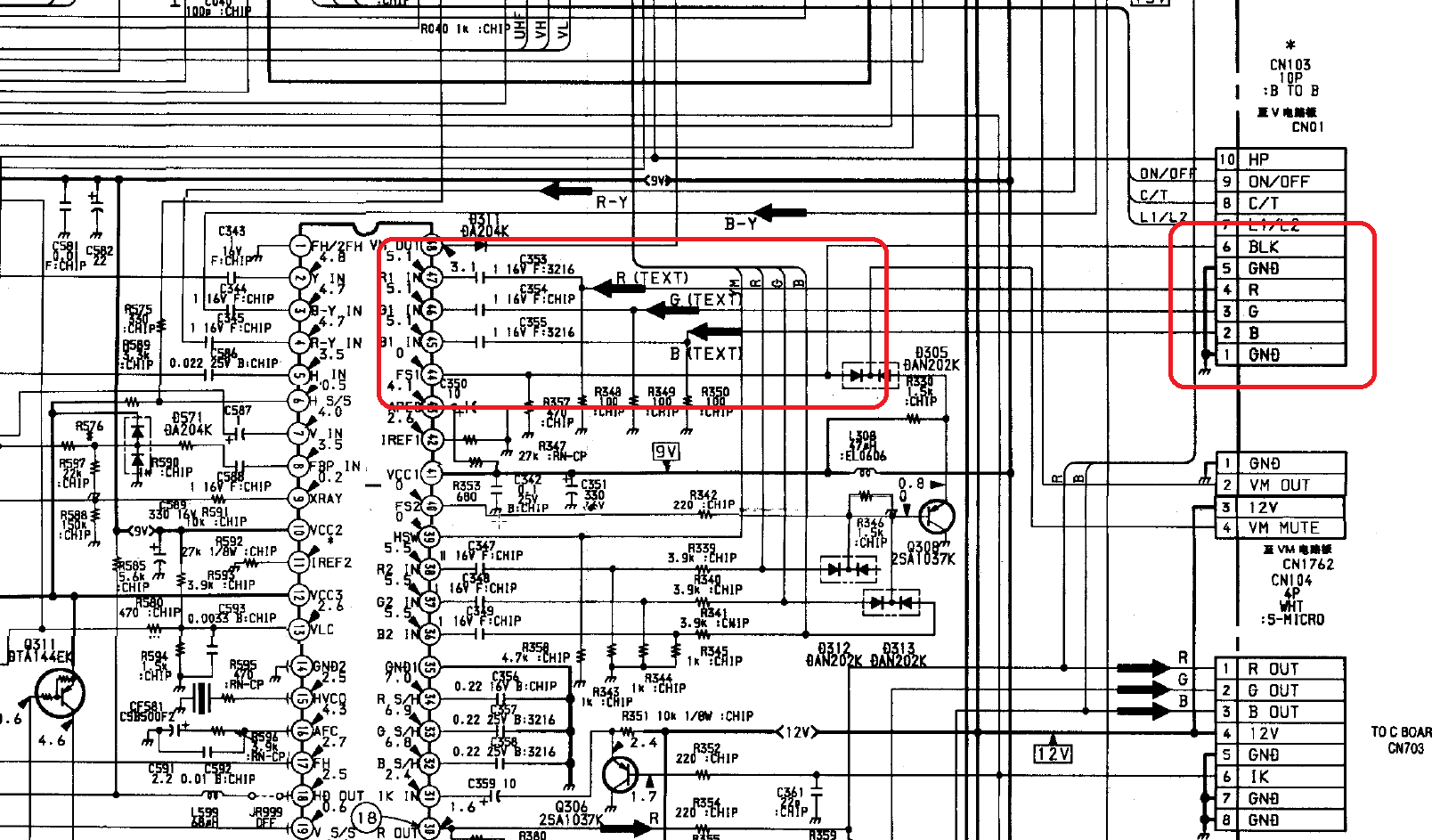
I would remove R348, R349 and R350 and use 75R terminations on the RGB lines, or leave them in place and use 300R terminations (using parallel resistancs to alter 100R to 75R)
May need to change the service options.
Hope this is of help.
___________________________________________________
MarkOZLAD
OSD/External RGB Mux Diagram
OSD/External RGB Mux Resistor Value Table 0.7Vp-p : 0.5Vp-p
"Imagine toggle switch OSD modding a TV in 2019" - maxtherabbit
MarkOZLAD
OSD/External RGB Mux Diagram
OSD/External RGB Mux Resistor Value Table 0.7Vp-p : 0.5Vp-p
"Imagine toggle switch OSD modding a TV in 2019" - maxtherabbit
Re: TV RGB mod thread
Well I cracked open a Broken VCR, and 3 Radios looking for a 14k resistor, no luck but can't I just link a 10k and 4k over the board? Won't that just do the same thing? PS again I live in a crummy town in WV, we have no radio shack or any store that would carry stuff like this. I know I could just order it online from mouser but I'm kinda having fun learning about electronics as I go through this.MarkOZLAD wrote:If you start getting it switching into widescreen on some consoles (that output 5V on pin 8 ) there are options we can look at. I've helped a guy add a switch to force 4:3 mode before, it's easy. Using a 14K resistor option should minimise the chance of this happening because it will end up a higher voltage at the chip. Suck it and see I say.
Re: TV RGB mod thread
Yep, 10K + 4K in series will give 14K.Sammickk wrote:Well I cracked open a Broken VCR, and 3 Radios looking for a 14k resistor, no luck but can't I just link a 10k and 4k over the board? Won't that just do the same thing? PS again I live in a crummy town in WV, we have no radio shack or any store that would carry stuff like this. I know I could just order it online from mouser but I'm kinda having fun learning about electronics as I go through this.MarkOZLAD wrote:If you start getting it switching into widescreen on some consoles (that output 5V on pin 8 ) there are options we can look at. I've helped a guy add a switch to force 4:3 mode before, it's easy. Using a 14K resistor option should minimise the chance of this happening because it will end up a higher voltage at the chip. Suck it and see I say.
I didn't even think about standard resistor sizes! Where is my mind? 15K, 16K, 18K or 20K would all likely be fine too if you find them
___________________________________________________
MarkOZLAD
OSD/External RGB Mux Diagram
OSD/External RGB Mux Resistor Value Table 0.7Vp-p : 0.5Vp-p
"Imagine toggle switch OSD modding a TV in 2019" - maxtherabbit
MarkOZLAD
OSD/External RGB Mux Diagram
OSD/External RGB Mux Resistor Value Table 0.7Vp-p : 0.5Vp-p
"Imagine toggle switch OSD modding a TV in 2019" - maxtherabbit
Re: TV RGB mod thread
Ok I just ended up joining a 4.7k and a 10k. I read it after I soldered it into the board and it reads correctly. So now you think I just need to wire up my SCART connecter and cross fingers fire it up and hope it works? Can’t think of anything else I should check before I reassemble the TV? Oh by the way I only have 30 gauge wire... will that work or do I need to use thicker?MarkOZLAD wrote:Yep, 10K + 4K in series will give 14K.Sammickk wrote:Well I cracked open a Broken VCR, and 3 Radios looking for a 14k resistor, no luck but can't I just link a 10k and 4k over the board? Won't that just do the same thing? PS again I live in a crummy town in WV, we have no radio shack or any store that would carry stuff like this. I know I could just order it online from mouser but I'm kinda having fun learning about electronics as I go through this.MarkOZLAD wrote:If you start getting it switching into widescreen on some consoles (that output 5V on pin 8 ) there are options we can look at. I've helped a guy add a switch to force 4:3 mode before, it's easy. Using a 14K resistor option should minimise the chance of this happening because it will end up a higher voltage at the chip. Suck it and see I say.
I didn't even think about standard resistor sizes! Where is my mind? 15K, 16K, 18K or 20K would all likely be fine too if you find them
-
maxtherabbit
- Posts: 1763
- Joined: Mon Mar 05, 2018 4:03 pm
Re: TV RGB mod thread
I'd say minimum of 28awg for RGB lines, thicker the betterSammickk wrote: Ok I just ended up joining a 4.7k and a 10k. I read it after I soldered it into the board and it reads correctly. So now you think I just need to wire up my SCART connecter and cross fingers fire it up and hope it works? Can’t think of anything else I should check before I reassemble the TV? Oh by the way I only have 30 gauge wire... will that work or do I need to use thicker?
Re: TV RGB mod thread
CAT5e has 24 gauge wire inside... I don’t know if each of the 8 wires is shielded though, would that work?maxtherabbit wrote:I'd say minimum of 28awg for RGB lines, thicker the betterSammickk wrote: Ok I just ended up joining a 4.7k and a 10k. I read it after I soldered it into the board and it reads correctly. So now you think I just need to wire up my SCART connecter and cross fingers fire it up and hope it works? Can’t think of anything else I should check before I reassemble the TV? Oh by the way I only have 30 gauge wire... will that work or do I need to use thicker?
-
maxtherabbit
- Posts: 1763
- Joined: Mon Mar 05, 2018 4:03 pm
Re: TV RGB mod thread
maybe, it's almost always solid core though, which at that gauge can be difficult to safely attach to small PCB pads without ripping them offSammickk wrote:CAT5e has 24 gauge wire inside... I don’t know if each of the 8 wires is shielded though, would that work?maxtherabbit wrote:I'd say minimum of 28awg for RGB lines, thicker the betterSammickk wrote: Ok I just ended up joining a 4.7k and a 10k. I read it after I soldered it into the board and it reads correctly. So now you think I just need to wire up my SCART connecter and cross fingers fire it up and hope it works? Can’t think of anything else I should check before I reassemble the TV? Oh by the way I only have 30 gauge wire... will that work or do I need to use thicker?
Re: TV RGB mod thread
Oh I thought I’d seen people recommended using solid and not using stranded.
24 is pretty thin though I can’t imagine it being that difficult but I have no choice unless I want to order on the net and wait for another 4 days for it to come in. I’m on vacation this week from work and was hoping to spend allota time working on all this.
24 is pretty thin though I can’t imagine it being that difficult but I have no choice unless I want to order on the net and wait for another 4 days for it to come in. I’m on vacation this week from work and was hoping to spend allota time working on all this.
-
maxtherabbit
- Posts: 1763
- Joined: Mon Mar 05, 2018 4:03 pm
Re: TV RGB mod thread
Solid 24awg is stiff and heavy. Attaching it is not the problem, sometimes the weight and rigidity of the wire causes board damageSammickk wrote:Oh I thought I’d seen people recommended using solid and not using stranded.
24 is pretty thin though I can’t imagine it being that difficult but I have no choice unless I want to order on the net and wait for another 4 days for it to come in. I’m on vacation this week from work and was hoping to spend allota time working on all this.
Re: TV RGB mod thread
At some point you'll have to....Sammickk wrote:So now you think I just need to wire up my SCART connecter and cross fingers fire it up and hope it works?
___________________________________________________
MarkOZLAD
OSD/External RGB Mux Diagram
OSD/External RGB Mux Resistor Value Table 0.7Vp-p : 0.5Vp-p
"Imagine toggle switch OSD modding a TV in 2019" - maxtherabbit
MarkOZLAD
OSD/External RGB Mux Diagram
OSD/External RGB Mux Resistor Value Table 0.7Vp-p : 0.5Vp-p
"Imagine toggle switch OSD modding a TV in 2019" - maxtherabbit