GBS 8200/8220 CFW Project
Re: GBS 8200/8220 CFW Project
@rama but i wonder about lag, what hdmi conversion would introduce.
Re: GBS 8200/8220 CFW Project
Rama:rama wrote: I still want to descramble CSYNC into H+V SYNC though :p
But yeah, it is very difficult with a general approach.
This might be something, section: How can I build a circuit which converts composite sync signal to HSYNC and VSYNC?
http://www.epanorama.net/faq/vga2rgb/vgamonitor.html
By adding two gates after LM1881 it makes a "real" HSYNC by combining CSYNC and VSYNC.
Code: Select all
           |--------------|----------------------  Composite (if you need it)
           |              |    |-----\
           | |-----\      -----|      \
Composite ---|      \          | AND   |---------  Hsync
             | NAND  |o--------|      /
Vsync -------|      /          |-----/
           | |-----/
           |
           |-------------------------------------  Vsync
Re: GBS 8200/8220 CFW Project
The circuit looks nicely simple, but I don't see how it could eliminate half scanline pulses around vsync.
At best, this could be used with very wide coast margins, so that these pulses get ignored.
But at that point, the circuit is arguably worse than just using the built-in stripper.
About the docs, sure I have them. The register map is okay and useful, but the programming guide is very rudimentary.
What's explained is often given as "golden settings" (aka: use these magic numbers and the sync processor will work!), with no theory or explanation on how the chip actually works, or what any of the countless parameters do.
It's really a shame, because the chip is very flexible and has many different ways to chain all the processing units together.
HDMI transcoders (these simple types) don't add any lag, but of course, a TV might.
Re: GBS 8200/8220 CFW Project
ordered a cheapo vga to hdmi + audio transcoder.
@rama how much memory left in mcu with all the code, would data for lcd to show like (preset, resolution) would still fit (just for visual experience)
thinking now to fit everything into one package and into enclosure, having hard time to find any cases locally, still don't have 3d printer, don't want to order print from services, because of trial and error designing it to fit everything.
thinking about to extending inputs and outputs to case, add switches for sync separator and scanline options or just program a controller to do everything via menu and buttons and show on lcd. add audio out and if don't want to use hdmi option. leave vga output too (vga wouldn't be a problem but on my new tv in other city there's no vga inputs, so that's why i want to add hdmi). Oh and to add power via micro usb and another usb micro straight to mcu (debug/programing port) for firmware updates.
tl;dr: want to create nice package for whole project.
Overall thanks rama for your great work.
By the way having problems with diy slg, maybe someone knows, sometimes slg doesn't work as intended in high res modes (done with tutorial from mmmonkey), but biggest question is that scanlines gets distorted from EMI when i hover my hand over slg. Dunno what's happening there.
Re: GBS 8200/8220 CFW Project
That sounds great! Wish you best of luck getting all this done 
Okay, so first thing is "Will that LCD fit?"
The ESP8266 has plenty of RAM, flash and CPU cycles left. It surely can accommodate another library.
What the chip isn't so good at, is GPIO.
It doesn't have a whole lot of them to begin with, and I already use 3 for I2C and debug.
I haven't looked into typical requirements for LCD modules, but you should for something that doesn't require a lot of pins.
You need to look around a little to really determine how many and which GPIO are still available.
But all in all, adding an LCD with info printouts should be very much doable!
Mechanical construction, switches and such:
The YPbPr input is straight forward. Plug in a PS2 or XBOX or such, and sync + video will be dealt with.
Then there is RGBHV and RGBS.
On the GBS, the HSYNC line is shared with "S" (CSYNC, Luma or CVideo sync).
There is a small problem here: This shared input line could carry 5Vpp levels from a PC, or variable from 0.3Vpp to maybe 3Vpp "dirty sync" from a games console.
Your sync stripper would have to leave real HSYNC alone, but process the game console sync.
One way to deal with it is to just declare the device for one type of input, then never connect the other.
Another way is a switch fro the user to operate, that either passes the signal through, or switches in the sync stripper.
Yet another option is to make sure that each game console uses a good CSYNC signal, and leave out the sync stripper + switch.
Cases isn't my forte. I hope someone designs something 3D printable one day?
Power:
Well, it depends on the extra devices that should go into the box, of course.
You probably want to feed the system 5V / 1A+.
5V is nice because it can be down regulated on the GBS to 3.3V, but be used as is for the sync stripper that typically runs on 5V.
A wholly stacked system with stripper, additional VGA > HDMI chip and ESP8266 dev board may draw up to 0.9A at 5V.
Add the LED module and you arrive at maybe 5W total.
This is too much for regular USB power, unfortunately (only 2.5W). Newer USB ports may be good for it though.
The diy SLG you built had some kind of floating inputs issue in the design.
I don't want to blame mmmonkey too much for this. At least he provided useful instructions on how to build these.
Back when I built it, it was the only available design!
Anyway, I had the same issue and it was floating inputs on one of the chips.

Re: GBS 8200/8220 CFW Project
This is why I added a scart input to my GBS and cut the Hsync trace near the input and bridged it with a 470R.rama wrote:
Then there is RGBHV and RGBS.
On the GBS, the HSYNC line is shared with "S" (CSYNC, Luma or CVideo sync).
There is a small problem here: This shared input line could carry 5Vpp levels from a PC, or variable from 0.3Vpp to maybe 3Vpp "dirty sync" from a games console.
Your sync stripper would have to leave real HSYNC alone, but process the game console sync.
One way to deal with it is to just declare the device for one type of input, then never connect the other.
Another way is a switch fro the user to operate, that either passes the signal through, or switches in the sync stripper.
Yet another option is to make sure that each game console uses a good CSYNC signal, and leave out the sync stripper + switch.
If i was going to connect Vsync to the inputs should it also have a resistor around 470R?
Still shocked something with a VGA input cannot accept TTL..
-
NoAffinity

- Posts: 1081
- Joined: Mon May 07, 2018 5:27 pm
- Location: Escondido, CA, USA
Re: GBS 8200/8220 CFW Project
I was futzing around with equipment tonight, and thought I'd grab some comparative video, to take screenshots from. VGA output from supergun to OSSC. Stock GBS was set to 1368x768, and reported by OSSC as 796p. The GBS-Control driven GBS, as we've discussed previously, outputs a signal that OSSC sees as a 1001p. All else was equal, including lossless video capture. No question the quality of the image is much better with GBS-Control taking...well....control. :p
Click through to see full-size image: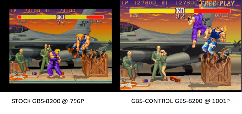 What this doesn't capture is the artifact and other nonsense that the stock GBS puts out, which GBS-Control does away. There is also noticeable lag with the stock GBS, and less (non-existant) with GBS-Control. Things I think we've already well documented, but just mentioning them because these differences were glaring while I was going through this exercise.
Click through to see full-size image:
Spoiler
Re: GBS 8200/8220 CFW Project
@rama it's i2c oled display with 4wires, 3.3v, gnd and 2 digitals. Before using my mcu i had used it for weather station. So should be no problem as long theres space left on chip. Will try at the end of the month to write additional code on top of yours to test it. I just think it would be nice addition
Re: GBS 8200/8220 CFW Project
Alright, you should be able to find another 2 free GPIO 
Your code is probably collecting some data every couple of loop()s, then update the LCD.
You need to make sure that your code doesn't block the loop, so that WiFi + housekeeping stuff is not disturbed.
Feel free to add more variables to the runTimeInformation struct that's defined early in the sketch.
It's likely that I can re-use your collected data for display in the web ui
Re: GBS 8200/8220 CFW Project
NoAffinity:
If you feel like it, more captures would be great!
There aren't enough demos available that show the improvement over similar scalers / stock software.
A capture card is too expensive for me to buy :/
If you feel like it, more captures would be great!
There aren't enough demos available that show the improvement over similar scalers / stock software.
A capture card is too expensive for me to buy :/

Re: GBS 8200/8220 CFW Project
I could do some more captures if you like. It would probably be cool to have some comparison screenshots, like you say, to show people the improvement when using gbscontrol
Re: GBS 8200/8220 CFW Project
Yeah sure, please do
-
NoAffinity
- Posts: 1081
- Joined: Mon May 07, 2018 5:27 pm
- Location: Escondido, CA, USA
Re: GBS 8200/8220 CFW Project
I captured some video from Street Fighter 2 Hyper Fighting arcade PCB, via stock GBS-8200 and GBS-Control GBS-8200. There is a link in the description pointing to the previous GBS-Control video I posted, and that video has the complete setup outlined. The only difference between the two pieces of footage in this video is GBS stock vs. GBS-Control.
https://youtu.be/mNx6bsjmsuU
https://youtu.be/mNx6bsjmsuU
Re: GBS 8200/8220 CFW Project
Nice work, but I feel a side by side comparison would probably be more effective.
-
NoAffinity
- Posts: 1081
- Joined: Mon May 07, 2018 5:27 pm
- Location: Escondido, CA, USA
Re: GBS 8200/8220 CFW Project
I considered that, but then thought that because its not the same footage, side by side could be more distracting than useful. I'm sure there's a way to improve on it, but nothing quick or easy (relatively speaking) comes to mind.Syntax wrote:Nice work, but I feel a side by side comparison would probably be more effective.
Re: GBS 8200/8220 CFW Project
It's a good, clean comparison between the two. Many thanks!
Your capture setup is very forgiving to the original firmware's flaws.
It looks pretty good on first glance, and the switchover to gbs-control doesn't appear to be very different.
It's probably because the window is pretty small, and the source footage has only limited scrolling (almost none vertical).
If you ever connect a SNES or some such, it would probably be more obvious in those games.
(Especially since stock tends to not even work with SNES. It just refuses the slightly odd CSYNC with a "No Signal" :p)
Best of luck with your tuning efforts! The 12Mhz seems to be fast enough. Scrolling couldn't be smoother, I think
Edit:
Does the game have a color test / calibration mode? It would probably show the black / white crush of stock very well!
Constantly slow scrolling backgrounds will show the deinterlace artefacts.
-
NoAffinity
- Posts: 1081
- Joined: Mon May 07, 2018 5:27 pm
- Location: Escondido, CA, USA
Re: GBS 8200/8220 CFW Project
^Good notes. I will see if I can dig something up to show the test screens and with some more scrolling. Street Fighter Ex2 might do the trick, as it has 3d backgrounds with lots of motion in attract mode.
I contemplated scaling the image so it isn't so small, but I'm also combatting having to capture on a 2560x1440 canvas so youtube compression doesn't destroy the quality. The two coupled together do result in a smaller image than may be fully useful. I'll tinker with the concepts on the next capture, and see if I can't find a sweet spot that doesn't overly scale the image and potentially introduce non-existent problems.
And you're right, some of the GBS native shortcomings aren't fully apparent in that capture, whereas it was pretty bad on my 49" LED. The biggest think I notice in the comparison is the GBS stock output produces more of a pastel painting effect, with all the smoothed edges and such, whereas GBS-Control produces noticeably sharper pixels. And of course the processing delay, which doesn't get represented in a simple video capture, but is noticeable first-hand.
Re: GBS 8200/8220 CFW Project
@rama
https://www.tindie.com/products/8bitgas ... a-adapter/
Is this something (h sync side) that would help to provide correct h and v sync as you wanted ?
https://www.tindie.com/products/8bitgas ... a-adapter/
Is this something (h sync side) that would help to provide correct h and v sync as you wanted ?
Re: GBS 8200/8220 CFW Project
Yeah, this device looks perfect for the job.
It uses an improved revision of the old LM1881 sync stripper, one that supposedly restores H + V sync perfectly.
The price is fair, especially considering that each one will be built by hand.
Those advanced sync strippers can be hard to source as well, depending on how many one needs.
I think this is indeed a better replacement for the sync strike.
(Fine print: I can't afford this either, so the whole rebuilt H + V idea is untested. It may not work any better than the default, or it may be a big improvement ;p)
Re: GBS 8200/8220 CFW Project
By description it just looks like single chip solution taking sync from scart and pushing it to vga hv. So i will need yo check datasheet of that lm. Most of this guy stuff is just simple diy projects put on pcb thats it.
@rama just a dumb question whats the difference if we use hv syncs ?
And if i build diy one what should o expect ? Better sync ? Should i feed then this via input vga ?
Im open for tests if it improves overall performance of upscaler and this sync stripping helps to improve gbs control
@rama just a dumb question whats the difference if we use hv syncs ?
And if i build diy one what should o expect ? Better sync ? Should i feed then this via input vga ?
Im open for tests if it improves overall performance of upscaler and this sync stripping helps to improve gbs control
Re: GBS 8200/8220 CFW Project
With combined sync, the VSYNC portion of the signal is malformed, as part of the specification.
This requires the scaler to ignore sync pulses before, mid, and after VSYNC.
The chip can do this without much trouble, but it disturbs the timing regeneration slightly.
Using separate sync, all the pulses can be assumed valid, all the time.
This simplifies the setup and lets the H-PLL (timing regen) lock onto the source constantly.
The chip can measure timings better then, run on less power, and deliver a sharper picture with less noise.
But all in all, it is not something that I expect people will actually see in their picture.
It's all pretty much a theoretical thing.
Basically, get this device if you want peace of mind that the scaler can operate optimally
Re: GBS 8200/8220 CFW Project
so I know have a more workable setup (theres an LM1881 on the underside), still WIP

I did some rapid tests with 1 chip SFC and MD on a VGA CRT, it's looking really nice, I do have some questions
320 wide games look really nice with 640x480+scanlines, 256 wide look resonably good but do show some little artifacts, is it possible to have a wider horizontal res that might allow better scaling while keeping 480 height ? Cause scanlines get thinner with higher res (and if using an external scanline generator it would be better too, although some do have options for thicker scanlines).
MD is known to have a very large active area with big borders. If I set my monitor geometry to hide these borders, I start to get tube reflections and a milky white border appears on the right. Would it be possible to have black borders around the picture frame ? Also the left side is missing a few pixels.
Some SNES games (Jurassic Park, Kirby 3) use a 512 wide res with a vertical pattern to fake transparency. It's a bit of a mess when it's used. What can be done to have a cleaner look ?
Also noticed on the vertical bars pattern (color bleed) that 1280x960 looked fine, while 1280x720 had some uneven scaling, despite being the same horizontal res.
Scanlines are still enabled when switching from 240p to 480i. While very subtle, this amplifies flicker a bit. Is there a way to stop applying scanlines on 480i (automagically I mean).
I'll be soon consolizing a MVS, which are known to have badly formed sync and non standard refresh (AES has a slightly different crystal that brings it closer to NTSC standard) so more testing is ahead.
Re: GBS 8200/8220 CFW Project
another finding EL1883 clone of lm1881 with hsync output instead of csync
Re: GBS 8200/8220 CFW Project
Ryoandr:
The build looks good! What's the tiny USB board next to the NodeMCU?
You may want to shorten your wires when you finalize the build though. Long wires pick up noise.
Your questions regarding interference patterns, pixel artefacts and such at specific test images:
Every preset has to work with the limitations of pixel clock, available memory and scaling factors that are suitable.
For example, this is why the 720p and 1280x960 presets look different horizontally.
Less lines in 720p free up memory, so the ADC sampling clock is increased and a fitting scale factor is used.
Eventhough there are 1024 steps for scaling, only very few of those produce a mostly even image, for example in the bar pattern.
The challange is to find an exact multiple ADC sampling clock (I tune to PSX 320 px), and then find a fitting scale factor, so that
the image doesn't overrun into the blanking area or is too narrow.
The default presets therefore are a good compromise, and artefacts will appear in special test patterns.
I choose to go this route for the defaults, because the issues are much less apparent when actually playing games.
But I also give users options, so that you can create custom presets that work better with your sources.
You will find that each console needs slightly different adjustments, but they all can achieve near perfect test patterns, if you tweak enough.
The options you need are:
- PLL divider++ (ADC sampling clock)
- horizontal scale up / down (to reduce the now wider image, but you need to find a fitting value)
- picture left / right (to now fix the image position)
(I just noticed there's no PLL div-- yet ..)
The other options are potentially useful as well, of course.
MD border regions:
Yeah, I want to add a mask option.
It will simply extend the (display) horizontal / vertical blanking start / stop positions.
I'm just not sure yet how to make it simple to use and reliable at the same time.
Scanlines in 480i mode:
Well, they could be automatically toggled with a little delay of maybe 5 frames. This won't be too noticeable.
The issue is that I would need to know whether the source is interlaced or not, and this isn't so simple! ;p
So far all I can think of is that (only some) sources report 2 alternating values for vtotal, usually something like 262/263.
If I see this pattern over a few frames, that could be an indicator. Well, or bad sync. You never know :/
Edit: Oh, maybe the LM1881 odd/even output will work for this! Requires users to have one, of course.
The MVS works fine by the way. Timing spec differences are no issue for gbscontrol. It excels here
Re: GBS 8200/8220 CFW Project
the micro usb board is for powering via Vin pin, I don't remember exactly how but due to how the NodeMCU usb power is wired, this allows me to power from either usb via a 1A phone charger, or the barrel on the GBS (NodeMCU Vin pin can accept up to 10v).
There is some interference, but for now it's fine and it's minimal to be fair.
Thanks for the info, gonna try toying with settings and presets.
There is some interference, but for now it's fine and it's minimal to be fair.
Thanks for the info, gonna try toying with settings and presets.
Re: GBS 8200/8220 CFW Project
The LMH1981 seems to have good specs for sync separation.
http://www.ti.com/product/lmh1981/description
I checked inside my amiga rgb->vga adapter and to my surprise it's using separate H/V-sync already (going through a 74HCT14B) similar to the original Commodore's db23->hd15 adapter. Would it work to connect this way using the adapter and vga-cable to gbs vga-input w/ separate H/V-sync instead of using rgbs header with csync?
Re: GBS 8200/8220 CFW Project
74hct14 is an hex inverter. So thats not gonna help.
Lmh on the other hand ia very very small package, not a problem for me to solder it, but if el1883 does apropriate sync stripping and ia straight on replacement for lm1881 with hsync output, why not to try it
On other hand its voltage range is shorter than ti lm's
Edit: @rama if we use seperate h and v as sync does yours gbs control will work ? There wont be any issues or incompability ?
Re: GBS 8200/8220 CFW Project
Right now gbscontrol will detect activity on the vsync input and go into RGBHV bypass mode.
It may even work, but it won't be what you expected, I bet.
I haven't coded the control logic to deal with different sync schemes.
If it is RGBS, I assume low res. If it is RGBHV, I assume mid to high res.
This can be changed, but it should not simply be tacked on again.
This time, it really should be redesigned. And everyone likes starting from scratch, right? ;p
For that Amiga, the situation is probably the same. It will work, but go into RGBHV bypass.
The 74hct14 is probably there to act as a buffer. The GBS does the same, but uses a HC125 line driver.
Re: GBS 8200/8220 CFW Project
I like to start again fresh always, after a while in the name of a better successor. But it takes time and when it's a side project, there's always lack of time for that. Would like to help but sh*t I don't have time for that. Need to gather my GBS with all my stuff from hometown to complete that LCD extension, fix scanline generator problems and hdmi output. By the way, before I had even made addon board for sync stripping which puts on top of GBS board, but because of ps1 SCART lead, I thought that I did it wrong and rewired everything on wires just to find out that ps1 cable was malfunctioning.
BTW: anyone knows where to order scart sockets for good price ? preferably with screw holes on the sides. Need for my next project around 20 of those.
BTW: anyone knows where to order scart sockets for good price ? preferably with screw holes on the sides. Need for my next project around 20 of those.
Re: GBS 8200/8220 CFW Project
I just pushed the promised 1280x1024 preset.
This is great for applying scanlines that won't look uneven or cause vertical scroll shimmer
This is great for applying scanlines that won't look uneven or cause vertical scroll shimmer