Voultar wrote:I just want to say something, and in no way do I mean to be a dick.
If you don't have experience or knowledge in servicing HV equipment. You probably need to just step away and do some thorough research. This isn't something you want to play with and "get wrong". You can get seriously, seriously hurt here.
I helped mikejmoffitt because he knows how a CRT (by principle) works. I wouldn't have felt guilty had he shocked his nuts off into the next plane of existence.
PROCEED AT YOUR OWN RISK!
mvsfan wrote:Found my jungle ic.
the tv is a kv-32fs120.
I was a bit unsure what pin im supposed to feed 5v to to turn the rgb lines on.
Im assuming its the 3 pins 25, 26, 27 for YUV in that get switched to rgb since it looks like i only have 1 set of input on the chip.
That Jungle I/C operates only in the YUV color space. Those aren't RGB inputs. Two totally different standards, as well as video signals.
leonk wrote:I'm itching to try it out myself. I have access to a KV-27FS13 or KV-27FS100
Any suggestions on which one will be a better candidate for the mod?
My suggestion is to grab the service manual for each set and review both of their capabilities. I just reviewed them both, so I'll tell you to stay away from the 27FS13 as its Jungle I/C operates only in the Luma & Chroma colorspace. You'd have to drive the guns directly on that set, and I'm not going to go back and forth on an AC coupled video circuit.

The 27FS100 however, is a winner.

Just use the information that I gave in the thread.
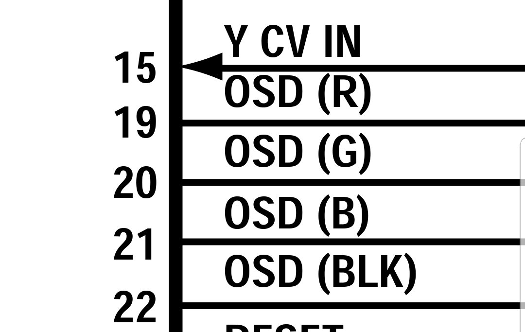
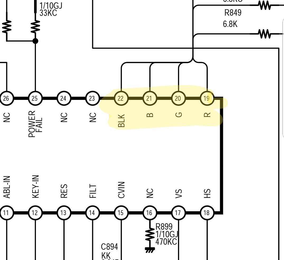
Pins 41, 42, and 43 are your RGB inputs. Take them out of circuit, and tie 75 ohm resistors to ground to match impedence for the 75 ohm load, and add a .1uf coupling cap for black level restoration.
Pin 40 is blanking. Tie pin 40 high to a low voltage source (3v-5v) when you want to enable the RGB input.
If you want me to get REALLY technical...
1) Buy a female SCART socket that's panel mountable. Why? because it's a fucking standard. And even though I roll my owns cables, I like standards. Of course, you can use whatever you want.
2) If you're doing SCART. Wire it up per the SCART standard, I prefer Euro. (Do your 75ohm to ground terminations as well as your .1uF DC caps on the OUTPUTS of the connector to simplify things.)

3) Be a real man and use a template to cut out your SCART connector port.

4) Wire that shit up. Hijack stereo audio and sync from a set of composite inputs. If you're wiring a switch (I use a 6PDT) to switch your OSD lines and RGB inputs, wire that shit up, too.

5) Button it all together.

I've touched on this in passing on various threads when people ask me about doing this. It starts in the service manual. Look up the service manual for the set you'd want to do and review the block diagram, schematics, and chips employed.


 and
and 


