I am looking for some resources on how to build an RGB circuit. I have an old oscilloscope - basically I want to find out how to make a board similar to what mickcris or Voultar made for the pc engine line, as I haven't found an open source version. I can make measurements and do the math, I just don't have a very strong background so any place to start would be great.
Thanks!
RGB attenuation
-
arithmaldor

- Posts: 124
- Joined: Wed Jun 07, 2017 8:39 pm
-
Jumpingmanjim
- Posts: 10
- Joined: Mon Aug 10, 2009 12:58 pm
Re: RGB attenuation
Maybe read the datasheets for the various Texas Instruments Amps? (THS7314,THS7316,THS7374)
-
arithmaldor
- Posts: 124
- Joined: Wed Jun 07, 2017 8:39 pm
Re: RGB attenuation
Ok I'll start there, mainly aiming for 7374. I don't fully understand the diagrams so I'll post questions as I run into them that hopefully someone can answer.

Re: RGB attenuation
RetroRGB has some basic info:
http://retrorgb.com/thsamps.html
Could I ask a favor? Would be cool if you post your results here. I also just ordered some SOIC -> DIP adapters and will soon upgrade my scope, building an RGB bypass for my MD1 and such is something I'd like to try at some point. It doesn't look super complicated (follow the datasheet, hook it up to where the CXA is hooked up on the board, attenuate till you get the right levels, I guess), but would be interesting to see how/if you succeed.
Good luck!
-
arithmaldor
- Posts: 124
- Joined: Wed Jun 07, 2017 8:39 pm
Re: RGB attenuation
Will do!ASDR wrote: Could I ask a favor? Would be cool if you post your results here. I also just ordered some SOIC -> DIP adapters and will soon upgrade my scope, building an RGB bypass for my MD1 and such is something I'd like to try at some point. It doesn't look super complicated (follow the datasheet, hook it up to where the CXA is hooked up on the board, attenuate till you get the right levels, I guess), but would be interesting to see how/if you succeed.
Good luck!
From the 7374 datasheet, the amp has a 6db gain. 6=20*log(x), x=2, so the amp doubles the voltage of whatever you put into it.
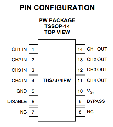
Pin 6 must be ground for the amp to function.
Tie pin 9 high (5V) to turn off the low pass filter.
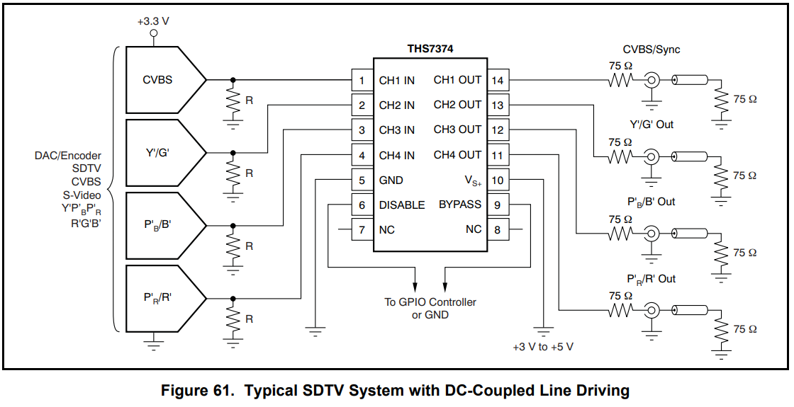
Woowee look at this bad boy. This is DC coupled (not sure what this means but I don't think it's what we want).
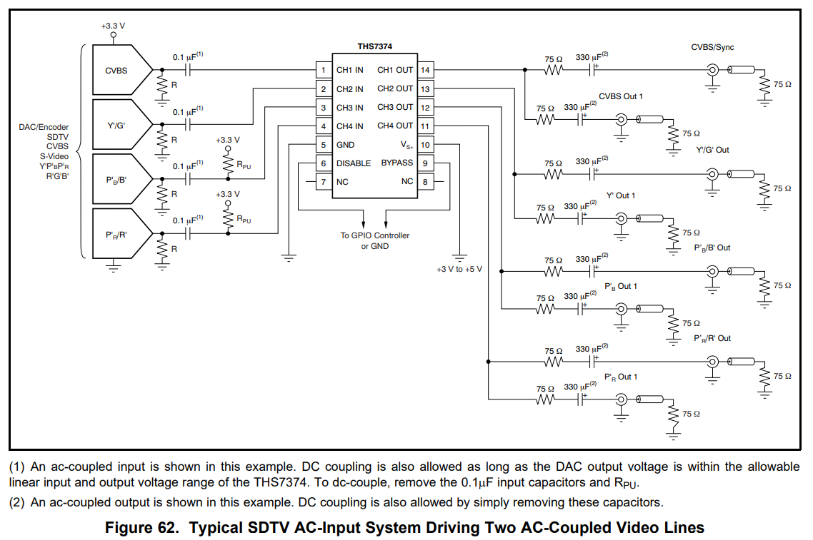
Here is the AC coupled version, although it is configured for dual output:
So, it seems to me like the general idea is to attenuate the signals with resistors going to ground (marked R on the left) before they are boosted with the amp, with a final goal of 0.7Vp-p.
Let's take a look at a board using the THS7374, Borti's board for the SNES:
https://github.com/borti4938/SNES-AddOn ... %20Bypass/
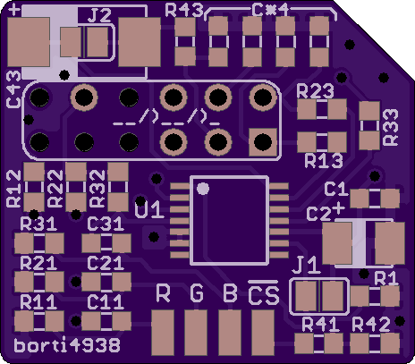
If we follow the Red line, we see that it connects to R11 to ground, with different values for R depending on the SNES model.
The signal then goes through a 0.082μF cap in series. This seems to correlate to the 0.1μF cap in the diagram, but I'm not sure why this is used instead of 0.1. Maybe Borti measured the capacitance of the system there and it was enough to make up the 0.018μF difference.
The signal then goes to the THS7374, with a 5.1MOhm resistor going to ground before this. It looks like this is a pull up resistor, so that if that line is not connected the device still functions and is not floating.
After the amp, the signal goes through a 75 Ohm resistor in series, the connects to the output pin, and also has a 47pF cap to ground.
I'm not sure why there isn't a series cap here like in the diagram, but there isn't one in the first diagram so I'm not sure here.
That's all I've got so far, I will work on this more soon.

Re: RGB attenuation
The last diagram you posted of the 7374 a.c. coupled has the output capacitors facing the wrong way.
-
arithmaldor
- Posts: 124
- Joined: Wed Jun 07, 2017 8:39 pm
Re: RGB attenuation
Oh good spot! I think I remember this being why the cap on the ssds3 was backwards?
-
borti4938
Re: RGB attenuation
Yes, R11, R21 and R32 are for additional attenuation of the outputs - mainly meant for the 1Chip consoles. Common choices are well know; but one has the opportunity to set up each resistor individually.arithmaldor wrote: If we follow the Red line, we see that it connects to R11 to ground, with different values for R depending on the SNES model.
Together with the 5.1Mohm resistor and the 800kohm resistor (inside of the THS7374) this gives a high pass with cut off ~2.8Hz. With 0.1uF you'll have ~2.3Hz, which is a neglectable difference especially if one considers that the 800kohm resistor has a +/-20% tolerance.arithmaldor wrote: The signal then goes through a 0.082μF cap in series. This seems to correlate to the 0.1μF cap in the diagram, but I'm not sure why this is used instead of 0.1. Maybe Borti measured the capacitance of the system there and it was enough to make up the 0.018μF difference.
0.082uF is a rather old choice I took from another project. I'll adapt BOM for 0.1uF.
The 5.1Mohm lifts the signal to a DC @ ~0.7V. After amplification (the THS7374 adds another 150mV level shift) you have ~2V. Assuming the signal has 1.4Vpp and assuming a symmetric probability distribution at 0.7V one get 1.3V low level and 2.7V high level signal. With matching load to output impedance (cable connected) you get 0.65V low level and 1.35V high level (i.e. 0.7Vpp).arithmaldor wrote: The signal then goes to the THS7374, with a 5.1MOhm resistor going to ground before this. It looks like this is a pull up resistor, so that if that line is not connected the device still functions and is not floating.
This is suitable for both PAL cables and NTSC cables by just adapting the output impedance.
(PAL cables have no caps and 75ohm additional loads at receiver side (SCART plug); i.e. one chooses R13, R23 and R33 to 39ohm (or 37.5ohm to be more precise))
75ohms are output impedance.arithmaldor wrote:After the amp, the signal goes through a 75 Ohm resistor in series, the connects to the output pin, and also has a 47pF cap to ground.
I'm not sure why there isn't a series cap here like in the diagram, but there isn't one in the first diagram so I'm not sure here.
That's all I've got so far, I will work on this more soon.
The 47pF caps are decoupling caps while plugging in and out the MultiAV connector. You can also find them on the SNES. I just add them to the layout as they are missing on certain mainboard versions.
- 1Chip-03 lacks of C44 equivalent (C44 next to R44) (C46 on SNES mainboard)
- SNES2 lacks of C41, C42, C43 and C44 equivalents (C44 - C47 previous mainboard models)
-
arithmaldor
- Posts: 124
- Joined: Wed Jun 07, 2017 8:39 pm
Re: RGB attenuation
Wow thanks for the input borti! I realized after my first look that the series capacitors at the end would be in the cable in NTSC consoles.
Re: RGB attenuation
Just out of curiosity were you able to figure this out?