I know default color temp and brightness are off as well. Only natural mode looks right.


I was just gonna do it so it can use sync on composite as well.Syntax wrote:Add a sync stripper if you want but there is no point, the set strips sync inside the jungle.
Stripping sync at the console end of things stoops composite video subcarrier noise from jumping into the RGB lines.
It will do nothing for you at the set end except add delay and cause an off center picture.


Syntax wrote:Make sure the OSD still has it's termination resistors, I couldn't see them on that end of the picture.
Really you should be pulling the leg of the .01caps which is furthest from the jungle, as Tim has already suggested to you..
That way you include everything upstream. Cutting at the OSD chip is a nightmare waiting to happen.
Hey Tim,viletim wrote: I found a low cost TV design that fudges the OSD and SCART input together like this. I think it's the best implementation I've seen. Here's the manual http://etim.net.au/temp/forum/DAEWOO%20 ... V%20SM.pdf (see page 64 of the PDF)
You need to have a resistor in series with the RGB signals. This is because the new termination resistors (75 ohm) in parallel with the RGB video source (75 ohm) makes a load of 37.5 ohms on the RGB input from the OSD signal's point of view. This Daewoo TV puts 150 ohm resistors in series which lifts the load on the OSD signal. Too little or no series resistance = high loading (attenuation) of the OSD, too much series resistance = poor clamp performance. It's a compromise. 150 ohms looks like a good choice to me. The other important part is the RGB OSD signals must each have diodes in series. This way they are effectively out of the circuit when it's off. This prevents loading of the RGB input. An emitter follower + diode OR circuit combines the fast blanking from SCART with the fast blanking of the OSD.
For what ever reason I get a seriously messed up image if I feed it anything ,but csync or luma. Pikkon who has the same set has also experienced this. The only way I have been able to get an image to feed sync through the component y line. I ended up deciding to switch over to csync cables as the only systems i own that can't produce it naturally are my pc duo( i don't want to remove composite), my french n64 and possibly my Phillips Cdi. Retro gaming cables have solutions for the first two. For my cdi I might use a stripper. I would have to build it into a scart to scart connector.Syntax wrote:It can by default though. I dont think there is a consumer set out there that does not accept composite video as sync. Comp video as sync is the standard.
Infact with some LG you must use comp video as sync or else it thinks your csync is luma and changes to svideo.
Some broadcast monitors require csync. That's about it.
Tim,viletim wrote:evilsim,
The TDA9367 has the microcontroller built in. If it's software has not turned on the RGB input (and from your experiments it seems like it has not) then you're out of luck. There's nothing that can be done because there's no way to modify the internal software or intercept the communication between the microcontroller and jungle IC.
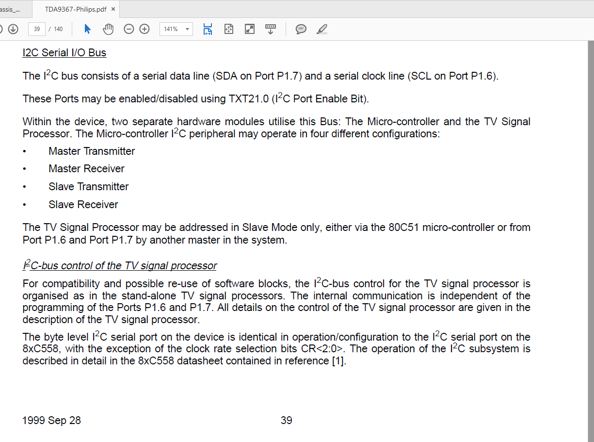

Oh i know that, it was just me letting off steamviletim wrote:TDA is just the prefix for Philips parts. They are not significantly different from other brands. Being able to disable the RGB inputs over the I2C bus is a pretty standard feature to all jungle ICs that have I2C bus support. It's the microcontroller software that actually has control.
It's funny because I've had nothing but success with the TDA's. Easily get RGB running with perfect OSDs on all the ones I've encountered (mostly because of post muxed OSDs)buttersoft wrote:Oh i know that, it was just me letting off steamviletim wrote:TDA is just the prefix for Philips parts. They are not significantly different from other brands. Being able to disable the RGB inputs over the I2C bus is a pretty standard feature to all jungle ICs that have I2C bus support. It's the microcontroller software that actually has control.
Appreciate the other info you've provided lately.
Yeah, it's a total gamble. The only TDA chips I've encountered with I2C have the RGB inputs disabled as well. And in these cases the aus region micom's probably won't have a SCART option, so having the remote to getto the SM might not help.MarkOZLAD wrote:...Let's face it, when grabbing new sets to mod it's a gamble.


Cool, I have 4 of the WEGAs and I'm happy with the components, I really want to make one of my Woody's RGB so it will have an awesome pic that people wouldnt expect.Pikkon wrote:Try and find the schematic for the tv or see what kind of jungle ic it rocks but the sony in the pic can be rgb modded easy.
Wow, nice! I have a few BVMs here that I bet could get a better image with it.Syntax wrote:I've just acquired a 467 tube restorer.
https://youtu.be/Vw7nmuGdDs0
Perfect for those older dull sets.
Keen to have a play with it.


I have the same set, but haven't been able to get RGB video to display. Can you post a picture of how yours is wired up so I can see if it's any different than the way I have mine? Thanks!BobWoggle wrote:Just did a Sony KV20TS29, another super simple one.
On account of there's no CCD board, there's an unoccupied header on the board that connects straight to the RGB, YS, and Earth on the jungle, and another (or rather, unoccupied holes for one) that connects to the standard AV in. Sticking my terminated signals there through their respective caps worked with no hassle.
Mind if i ask how much and where from?Syntax wrote:I've just acquired a 467 tube restorer.
https://youtu.be/Vw7nmuGdDs0
Perfect for those older dull sets.
Keen to have a play with it.
Risky stuff to begin with, and ten times more so for Trinitron tubes, i hear. How do you know they need restoring though?fandangos wrote: Wow, nice! I have a few BVMs here that I bet could get a better image with it.

Could add resistance to the blue line.nakedarthur wrote:Kind of random question for you guys. I noticed the blue was very strong on my KV-27S42, so I went into service menu and started adjusting the RGB Drive and Cuts. I have the Blue drive set all the way down to 0 now, but it seems like it should be at about -2 or -3 to be perfect. Of course I can't go any lower than 0, so I'm wondering if there's anything else I can do? And more generally, do you guys have any easy techniques for adjusting white balance? I was thinking I could raise Red and Green drives to compensate, but wasn't sure if I should open that can of worms yet
meleniumshane90 wrote: I have the same set, but haven't been able to get RGB video to display. Can you post a picture of how yours is wired up so I can see if it's any different than the way I have mine? Thanks!
Thank you for the info. Are you using '104' 0.1uF capacitors?BobWoggle wrote:meleniumshane90 wrote: I have the same set, but haven't been able to get RGB video to display. Can you post a picture of how yours is wired up so I can see if it's any different than the way I have mine? Thanks!
https://imgur.com/a/q3xli I've got 21 to E on cn101, 16 to ys, 15, 11, and 7 to R, G, and B through caps and to 21 through 75 ohm resistors, 20 to VIDEO, and 2 and 6 to V1 R-IN and V1 L-IN on cn401 and cn402.
20 could also probably go to V1 V-IN or V1 Y-IN on cn402.
it's worth noting that cn101 had a header from the factory, I just removed it.
In case it wasn't clear, those numbers are for pins on the SCART. I'm sure you had that figured out but I have no confidenxe in my ability to communicate.
It's a bit of a mess to look at and my color coding is all off but I hope it helps.