Hello. Did you try removing the transistor from the composite video circuit? It was creating interference with my nesrgb mod in a av famicom.heimdalr wrote:i have a few questions in regards to ^
i used to think the 4th mode is to turn off the rgb board, so you could enjoy the av out and rf as supposed to.
if thats not the case, what exactly does the 4th mode?
does the av out work at all with nesrgb on/installed and how much does the composite signal differ from the original?
NESRGB board available now
Re: NESRGB board available now
Re: NESRGB board available now
Hey guys,
having an issue with a top loader im RGB modding, i have everything working now accept the controllers now are acting strange, none of the inputs do anything accept the A button and it acts as if your pressing down and start.
I've used the NES schematics you can find on google and tried to trace the controller ports, as well as using an open controller to make sure the connections were all being made in the controller port and i couldnt find an issue any where.
I've also socketed every chip on the board except the CPU, so unless the CPU could be causing this issue im at a loss for what to do next.
thanks in advance for anyone who takes the time to help
Re: NESRGB board available now
Hi all, I'm having this weird horizontal line ghosting issue with my frontloader NESRGB.
See the ghosting to the right of the dark lines on the doors? It is much more noticeable in other games, like the right of bricks in mario and such, I just don't have good examples right now.

Things I've tried:
See the ghosting to the right of the dark lines on the doors? It is much more noticeable in other games, like the right of bricks in mario and such, I just don't have good examples right now.
Things I've tried:
- Rewiring my RGB port
- Used ribbon cable with ground between every signal
- expensive coaxial mini din 8 to scart
- Tried CSync and composite video sync
- visible on CRT (harder to see but still there) and OSSC capture
- also removed I think it was Q1 transistor?
- using OEM power supply
- System is fully recapped
- definitely not the external cable
-
RottenToTheGore
- Posts: 112
- Joined: Sat Jul 10, 2010 6:07 pm
- Location: Maryland
Re: NESRGB board available now
What if you want 75ohm csync, and you're using an older version of the NESRGB that doesn't have the jumper to switch between TTL/75ohm?leonk wrote:220uF caps already exist on the NESRGB, but it has no effect if you have them in the SCART cable as well. If your SCART cables have resistors as well, then don't follow the recommendations of 75ohm CSYNC!! Use TTL CSYNC on NESRGB. 75ohm csync is only for SCART/RGB cables that have no extra capacitors/resistors.vol.2 wrote:Quick Question... Should I still use the multi-out to SCART cable with the 220 μf 6.3v caps on the RGB outputs? Are the caps necessary, or could it be bad to have them on there in this situation?
I was planning on using the SNES multiout for my NESRGB mod and I was going to buy basically this cable: https://www.retrogamingcables.co.uk/nin ... -wire-cord
If the added output caps are a bad idea, i can just build my own cable.

Re: NESRGB board available now
Nevermind this post, solved my problem
Last edited by unmaker on Fri Jul 14, 2017 10:57 am, edited 1 time in total.

Re: NESRGB board available now
RetroRGB's page suggests NESRGB TTL csync is similar to SNES, so you'd want to add a resistor in the 330-450 Ohm range to the csync line. This is assuming older revisions of NESRGB output in TTL instead of 75 Ohm to begin with. (edit: And it seems to be the case. Mine is NESRGB12, which doesn't have the jumper)RottenToTheGore wrote:
What if you want 75ohm csync, and you're using an older version of the NESRGB that doesn't have the jumper to switch between TTL/75ohm?
-FBX
Re: NESRGB board available now
If you're feeling like experimenting, try connecting each of the RGB signals before its coupling capacitor (yellow thing) on the NESRGB board. It's possible that one of them is bad. It can run without them temporarily, but its not safe to run it like this for long periods of time as the video encoder will overheat.Quantum wrote:Hi all, I'm having this weird horizontal line ghosting issue with my frontloader NESRGB.
See the ghosting to the right of the dark lines on the doors? It is much more noticeable in other games, like the right of bricks in mario and such, I just don't have good examples right now.
Things I've tried:I've been fighting this problem for a really long time and I can't seem to nail it down.
- Rewiring my RGB port
- Used ribbon cable with ground between every signal
- expensive coaxial mini din 8 to scart
- Tried CSync and composite video sync
- visible on CRT (harder to see but still there) and OSSC capture
- also removed I think it was Q1 transistor?
- using OEM power supply
- System is fully recapped
- definitely not the external cable
Re: NESRGB board available now
Hardware version 1.4 (NESRGB14) which is the current one has a 470 ohm resistor in series with a 5V TTL sync signal. The earlier version 1.2 has a 680 ohm resistor in the same position.FBX wrote:RetroRGB's page suggests NESRGB TTL csync is similar to SNES, so you'd want to add a resistor in the 330-450 Ohm range to the csync line. This is assuming older revisions of NESRGB output in TTL instead of 75 Ohm to begin with. (edit: And it seems to be the case. Mine is NESRGB12, which doesn't have the jumper)RottenToTheGore wrote:
What if you want 75ohm csync, and you're using an older version of the NESRGB that doesn't have the jumper to switch between TTL/75ohm?
-FBX
Re: NESRGB board available now
Wait so are you saying my 1.2 NESRGB needs a 680 ohm resistor in the cable, or you actually output 75 Ohm by default in mine and it has the 680 ohm resistor built in?viletim wrote:Hardware version 1.4 (NESRGB14) which is the current one has a 470 ohm resistor in series with a 5V TTL sync signal. The earlier version 1.2 has a 680 ohm resistor in the same position.FBX wrote:RetroRGB's page suggests NESRGB TTL csync is similar to SNES, so you'd want to add a resistor in the 330-450 Ohm range to the csync line. This is assuming older revisions of NESRGB output in TTL instead of 75 Ohm to begin with. (edit: And it seems to be the case. Mine is NESRGB12, which doesn't have the jumper)RottenToTheGore wrote:
What if you want 75ohm csync, and you're using an older version of the NESRGB that doesn't have the jumper to switch between TTL/75ohm?
-FBX
Also, I was under the impression from your web site that the newer 1.4 series uses a jumper on J8 that is open for TTL csync and you can short it for 75 ohm.
-FBX
Re: NESRGB board available now
I'm just describing the circuit. None of my products have every had a 'real' TTL output. That is, one which can source a lot of current an requires a series resistor to work correctly with a 75 ohm video input. There is always a resistor in series on the board itself. The 1.4 design adds a 91 ohm resistor to ground connected by a jumper J8.FBX wrote: Wait so are you saying my 1.2 NESRGB needs a 680 ohm resistor in the cable, or you actually output 75 Ohm by default in mine and it has the 680 ohm resistor built in?
Also, I was under the impression from your web site that the newer 1.4 series uses a jumper on J8 that is open for TTL csync and you can short it for 75 ohm.
-FBX
1/(1/470 + 1/91) = 76.2 = close enough to 75 ohm output impedance.
Re: NESRGB board available now
Okay just bear with me here so I can understand what's actually coming out of each board:viletim wrote:I'm just describing the circuit. None of my products have every had a 'real' TTL output. That is, one which can source a lot of current an requires a series resistor to work correctly with a 75 ohm video input. There is always a resistor in series on the board itself. The 1.4 design adds a 91 ohm resistor to ground connected by a jumper J8.FBX wrote: Wait so are you saying my 1.2 NESRGB needs a 680 ohm resistor in the cable, or you actually output 75 Ohm by default in mine and it has the 680 ohm resistor built in?
Also, I was under the impression from your web site that the newer 1.4 series uses a jumper on J8 that is open for TTL csync and you can short it for 75 ohm.
-FBX
1/(1/470 + 1/91) = 76.2 = close enough to 75 ohm output impedance.
1.4: 1/(1/470 + 1/91) = 76.2 Is this with J8 shorted? If so , whats the level of csync coming out when J8 is left open?
1.2: What's the level of csync coming out of this one?
Again sorry for being dense on this, but I want to be sure I understand the exact spec of each revision's csync output. This is important for making sure we're using the right kind of csync cables.
-FBX
Re: NESRGB board available now
Is it recommended to remove/bypass the NESRGB talatalum capacitors if your using a SCART cable with 220uF aluminum electrolytic capacitors in the SCART plug?viletim wrote:If you're feeling like experimenting, try connecting each of the RGB signals before its coupling capacitor (yellow thing) on the NESRGB board. It's possible that one of them is bad. It can run without them temporarily, but its not safe to run it like this for long periods of time as the video encoder will overheat.
viletim wrote:Hardware version 1.4 (NESRGB14) which is the current one has a 470 ohm resistor in series with a 5V TTL sync signal. The earlier version 1.2 has a 680 ohm resistor in the same position.
Does CSYNC on the NESRGB come from Pin 11 of the BH7236AF?viletim wrote:I'm just describing the circuit. None of my products have every had a 'real' TTL output. That is, one which can source a lot of current an requires a series resistor to work correctly with a 75 ohm video input. There is always a resistor in series on the board itself. The 1.4 design adds a 91 ohm resistor to ground connected by a jumper J8.
1/(1/470 + 1/91) = 76.2 = close enough to 75 ohm output impedance.
Then if I am understanding your posts correctly on the NESRGB 1.4 version it passes through a 470 ohm resistor in series for the TTL CSYNC output, and then optionally through an additional 91ohm resistor to ground for the 75 ohm CSYNC output?
Re: NESRGB board available now
This is about as best as I could piece together from his descriptions. That the J8 jumper adds in another 91 Ohm resistor in the line to bring csync closer to 75 Ohm impedance. If that's the case, then the information on Bob's web page must be wrong because it assumed J8 being open means "TTL csync".Link83 wrote: Then if I am understanding your posts correctly on the NESRGB 1.4 version it passes through a 470 ohm resistor in series for the TTL CSYNC output, and then optionally through an additional 91ohm resistor to ground for the 75 ohm CSYNC output?
All I want is a clear and concise report of the following:
1. What exactly is the final impedance coming out of the csync lead of my 1.2 NESRGB?
2. What exactly is the final impedance coming out of the csync lead of the 1.4 NESRGB with J8 open?
-FBX
Re: NESRGB board available now
Tim, thanks for responding, but I think the specific concern is for people who want to use a SNES RGB SCART cable (that's made to spec) and a SNES Multi-out. In many's people's opinion, for top-loaders or AV Famicoms, that's the ONLY way, as there's no cutting involved; Either connect to the port that's there or buy one of the 3D printed ones that bolts in its place.
In this case, that means people would be using a cable with 220uF caps on the RGB lines and a 330 Ohm resistor on the csync line. Can you explain exactly what people need to do for this cable to work.? Also, please keep in mind that you're not the best at explaining things in laymens terms (no offence), so please try and keep it simple
In this case, that means people would be using a cable with 220uF caps on the RGB lines and a 330 Ohm resistor on the csync line. Can you explain exactly what people need to do for this cable to work.? Also, please keep in mind that you're not the best at explaining things in laymens terms (no offence), so please try and keep it simple

Re: NESRGB board available now
TTL sync seems to work fine for me using a csync super famicom cable from retrogamingcables. The cable on its own measures about 470ohms on the csync line. I'm not certain, but having the extra capacitors doesn't seem to have any effect on the signal
Re: NESRGB board available now
I think you mean resistors, and they do have quite the impact on the signal. They change the impedance which needs to be in a certain range so as not to stress the tolerance levels of the hardware you plug it into.AndehX wrote:TTL sync seems to work fine for me using a csync super famicom cable from retrogamingcables. The cable on its own measures about 470ohms on the csync line. I'm not certain, but having the extra capacitors doesn't seem to have any effect on the signal
Re: NESRGB board available now
No I mean't capacitors. I was talking about the 3 capacitors on the RGB lines in the cable. The NESRGB kit has the capacitors on it already. I was saying that the capacitors in the cable doesn't seem to affect the signal.FBX wrote:I think you mean resistors, and they do have quite the impact on the signal. They change the impedance which needs to be in a certain range so as not to stress the tolerance levels of the hardware you plug it into.AndehX wrote:TTL sync seems to work fine for me using a csync super famicom cable from retrogamingcables. The cable on its own measures about 470ohms on the csync line. I'm not certain, but having the extra capacitors doesn't seem to have any effect on the signal
Re: NESRGB board available now
Ah okay, you were talking about csync and then mentioned caps, so I'm sure you can understand my mixup there.AndehX wrote:No I mean't capacitors. I was talking about the 3 capacitors on the RGB lines in the cable. The NESRGB kit has the capacitors on it already. I was saying that the capacitors in the cable doesn't seem to affect the signal.FBX wrote:I think you mean resistors, and they do have quite the impact on the signal. They change the impedance which needs to be in a certain range so as not to stress the tolerance levels of the hardware you plug it into.AndehX wrote:TTL sync seems to work fine for me using a csync super famicom cable from retrogamingcables. The cable on its own measures about 470ohms on the csync line. I'm not certain, but having the extra capacitors doesn't seem to have any effect on the signal
Re: NESRGB board available now
FBX,
Here's the output circuit.
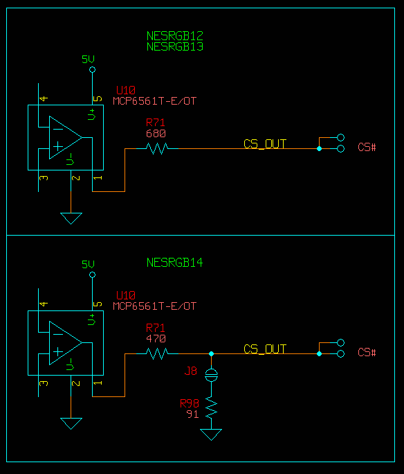
U10 is the comparator connected to the buffered video signal from the PPU in order to extract the sync. The output is a push/pull to each rail. The output impedance of that device is probably something like 10-30 ohms.
An additional series resistor in the cable of 330 ohms (making the worse case total [30+680+330 = 1.04k]) should still be reliable. If the series resistor in the cable is 470 ohms, it may be on marginal side with the older NESRGB 1.2 and 1.3 hardware. This is in theory only.
The unrelated question regarding whether its to have capacitors in series with each video signal (R, G ,B) if these capacitor already exist on board. I think it's fine. Placing two capacitors in series does reduce the capacitance, but it doesn't cause any trouble in practice.
I'm going to do some proper SCART cable testing soon. I already have some cables from Retrogamingcables.co.uk
Here's the output circuit.
U10 is the comparator connected to the buffered video signal from the PPU in order to extract the sync. The output is a push/pull to each rail. The output impedance of that device is probably something like 10-30 ohms.
An additional series resistor in the cable of 330 ohms (making the worse case total [30+680+330 = 1.04k]) should still be reliable. If the series resistor in the cable is 470 ohms, it may be on marginal side with the older NESRGB 1.2 and 1.3 hardware. This is in theory only.
The unrelated question regarding whether its to have capacitors in series with each video signal (R, G ,B) if these capacitor already exist on board. I think it's fine. Placing two capacitors in series does reduce the capacitance, but it doesn't cause any trouble in practice.
I'm going to do some proper SCART cable testing soon. I already have some cables from Retrogamingcables.co.uk
Re: NESRGB board available now
I don't know how the formulas are calculated, so maybe you could help me out on this:
Earlier you stated:
1/(1/470 + 1/91) = 76.2 = close enough to 75 ohm output impedance.
So what I'm asking since I'm not an electrical engineer is the logical progression:
If 1/(1/470 + 1/91) = 76.2 (J8 closed)
1/(1/470) = ?? (as in J8 is open)
1/(1/680) = ?? (my NESRGB12)
And again my apologies for not having a clue here, but the above is what I'm trying to figure out.
-FBX
Re: NESRGB board available now
Any luck resolving this? I also saw your reddit thread where you mentioned replacing the 7805 with the 1.5A kind, did that have any noticeable difference?Quantum wrote:Hi all, I'm having this weird horizontal line ghosting issue with my frontloader NESRGB.
See the ghosting to the right of the dark lines on the doors? It is much more noticeable in other games, like the right of bricks in mario and such, I just don't have good examples right now.
Things I've tried:I've been fighting this problem for a really long time and I can't seem to nail it down.
- Rewiring my RGB port
- Used ribbon cable with ground between every signal
- expensive coaxial mini din 8 to scart
- Tried CSync and composite video sync
- visible on CRT (harder to see but still there) and OSSC capture
- also removed I think it was Q1 transistor?
- using OEM power supply
- System is fully recapped
- definitely not the external cable
I've finished this mod last night and have found that I also have this issue.

Zoomed in with contrast increased:

It's unnoticeable on my PVM-20M4U because of scanlines but it is noticeable on my HDTV and capture card. It personally doesn't bother me but I'm trying to sell this and can't sell it in this condition.
Re: NESRGB board available now
Did you try a different pair of RGB SCART cables? I saw this before she using cheap cables that were not correctly made.
Another idea is the power supply. Are you using original nintendo do power supply or some cheap switching power supply that adds noise ??
Another idea is the power supply. Are you using original nintendo do power supply or some cheap switching power supply that adds noise ??
Re: NESRGB board available now
Thank you for the suggestions but I don't think the issue has to do with either of those. I have 2 OEM NES adapters and there is no noticeable difference between the two. I also don't have any other device in my chain. I have only 1 pair of RGB SCART cables but I also have HD Retrovision cables which also yields the same result.leonk wrote:Did you try a different pair of RGB SCART cables? I saw this before she using cheap cables that were not correctly made.
Another idea is the power supply. Are you using original nintendo do power supply or some cheap switching power supply that adds noise ??
-
Einzelherz

- Posts: 1279
- Joined: Wed Apr 09, 2014 2:09 am
Re: NESRGB board available now
Is your audio running separately or in the same cable?
Re: NESRGB board available now
post pics of install job.
Re: NESRGB board available now
@ Shartqueefa, your pics look like a different type of noise than the Garfield picture. In that pic, they looks to be a ghosting effect from dark-to-light contrast, while yours looks to be an overall noise pattern in the background.
I guess the ultimate way to figure out what's causing it is to have two NESRGB kits and two NES consoles, where one is confirmed fine in comparison to the messed up one. You'd then swap the kits to see if the noise effect swaps. If it doesn't, then it's very likely the console. If it does, then it's either the NESRGB board or the install job being defective. Unfortunately such a test would be a MPITA.
I guess the ultimate way to figure out what's causing it is to have two NESRGB kits and two NES consoles, where one is confirmed fine in comparison to the messed up one. You'd then swap the kits to see if the noise effect swaps. If it doesn't, then it's very likely the console. If it does, then it's either the NESRGB board or the install job being defective. Unfortunately such a test would be a MPITA.
-
mikejmoffitt

- Posts: 629
- Joined: Fri Jan 08, 2016 7:26 am
- Location: Tokyo, Japan
Re: NESRGB board available now
If you've got caps in the cable, try without them. The NESRGB already has 220uF caps in the output chain. This looks like a DC offset from a line carrying into H-blank, which is slightly affecting your clamping values.
Both the Garfield and Super Mario Bros pictures look this way.
This could also be a capture card issue with the NES's picture timing in particular. You can try shifting the image to the right, or playing with clamping controls.
Both the Garfield and Super Mario Bros pictures look this way.
This could also be a capture card issue with the NES's picture timing in particular. You can try shifting the image to the right, or playing with clamping controls.

Re: NESRGB board available now
Same cable. I have everything going out to a OEM SNES multi out.Einzelherz wrote:Is your audio running separately or in the same cable?
My first NESRGB install so it's a bit sloppy:leonk wrote:post pics of install job.
http://imgur.com/a/g8Yf1
The reason I suspect it's a similar issue to that of Quantum's Garfield pic is because he/she mentions in their post that "It is much more noticeable in other games, like the right of bricks in mario and such". The noise that I'm seeing is not a constant background noise. The lines only appear when say the bricks in Mario are in the scene. Here are some more pics demonstrating where the lines are visible:FBX wrote:@ Shartqueefa, your pics look like a different type of noise than the Garfield picture. In that pic, they looks to be a ghosting effect from dark-to-light contrast, while yours looks to be an overall noise pattern in the background.
I guess the ultimate way to figure out what's causing it is to have two NESRGB kits and two NES consoles, where one is confirmed fine in comparison to the messed up one. You'd then swap the kits to see if the noise effect swaps. If it doesn't, then it's very likely the console. If it does, then it's either the NESRGB board or the install job being defective. Unfortunately such a test would be a MPITA.
http://imgur.com/a/tybUG
Unfortunately Mario is the only game I have atm so I can't see how other game look.
If it comes to that, I will give it a shot. I have another front loader that I want to mod but I need to wait for the kits to restock. It definitely will be a MPITA but I'd like to narrow down the problem.
Haven't gone around to checking if I have any caps in my cable but I don't think that's the issue. I say this because I can see the lines with HD Retrovision component cables and with composite cables on my HDTV. The only display I have to check S-Video is my PVM. The lines are incredibly difficult to make out on a PVM but I do think I see them so this is a problem on all outputs.mikejmoffitt wrote:If you've got caps in the cable, try without them. The NESRGB already has 220uF caps in the output chain. This looks like a DC offset from a line carrying into H-blank, which is slightly affecting your clamping values.
Both the Garfield and Super Mario Bros pictures look this way.
This could also be a capture card issue with the NES's picture timing in particular. You can try shifting the image to the right, or playing with clamping controls.
I do think the issue has to do with either one of these mistakes I made during this install:
1. On the external +5 regulator board, I had Vin and +5V connected backwards. I had+5V going into Vin and Vin going into +5V. It caused this loud audio humming and a barely visible, thick, white transparent line scrolling from the top to the bottom of the screen repeatedly. I had the console running for anywhere between 15 to 20 minutes like this before I decided to check all the connections and noticed the mistake. Maybe in the time I had the NES running with these connected incorrectly I damaged something?
2.When replacing the caps on the power supply/modulator board, there was a capacitor lead that was also connected to the end of a SMD cap. When desoldering that lead it also sucked off the metalic enclosure (I don't know what you call it) of the SMD rendering it useless. I couldn't find a schematic for this PCB that would tell me the value of this SMD in order to replace it so I removed another SMD cap (which I later lost) that I thought was of the same value and measured it at ~183pF. My multimeter is off by about 30pF so I ordered 150pF caps and put them both in. The new SMD caps measured at ~180pF with my multimeter so this most likely is not the issue. However I feel it's worth mentioning since I'm at a loss at this point and I'm usually clueless when it comes to troubleshooting stuff like this.
The SMD cap I initially damaged when removing the through-hole cap was the one located at the top right:
http://imgur.com/a/slzHJ
This shows the new ones I put in.
Thank you all for your help.
Re: NESRGB board available now
Doesn't look like a horrible install.
The only thing I would have done differently is skip the external power regulator. Not needed. Top loader kits don't even come with it.
The only thing I would have done differently is skip the external power regulator. Not needed. Top loader kits don't even come with it.
Re: NESRGB board available now
Wouldn't that cause overheating? At least that's what I see in Viletim's instructions. Anyway I removed the external power regulator earlier today in the hopes that it might resolve my issue but it made no difference. I also tried removing the jumper at J8 to allow TTL sync just in case my cable had caps in it. No difference. I'm at a complete loss at this point.leonk wrote:Doesn't look like a horrible install.
The only thing I would have done differently is skip the external power regulator. Not needed. Top loader kits don't even come with it.
Also I saw you made a post a few pages back:
I've been using the 5V from the NESRGB for my multi out, should I get it from elsewhere like the 5V from the voltage regulator?leonk wrote:Just because you got a 5V pad on the NESRGB, doesn't mean it's a good choice for LED, 5V multiAV pin, whatever you need 5V for. Learned this the hard way a long time ago. You will fry a transistor on the NESRGB. Get 5V from elsewhere!
Need to dig up the old email from Tim abou this.