After reading through all the info in this thread, I took on a Toshiba 27A32 as a weekend project. Here is the jungle IC from the service manual for this set:

Pins 20, 21, 22 for R, G, B, (isolated from existing circuit, on a switch, 75ohm terminated, 0.1uf ceramics, fed from a scart connector) and 19 for blanking (switched tie to pin 2 for 5v). I started off using the svideo luma for sync, but just got a rolling image. This TV has some input sensing to activate the svideo over composite as they share audio inputs. Plugging any svideo cable in would trigger the switch and sync the image. Neat! But, the image was dark. Between Brightness in the picture menu, and RGB Contrast in the service menu, I got it looking better, but not great.
The next day I was fiddling with it and realized that the TV tuner input also has a dark filter (to keep the snow from burning your eyes / phosphor?) when there is no solid signal. In fact, (almost) ALL the inputs were very dark until a signal is detected. The only input without this is the "Color Stream" input. Turns out that's Toshiba's fancy name for the YPbPr composite RCAs, so I moved sync to Y.
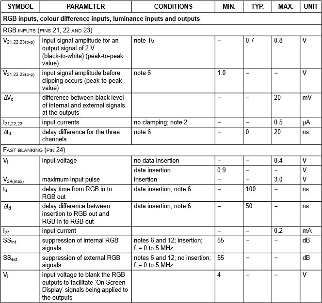
This seemed to work great! The picture was bright and colorful. So bright that when the screen flashed white, the set would power off. Before remembering that I jacked the settings up the day before (reverting these seems to have solved the power-off problem) I found a Japanese data sheet for the IC:

Apparently he blanking pin doesn't expect more than 3.3v, but others in this thread have fed 5v in the same situation without issues. I had also tried adding a 10k pot to ground (the original blanking signal has a 2.2kohm) which only seemed to cause more problems, so it was removed. Anyway, I didn't really take pictures of the install, but here is the end result:


Now I also have an ESA ET427E set, which is apparently a variation of a SYLVANIA SST4274S with this m61271m8-058fp IC

I can't find this datasheet, so maybe someone can shed some light on this chip. Is seems the OSD functions are built right in, but maybe some unused pins (34, 35, 36?) are an RGB input. That would be cool.


