TV RGB mod thread

Re: TV RGB mod thread
Well, he's right, a decent PVM is going to be sharper since it's going to have a higher TVL count and use better phosphors. That doesn't mean that an RGB-modded CRT isn't good too, it's just not as high quality of a device...

Re: TV RGB mod thread
Wondering if it makes sense to RGB mod one of these: kv-32hs510
I have this TV, and while it does a great job with 480p material, as I understand it, it automatically treats 240p content as 480i. (I'm still not 100% sure about this, but I have read about it on other forums, and there is a youtube game channel that mentions it as well)
The TV already has a component in but, as I mentioned, it displays 240p as 480i. I think the component in goes to a digital processing unit of some kind that converts non-native resolutions to their nearest neighbor or something.
In terms of do-ability, I have the service manual. I can do electronics work, and I am experienced with soldering and PCBS. I actually build circuits at work sometimes, and I have experience working on audio equipment like amplifiers, etc, but I have never worked on a TV, so I would be a bit new to all of that.
What I am hoping for, is that someone can tell me if this would be worth it. Is it even doable at all? Am I correct in thinking that this massive 1080i CRT from the last few years of SONY EDTV/HDTVs probably has a higher than average vertical line count?
-
KnuckleheadFlow

- Posts: 111
- Joined: Tue Jul 26, 2016 1:40 pm
Re: TV RGB mod thread
I'm almost sure that an EDTV will have a single chip jungle IC/MCU combination, therefore no RGB lines in between to tap into. If so, the only way to get RGB going would be to drive the electron guns directly. Not nearly as simple from what I understand.
Re: TV RGB mod thread
Hi guys got a question that hopefully someone with more experience could answer. I modded 2 TVs so far one was an old 90's RCA tube and had only one composite input, I hooked up the sync to the luma pin on the jungle IC and it handle's any sync I've thrown at it so far. My question is about the second TV I modded, a newer sharp 2006 tube with 3 composite, one Svideo and one component input I used the composite the first composite pin for sync and attempted to do a dpdt switch to use luma on the svideo in case I needed it. The compsosite video input works but when I try using the luma pin it doesn't work. Was wondering if maybe the TV might have an enable pin on the Svideo port that tells it when a cable is plugged in and allowing sync to be fed to luma pin. By the way the svideo and composite video input share the video 1 input, that led me to believe there has to be an enable pin. Anyone else encountered this?
-
KnuckleheadFlow
- Posts: 111
- Joined: Tue Jul 26, 2016 1:40 pm
Re: TV RGB mod thread
Oh, no question. I've never seen one in person but I'm sure I'd still love a P/BVM (or any other pro RGB)... if it was big enough, not used up and priced right. And available.Guspaz wrote:Well, he's right, a decent PVM is going to be sharper since it's going to have a higher TVL count and use better phosphors. That doesn't mean that an RGB-modded CRT isn't good too, it's just not as high quality of a device...
A couple of months back, I actually did find a PVM for a price I was willing to pay, one of these. It doesn't power on, so it's in the projects queue.
-
suprcrackers

- Posts: 55
- Joined: Fri Apr 15, 2016 9:31 pm
Re: TV RGB mod thread
I agree. My problem this whole time hasn't been that I disagree with the fact that PVM/BVMs are better. It's just saying it so flippantly without explaining the obvious size and price difference which obviously should come into play, that feels wrong.
-
thebeautifulones

- Posts: 41
- Joined: Thu Jul 03, 2014 6:03 am
Re: TV RGB mod thread
I'm planning on modding a Panasonic ct-27xf11cs.
This is the IC I'm looking at http://pdf.datasheetcatalog.com/datashe ... N5307K.pdf
Can someone tell me if this seems right?
1. lift the OSD RGB pins (22, 23, 24)
2. solder scart socket RGB to 75ohm resistors and ground the resistors, to ie. pin 27
3. solder 0.1uf caps between the resistors and the IC's RGB pins (edit: it looks like I may need to attenuate 0.7 to 0.5?)
4. connect Ys input (pin 21) to a 5v source, ie. pin 37
5. solder c-sync from scart socket to composite video input of TV
I'm especially wondering about step 4. Is that the blanking pin?
-
KnuckleheadFlow
- Posts: 111
- Joined: Tue Jul 26, 2016 1:40 pm
Re: TV RGB mod thread
Yes those are the pins and yes, it looks like a 0.5 Vpp RGB signal is needed. Now, I wrote a bunch of stuff about attenuators a bit ago but it could be as simple as using a resistor in series with the RGB input. I was planning experimenting using a few pots (100 Ohm?) once it's time to mod my own Panasonic (ct-27xf34c) and read up on video attentuation.
And from the electrical characteristics on that pdf's page 9 (page 231 in the scanned original I guess) it'd appear that Ys (pin 21, blanking) only needs 1 V. Not sure what 5 V would do but I'd look into using a linear regulator (like this one, costs about $3 http://www.ti.com/product/lp3879/description) if there isn't a 1 V source handy.
And from the electrical characteristics on that pdf's page 9 (page 231 in the scanned original I guess) it'd appear that Ys (pin 21, blanking) only needs 1 V. Not sure what 5 V would do but I'd look into using a linear regulator (like this one, costs about $3 http://www.ti.com/product/lp3879/description) if there isn't a 1 V source handy.
-
KnuckleheadFlow
- Posts: 111
- Joined: Tue Jul 26, 2016 1:40 pm
Re: TV RGB mod thread
Wow, do I feel stupid. If your TV's jungle IC needs it, going from 0.7 Vpp to 0.5 Vpp is dead simple. Looking for video attenuation examples I realized that superguns with SCART connectors need to do this to drop the ~3 Vpp JAMMA RGB to 0.7 Vpp.
I had a look at this guy's supergun and long story short, a 30 Ω resistor in series with the RGB input before the 75 Ω terminations will make a voltage divider that'll attenuate the typical console's 0.7 Vpp to 0.5 Vpp.
My reasoning being that in the above supergun we've got:
For our purposes we can ignore the AD8073 amplifiers (probably) since that's accounting for the RGB being split to his encoder IC (AD725) and SCART connector. All that matters is the voltage divider. A regular resistive voltage divider is:
So with that supergun, R1 is 180 Ω (+ optional 250 Ω pot) and R2 is 75Ω to go from 2.3 Vpp (I guess that's the typical JAMMA RGB signal and the pots are there for stronger boards sending 3 V?) to 0.7 Vpp. Our R2 will also be 75 Ω and we want to go from 0.7 V in to 0.5 V out so...
Add a pot along with that 30 Ω resistor in case you get something with stronger signals and Bob's your uncle. It's really simple and I'm surprised it took me this long to figure out.
I had a look at this guy's supergun and long story short, a 30 Ω resistor in series with the RGB input before the 75 Ω terminations will make a voltage divider that'll attenuate the typical console's 0.7 Vpp to 0.5 Vpp.
My reasoning being that in the above supergun we've got:
Code: Select all
JAMMA RGB in (3 Vpp) ---[R1 180Ω]---[optional 250Ω pot]--- --- AD8073 amps then SCART RGB out (0.7Vpp)
                                                          |
                                                          |--- AD725 encoder IC
                                                          |
                                                       [R2 75Ω]
                                                          |
                                                          |
                                                         GND
Code: Select all
V in ---[R1]--- --- V out
               |
              [R2]
               |
              GND

with
V out = R2/R1+R2 * V in
Code: Select all
0.5 V = (75Ω / xΩ + 75Ω) * 0.7 V
...
x = 30Ω
Re: TV RGB mod thread
Hey guys, trying to do my third mod for a friend. His jungle ic generates osd internally but there is a set of pins 46 47 48 that are unused. They are labeled rgb/yuv insert couuld these be used and what would be my blanking pin pin 49? 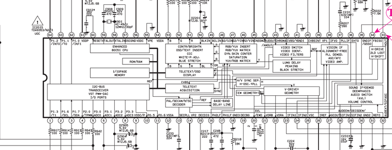

Last edited by cruzlink2 on Wed Nov 09, 2016 11:39 pm, edited 2 times in total.
-
mikejmoffitt

- Posts: 629
- Joined: Fri Jan 08, 2016 7:26 am
- Location: Tokyo, Japan
Re: TV RGB mod thread
I have a chance to get a 36" Trinitron, from the same vintage as my KV-27S42. Think I should pick it up? It's free.

-
KnuckleheadFlow
- Posts: 111
- Joined: Tue Jul 26, 2016 1:40 pm
Re: TV RGB mod thread
Ha you honestly think anyone in this thread would tell you no?
Only reasons I see not to is if I knew I couldn't mod it, it had some flaw not worth fixing like screen burn, or I didn't have the room. Worst case scenario you gotta ditch a big TV.
Only reasons I see not to is if I knew I couldn't mod it, it had some flaw not worth fixing like screen burn, or I didn't have the room. Worst case scenario you gotta ditch a big TV.
-
thebeautifulones
- Posts: 41
- Joined: Thu Jul 03, 2014 6:03 am
Re: TV RGB mod thread
Thanks a lot for the info, Knucklehead. Going to order the resistors.
Re: TV RGB mod thread
it's a really, really big monitor. maybe a little too big for 240p in my opinion. it's also going to be super heavy to move around. not the kind of thing you would want to lift solo. for me, i wouldn't want anything bigger than 32" in a CRT. 25" is probably my sweet spot.mikejmoffitt wrote:I have a chance to get a 36" Trinitron, from the same vintage as my KV-27S42. Think I should pick it up? It's free.
i guess you gotta ask yourself if it's something you would use, and if it's worth the trouble.
Re: TV RGB mod thread
I must be invisible in this thread, 3 post so far and 0 reply.
-
KnuckleheadFlow
- Posts: 111
- Joined: Tue Jul 26, 2016 1:40 pm
Re: TV RGB mod thread
Aw c'mon don't be like that. If you're not getting a reply, it's probably because nobody knows a good enough answer. Or they're slightly neurotic and think they've been posting too much, worried people will think they're trying pretend they know more than they really do when they're talking out of their ass.
The pic you posted is small and there's details missing, pin 50 is blanking but who knows at what voltage. You could connect it to a variable voltage PS, start at 1V and stop when you get a black screen. And sometimes unconnected pins are enabled, sometimes they're not. Only one way to find out. If they're disabled, well it might be possible to dump the firmware, find a way to enable them and reflash it, but at that point I'd think it's just time to get a different TV.
The pic you posted is small and there's details missing, pin 50 is blanking but who knows at what voltage. You could connect it to a variable voltage PS, start at 1V and stop when you get a black screen. And sometimes unconnected pins are enabled, sometimes they're not. Only one way to find out. If they're disabled, well it might be possible to dump the firmware, find a way to enable them and reflash it, but at that point I'd think it's just time to get a different TV.
Re: TV RGB mod thread
Thanks for the reply knuckle here is a link to a better picture http://imgur.com/mxdFLSm .
-
KnuckleheadFlow
- Posts: 111
- Joined: Tue Jul 26, 2016 1:40 pm
Re: TV RGB mod thread


Still needs a little tweaking but the PoC works. Unlike the PiP.
Well, it said BLK but the 300 V further up tells me you should stay away from that pin. I don't see a blanking pin as usual, but the fact it says "RGB/YUV insert" sounds hopeful. I'd poke around, maybe it switches automatically? Or with an I2C signal? Dunno enough about this to give a proper answer.cruzlink2 wrote:Thanks for the reply knuckle here is a link to a better picture http://imgur.com/mxdFLSm .
-
KnuckleheadFlow
- Posts: 111
- Joined: Tue Jul 26, 2016 1:40 pm
Re: TV RGB mod thread
I don't think I made it clear enough, the setup above has the external RGB mod while keeping the OSD RGB.
I can now see the volume level and adjust the picture with RGB as the reference. It makes it almost look like it came with RGB from the factory. This also has the benefit of getting rid of the big ass 4P2T switch, just a small on/off for the blanking.
I can now see the volume level and adjust the picture with RGB as the reference. It makes it almost look like it came with RGB from the factory. This also has the benefit of getting rid of the big ass 4P2T switch, just a small on/off for the blanking.
Re: TV RGB mod thread
That's awesome! Is this potential doable for every osd-hack RGB?KnuckleheadFlow wrote:I don't think I made it clear enough, the setup above has the external RGB mod while keeping the OSD RGB.
I can now see the volume level and adjust the picture with RGB as the reference. It makes it almost look like it came with RGB from the factory. This also has the benefit of getting rid of the big ass 4P2T switch, just a small on/off for the blanking.
-
KnuckleheadFlow
- Posts: 111
- Joined: Tue Jul 26, 2016 1:40 pm
Re: TV RGB mod thread
Yup, it'll work with any TV that works with this mod. It essentially replaces the 4P2T switch with a Linear Technology LT1675. I've got it using the OSD blanking signal to very rapidly switch between the two RGB sources; "pixel switching" as I found out.
The best part is that it can be made for about $10. In addition to the LT1675, it uses two other ICs, an on/off switch, six capacitors and nine resistors.
I had the thing designed more than a month ago and I was trying to figure out how to make PCBs since (along with fucking around with my new SNES and Genesis flashcarts and the OSSC I'm now assembling). After a weekend spent trying to make the toner transfer method work without success, I decided that the plain transparancies/photoresist/UV exposure method can't be that bad. Well, my photoresist STILL hasn't arrived so I got a prototyping board with surface mount pads fine enough to rig up a prototype.

That's it in the middle, flapping in the breeze, supported by wires lol. I'm glad the picture's blurry because frankly it looks like a mess. There're some details to work out, like why the image is a little bit darker/dimmer than usual, but it works! Once I can actually print my PCB, make some minor changes and eliminate the shitty board layout as a problem and move some components around, I'll put the circuit up on github or something.
The best part is that it can be made for about $10. In addition to the LT1675, it uses two other ICs, an on/off switch, six capacitors and nine resistors.
I had the thing designed more than a month ago and I was trying to figure out how to make PCBs since (along with fucking around with my new SNES and Genesis flashcarts and the OSSC I'm now assembling). After a weekend spent trying to make the toner transfer method work without success, I decided that the plain transparancies/photoresist/UV exposure method can't be that bad. Well, my photoresist STILL hasn't arrived so I got a prototyping board with surface mount pads fine enough to rig up a prototype.
That's it in the middle, flapping in the breeze, supported by wires lol. I'm glad the picture's blurry because frankly it looks like a mess. There're some details to work out, like why the image is a little bit darker/dimmer than usual, but it works! Once I can actually print my PCB, make some minor changes and eliminate the shitty board layout as a problem and move some components around, I'll put the circuit up on github or something.
Re: TV RGB mod thread
Yea Knuckle I thought the same thing about the blanking pin not really being a regular blanking pin. In this diagram you can see that the OSD is done internally inside the jungle IC, so therefore no need for external blanking. I am starting to think that the rgb points are just an extra input that might have been used in a more expensive model, I read the user manual and it points to unused ports that are for a optional component input/scart in the European model. So maybe this input does not need any blanking I think because it's an actual input and not an OSD/RGB in for the menu. I will give a shot to just plugging in the pins and seeing what I get. Thanks for your replies again.
Re: TV RGB mod thread
That's seriously cool.KnuckleheadFlow wrote:Yup, it'll work with any TV that works with this mod. It essentially replaces the 4P2T switch with a Linear Technology LT1675. I've got it using the OSD blanking signal to very rapidly switch between the two RGB sources; "pixel switching" as I found out.
The best part is that it can be made for about $10. In addition to the LT1675, it uses two other ICs, an on/off switch, six capacitors and nine resistors.
I had the thing designed more than a month ago and I was trying to figure out how to make PCBs since (along with fucking around with my new SNES and Genesis flashcarts and the OSSC I'm now assembling). After a weekend spent trying to make the toner transfer method work without success, I decided that the plain transparancies/photoresist/UV exposure method can't be that bad. Well, my photoresist STILL hasn't arrived so I got a prototyping board with surface mount pads fine enough to rig up a prototype.
That's it in the middle, flapping in the breeze, supported by wires lol. I'm glad the picture's blurry because frankly it looks like a mess. There're some details to work out, like why the image is a little bit darker/dimmer than usual, but it works! Once I can actually print my PCB, make some minor changes and eliminate the shitty board layout as a problem and move some components around, I'll put the circuit up on github or something.
I love stuff like this. I will try to get your design into a set if I can.
Have you ever seen this blog? This guy is driving guns to make a vector machine. Wonder how repeatable this stuff is on better sets?
https://spritesmods.com/?art=bwidow_fpga&page=1
-
KnuckleheadFlow
- Posts: 111
- Joined: Tue Jul 26, 2016 1:40 pm
Re: TV RGB mod thread
Oh yeah, I've seen it. One of my pie in the sky, future mods is "big screen Vectrex".
-
buttersoft

- Posts: 383
- Joined: Sun Jul 24, 2016 7:49 am
Re: TV RGB mod thread
How will the TV know it's receiving RGB through those pins, and to display it? I understand you're seeing internal blanking elsewhere, and the set is capable of it, but I'm not sure that equates to it working automatically. I have a Samsung PoS that when set to the auxiliary AV channel looks blue until fed sync, whereupon it blanks itself. So if you get the RGB to display, but something else is displaying behind it, or even just the blue, you might try that. I couldn't find a way to turn my RGB inputs on though, as I think it was I2C controlled. I'd be interested to hear how you get on as it might help me get furthercruzlink2 wrote:In this diagram you can see that the OSD is done internally inside the jungle IC, so therefore no need for external blanking. I am starting to think that the rgb points are just an extra input that might have been used in a more expensive model, I read the user manual and it points to unused ports that are for a optional component input/scart in the European model. So maybe this input does not need any blanking I think because it's an actual input and not an OSD/RGB in for the menu. I will give a shot to just plugging in the pins and seeing what I get.
EDIT: I think my problem might be that without the remote I can't get to the primary AV channel, only to the secondary one, which won't display RGB.
-
buttersoft
- Posts: 383
- Joined: Sun Jul 24, 2016 7:49 am
Re: TV RGB mod thread
In fact, I'd love some advice for modding a Samsung HiTron TV-488. I'm not having any luck finding the service manual, but it uses this Philips IC (TDA8841) - https://my.mixtape.moe/hiflqk.pdf.
(This post was a mess,so I've tried to clean it up from here)
What I'm doing -
Feeding PSOne Luma to the secondary AV line - shows up as B&W
Feeding 5V to pin 26 of the jungle chip - blanks the display
Feeding RGB to pins 23 thru 26 after that - does nothing, no image appears at all.
However, feeding amped RGB onto the output pins of the jungle chip instead (pins 20 thru 22, nominally 2Vp-p) shows a stable picture, but it's not a great picture. It starts very bright with retrace lines, and then fades away to a very low brightness level over a few minutes. Disconnecting and reconnecting things sometimes brings the image back up to retrace brightness.
I'd really prefer to use the chip's RGB inputs, if anyone can help...
EDIT: ok, so looking at the PCB, the Micom feeds the neckboard directly, it doesn't feed the jungle chip. Its outputs meet up with the jungle IC outputs and thence to the neckboard. There are components missing on this revision that would allow it to feed the RGB inputs of the jungle IC, as well as/instead of the outputs - it looks like all you'd have to do is swap over one diode for each colour to fork to the inputs instead. If i did swap those... what would happen? I wonder if there's a way to turn on the RGB inputs? or am I using the wrong blanking pin?
EDIT: Ok, the Service manual is here - https://my.mixtape.moe/zwwyvm.pdf Taken me months to find it, and finally, once i post here, i clued into something. My has the TDA8841 one chip, NOT the 8842 as shown. And the Micom is the non-TTx version, on the very last page. There might be a different manual for the Australian version, with the 8841 shown. Maybe it doesn't have the RGB inputs enabled?
it should work on the secondary AV channel? I can't get to the primary one (rear of the set) without the remote...unless pulsing something into pin 41 of the Micom will do something... anyone know how to do that? +5V logic level?
EDIT: No dice. I don't think this jungle IC takes RGB in, though the schematics from philips say it does. Or if it does, it's being blocked over the I2C bus. That's why the Micom feeds it's own RGB to the neckboard. I should test the levels of that, i suppose.
Last edited by buttersoft on Sun Nov 27, 2016 12:57 am, edited 8 times in total.
Re: TV RGB mod thread
Cool Knuckle!
I will try this when I get some spare time and see if it works with my JVC.
My original post here: http://shmups.system11.org/viewtopic.ph ... 7#p1211477
I will try this when I get some spare time and see if it works with my JVC.
My original post here: http://shmups.system11.org/viewtopic.ph ... 7#p1211477
KnuckleheadFlow wrote:Wow, do I feel stupid. If your TV's jungle IC needs it, going from 0.7 Vpp to 0.5 Vpp is dead simple. Looking for video attenuation examples I realized that superguns with SCART connectors need to do this to drop the ~3 Vpp JAMMA RGB to 0.7 Vpp.
I had a look at this guy's supergun and long story short, a 30 Ω resistor in series with the RGB input before the 75 Ω terminations will make a voltage divider that'll attenuate the typical console's 0.7 Vpp to 0.5 Vpp.
My reasoning being that in the above supergun we've got:For our purposes we can ignore the AD8073 amplifiers (probably) since that's accounting for the RGB being split to his encoder IC (AD725) and SCART connector. All that matters is the voltage divider. A regular resistive voltage divider is:Code: Select all
JAMMA RGB in (3 Vpp) ---[R1 180Ω]---[optional 250Ω pot]--- --- AD8073 amps then SCART RGB out (0.7Vpp) | |--- AD725 encoder IC | [R2 75Ω] | | GNDSo with that supergun, R1 is 180 Ω (+ optional 250 Ω pot) and R2 is 75Ω to go from 2.3 Vpp (I guess that's the typical JAMMA RGB signal and the pots are there for stronger boards sending 3 V?) to 0.7 Vpp. Our R2 will also be 75 Ω and we want to go from 0.7 V in to 0.5 V out so...Code: Select all
V in ---[R1]--- --- V out | [R2] | GND with V out = R2/R1+R2 * V inAdd a pot along with that 30 Ω resistor in case you get something with stronger signals and Bob's your uncle. It's really simple and I'm surprised it took me this long to figure out.Code: Select all
0.5 V = (75Ω / xΩ + 75Ω) * 0.7 V
...
x = 30Ω
-
suprcrackers
- Posts: 55
- Joined: Fri Apr 15, 2016 9:31 pm
Re: TV RGB mod thread
Knuckle that is very, very cool. The only reason I didn't reply is sometimes these forums tell me when new posts have been made to this thread and a lot of times it doesn't.
-
mikejmoffitt
- Posts: 629
- Joined: Fri Jan 08, 2016 7:26 am
- Location: Tokyo, Japan
Re: TV RGB mod thread
Buttersoft, your experience resembles my first attempt on a 20" trinitron TV - fading from too bright, briefly "just right", then going darker. I did not ever properly solve it, so if you figure it out, I'd be interested in what you did.
Re: TV RGB mod thread
Trying to RGB mod my 32" Panasonic TV, model CT-32G13W. I removed the OSD lines and tapped in my RGB and pulled blank high to 5v. I hooked up my Neo Geo MVS and used the composite in for sync. Here is what I got right off.
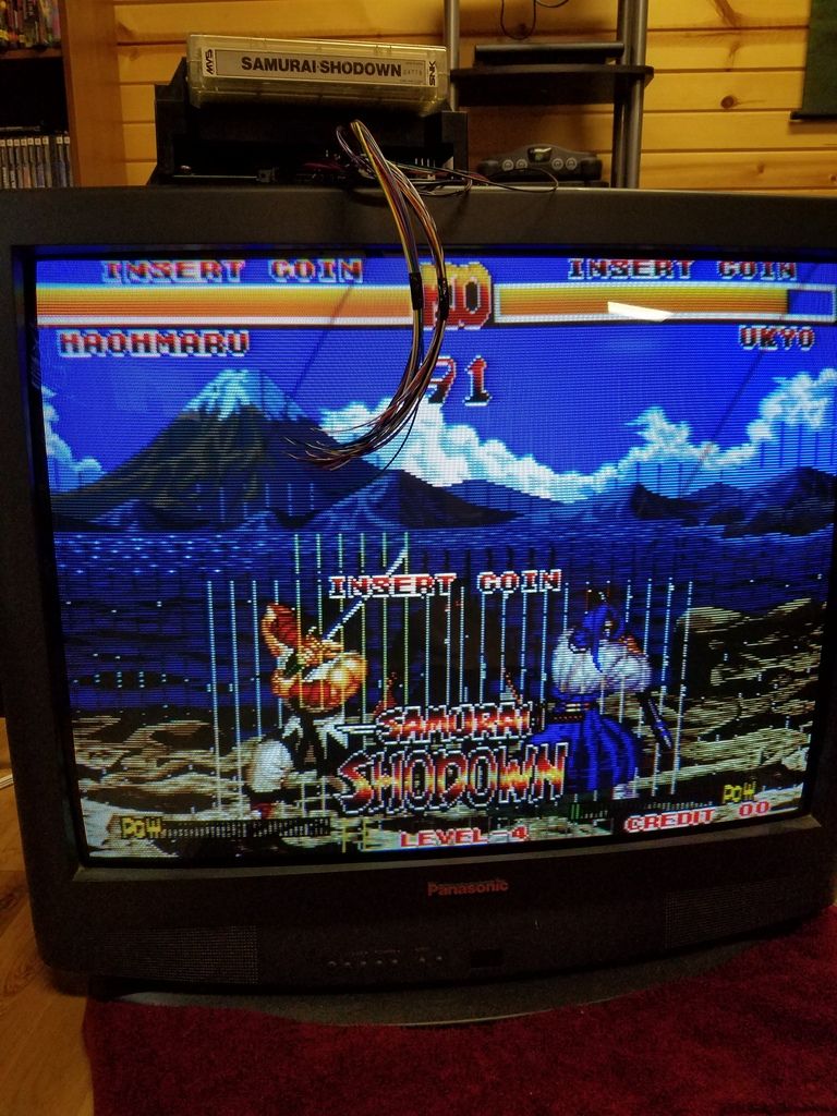
Just need to figure out how to get those bars out of it. This is the only thing I have to test with at the moment. I don't have any other consoles with RGB at the moment, more to come of course! So what is left to do to get this working good?
Just need to figure out how to get those bars out of it. This is the only thing I have to test with at the moment. I don't have any other consoles with RGB at the moment, more to come of course! So what is left to do to get this working good?