
A general purpose AV driver amplifier created by Tim Worthington! 4 channels video, 2 channels audio, 1 channel sync. It works well in the PC Engine and in other applications too.
Site: http://etim.net.au/av-driver/

Initial Documentation (subject to change)
Application on PC Engine / TG16 / Duo ConsolesConnections
O1 = video output channel 1
I1 = video input channel 1
O2 = video output channel 2
I2 = video input channel 2
O3 = video output channel 3
I3 = video input channel 3
O4 = video output channel 4
I4 = video input channel 4
OT = sync output (TTL or 75 ohm depending on J2)
IT = sync input (TTL or PCE depending on J1)
OR = audio output right
OL = audio output left
IR = audio input right
IL = audio input left
VCC = 5V or 3.3V (best performance at 5V)
There are lots of ground points for convenience.
Each video amplifier has a set of jumpers for setting the gain (0-4) and another for setting the attenuator (5-7). There is also a bias setting which is common to all video amplifiers. Gain and attenuation must be set the same to every amplifier. The bias setting must match the amplifier gain setting.
Gain is variable from 1.0 to 4.1 in 0.1 increments. Gain is set in binary with jumpers 0-4 representing bits 0-4. For example, to set the gain to 1.6 (good for the PC Engine), you would close jumpers 1 and 2.
There is an input attenuator on the input which can be set to three valid states.
5 = closed, 6 = open, 7 = open. no attenuation.
5 = open, 6 = closed, 7 = open. input /3
5 = open, 6 = open, 7 = closed. input /6
Attenuation is necessary if the input signal is > 1.4Vp-p
Jumpers J1 and J2 relate to the sync amplifier. J1 should be open for the PC Engine and closed otherwise. This is a special feature for the small sync signal on the PC engine. J2 should be closed for a 75 ohm sync output (normal) or open for a TTL sync output (such as an arcade monitor). If the sync buffer circuit is not used J1 and J2 should be left open to save power.
Audio is set by the level control potentiometer. The audio amplifier gain is fixed at 6.
Note: Never solder on the component side of the board!
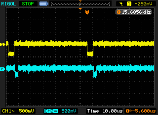
Fix for PC Engine / TG16 / Duo 'Jail Bar' Video NoiseThe Hu6260 RGB video output is 0.864 Vp-p. To bring it close to 1.4 Vp-p the gain needs to be set to 1.6. To do this close the '1' and '2' jumpers for each channel and bias. Remember that the bias should always set the same as the gain (it's not an independent control). If you find the 1.6 gain too dim, also close jumper '0' for each channel and bias for a 1.7 gain.
For CSYNC amplification for XRGB or TV monitor usage, leave J1 open, and close J2. (Hu6260 pin 44 or Expansion connector pin A3)
http://etim.net.au/av-driver/pcebars/
AvailabilityGeneral Procedure
1. Disassemble the console and find the HuC6260 chip on the motherboard.
2.Find the power supply decoupling capacitors close by.
3.Work out which are for the digital side and which are for the analog side. Usually there are three or four on each side. They can easily be grouped together by their proximity and the large power tracks on the PCB which they connect to. It doesn't matter which group is digital and which is analog.
4.Pick one from each group (it doesn't really matter which one exactly) and use the continuity check feature of your multimeter to confirm that the capacitors are indeed for power supply decoupling. Both caps are connected between 5V and ground.
5.Remove two caps from the motherboard (if necessary) and replace with the 4.7 uF replacement caps.
The AV-DRIVER is available for purchase on Tim's shop - http://etim.net.au/shop/shop.php?crn=211
Edit: Now Available! (6/10/16)


