OSSC (DIY video digitizer & scandoubler)

Re: DIY video digitizer & scandoubler
No need to convert RGB SCART to Component for use with this board it accepts RGB natively.
OSSC Forums - http://www.videogameperfection.com/forums
Please check the Wiki before posting about Morph, OSSC, XRGB Mini or XRGB3 - http://junkerhq.net/xrgb/index.php/Main_Page
Please check the Wiki before posting about Morph, OSSC, XRGB Mini or XRGB3 - http://junkerhq.net/xrgb/index.php/Main_Page
-
meneerbeer
- Posts: 50
- Joined: Thu Mar 26, 2015 9:14 am
Re: DIY video digitizer & scandoubler
How did you get the EP4CE15 into KiCad? Are there any quick tricks to it? I am kind of reluctant to fill in 144 pins by hand. With my own board I was lucky someone else already made a symbol and package for Eagle, but I want to be able to move to different FPGAs some time.

Re: DIY video digitizer & scandoubler
I used this component generator to generate the symbol and connection info, which is probably a faster way than Kicad's builtin editor. For the footprint, I just modified a generic QFP-144 footprint to include a bottom ground pad.meneerbeer wrote:How did you get the EP4CE15 into KiCad? Are there any quick tricks to it? I am kind of reluctant to fill in 144 pins by hand. With my own board I was lucky someone else already made a symbol and package for Eagle, but I want to be able to move to different FPGAs some time.
I've almost assembled the first board, so I'll know in a few days if everything went fine...
-
meneerbeer
- Posts: 50
- Joined: Thu Mar 26, 2015 9:14 am
Re: DIY video digitizer & scandoubler
I guess that is not too bad. I see that Altera provides .txt files with device pinout, so with some processing it should be possible to import that into that generator.marqs wrote:I used this component generator to generate the symbol and connection info, which is probably a faster way than Kicad's builtin editor. For the footprint, I just modified a generic QFP-144 footprint to include a bottom ground pad.meneerbeer wrote:How did you get the EP4CE15 into KiCad? Are there any quick tricks to it? I am kind of reluctant to fill in 144 pins by hand. With my own board I was lucky someone else already made a symbol and package for Eagle, but I want to be able to move to different FPGAs some time.
Good luck! I hope it works.I've almost assembled the first board, so I'll know in a few days if everything went fine...
One thing I have been wondering about: linedoubling 240p results in an output image with 526 lines, I think. How is compatibility with TVs for that? I guess linedoubled 480i fits the best in the 480 spec, if not perfectly? Are there 858 samples per line?
Re: DIY video digitizer & scandoubler
Regarding the HDMI issue, I came across this recently..
http://www.misco.co.uk/product/200886/L ... -Converter
The availability of that converter allows you to go with DVI out and still give people an option of HDMI + Audio if needed. Not ideal, but better than paying an obscene amount for the HDMI license.
http://www.misco.co.uk/product/200886/L ... -Converter
The availability of that converter allows you to go with DVI out and still give people an option of HDMI + Audio if needed. Not ideal, but better than paying an obscene amount for the HDMI license.
OSSC Forums - http://www.videogameperfection.com/forums
Please check the Wiki before posting about Morph, OSSC, XRGB Mini or XRGB3 - http://junkerhq.net/xrgb/index.php/Main_Page
Please check the Wiki before posting about Morph, OSSC, XRGB Mini or XRGB3 - http://junkerhq.net/xrgb/index.php/Main_Page
Re: DIY video digitizer & scandoubler
Yes, "240p" is typically 262 or 263 lines (or apparently 264 with Neo-Geo), so linedoubled output is +-1 line off the 525-line standard. I haven't yet encountered a display where that would be an issue - for example Panasonics seem to accept +-2 line deviation. 480i linedoubled is exactly 525 lines, so that's most compatible as you said. I'm using 858 samples per line with SCART and YPbPr inputs for linedoubled 240p/480i and 480p, and 800 samples with VGA input for 640x480. The samplerate is fairly easy to change, so it's possible to provide tweaking options for those whose displays have some tolerance. For example, I think the standard 800 samples per line would not be most optimal for Dreamcast's VGA.meneerbeer wrote:One thing I have been wondering about: linedoubling 240p results in an output image with 526 lines, I think. How is compatibility with TVs for that? I guess linedoubled 480i fits the best in the 480 spec, if not perfectly? Are there 858 samples per line?
Re: DIY video digitizer & scandoubler
Yeah, that'd be a good option for those who don't route audio directly to an AV receiver. It's too bad that DisplayPort is such a rarity among TVsBuckoA51 wrote:Regarding the HDMI issue, I came across this recently..
http://www.misco.co.uk/product/200886/L ... -Converter
The availability of that converter allows you to go with DVI out and still give people an option of HDMI + Audio if needed. Not ideal, but better than paying an obscene amount for the HDMI license.
-
meneerbeer
- Posts: 50
- Joined: Thu Mar 26, 2015 9:14 am
Re: DIY video digitizer & scandoubler
That is correct. Dreamcast outputs at 480p timings, so there are 858 pixels (or something close to that, have not checked) per line. Only about 640 pixels contain video data. Most monitors do not like 480p over VGA and they cram the picture with part of the borders into a 640x480 area.marqs wrote:meneerbeer wrote:The samplerate is fairly easy to change, so it's possible to provide tweaking options for those whose displays have some tolerance. For example, I think the standard 800 samples per line would not be most optimal for Dreamcast's VGA.
Re: DIY video digitizer & scandoubler
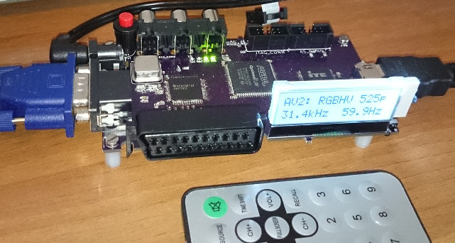
The first test board is now complete, and the blocks seem to be mostly working. Unfortunately, it seems that analog side of TVP7002 got somehow damaged during soldering as blue channel is completely missing and there's some noise. Otherwise, sync is stable and the board was even able to output 1080p coming from PC via VGA. I'll need to look more closely into that TVP7002 or perhaps build another board with more care. Then it's possible to say if everything really works or not... Anyway, below is a photo of the complete board for those interested to see it how it looks. I'm currently using a cheapo remote for control but the system can be programmed to support any remote using NEC protocol.

Re: DIY video digitizer & scandoubler
Neat! The red button cycles output res or input select?
 | My games - http://www.emphatic.se | (Click) I have YEN stickers for sale
RegalSin wrote:Street Fighters. We need to aviod them when we activate time accellerator.
Re: DIY video digitizer & scandoubler
It's the power button. All other controls are handled via remote.emphatic wrote:Neat! The red button cycles output res or input select?
-
invzim

- Posts: 45
- Joined: Tue Jul 24, 2007 8:40 am
- Location: https://irkenlabs.com/
- Contact:
Re: DIY video digitizer & scandoubler
Neato! What do you do for control, softcpu or a MCU?

Re: DIY video digitizer & scandoubler
looks hot!
Re: DIY video digitizer & scandoubler
Absolutely stoked for this.
OSSC Forums - http://www.videogameperfection.com/forums
Please check the Wiki before posting about Morph, OSSC, XRGB Mini or XRGB3 - http://junkerhq.net/xrgb/index.php/Main_Page
Please check the Wiki before posting about Morph, OSSC, XRGB Mini or XRGB3 - http://junkerhq.net/xrgb/index.php/Main_Page
Re: DIY video digitizer & scandoubler
I'm using Nios II softcpu as it's sufficient for handling the control tasks. The only downside is that it eats away the block memory of the FPGA which could be used elsewhere, and there's not enough free pins on the QFP package to use external memory.invzim wrote:Neato! What do you do for control, softcpu or a MCU?
Re: DIY video digitizer & scandoubler
Hi!
I followed this thread, found it quite interesting. Does this chip have internal memory?
What is the state of this?
I followed this thread, found it quite interesting. Does this chip have internal memory?
What is the state of this?
Re: DIY video digitizer & scandoubler
The FPGA has a small amount of volatile memory for line buffers, logic, software etc. There's also a flash chip on-board, which contains the FPGA bitstream (firmware) which is automatically loaded when the system is powered on. The flash could also be used for storing various user settings.Marmes wrote:Hi!
I followed this thread, found it quite interesting. Does this chip have internal memory?
What is the state of this?
As for the state, I'm still debugging the single-board prototype. The manufacturing quality of the PCBs was worse than in the first prototype so I've had difficulties getting the large, thin-leg ICs soldered reliably on the board. I've also been busy with other stuff during the last few weeks so I haven't had that much time for this project.
-
FinalBaton

- Posts: 4461
- Joined: Sun Mar 08, 2015 10:38 pm
- Location: Québec City
Re: DIY video digitizer & scandoubler
just added this thread to my bookmarks. Very interesting project! 
Would be interested in purchasing one, too.
Would be interested in purchasing one, too.
-FM Synth & Black Metal-
Re: DIY video digitizer & scandoubler
I finally found out the root cause of the noise issue on the PCB. KiCad's automatic ground plane generation extended the plane too near to a signal trace, ignoring design rule constraints. This resulted to a short circuit on the manufactured PCB, effectively grounding one of the HDMI data wires. I managed to cut the short with a knife, and the board is now working without any major issues  . I still need to design a slightly revised PCB as there's also a number of small improvements needed, but next I can concentrate on putting the firrmware and features together.
I'm planning to buy a SC-512N1 capture card, so soon I should be able to upload some videos showing the video output quality of the board.
I'm planning to buy a SC-512N1 capture card, so soon I should be able to upload some videos showing the video output quality of the board.
-
Konsolkongen

- Posts: 2318
- Joined: Fri May 16, 2008 8:28 pm
- Location: Denmark
Re: DIY video digitizer & scandoubler
Great that you worked out that bug. Looking forward to seeing more screenshots of this thing in action!
Re: DIY video digitizer & scandoubler
Exciting times ahead! 
OSSC Forums - http://www.videogameperfection.com/forums
Please check the Wiki before posting about Morph, OSSC, XRGB Mini or XRGB3 - http://junkerhq.net/xrgb/index.php/Main_Page
Please check the Wiki before posting about Morph, OSSC, XRGB Mini or XRGB3 - http://junkerhq.net/xrgb/index.php/Main_Page
Re: DIY video digitizer & scandoubler
i have been contemplating something like this, but have no CPLD experience
my thoughts were slightly different, but so close it would be better to brainstorm
my thoughts
240P input
line trippled
optional blank 3rd line (scanline mode)
2 line buffers spec pixel width for 720P 60
the process.....
input V-sync
buffer 1 loads at 15K input scan line 1
at H-sync input switches to buffer 2
output active
out reads buffer 1 at 45K scan rate
at input Hsync buffers swap
total lag is 1 line (1 input line)
Re: DIY video digitizer & scandoubler
That's pretty much how I've implemented the linetriple mode. A few tricks are also needed in order to display 4:3 image in 1280x720 area, but they are relatively easy and do not require extra line buffers.thesteve wrote:i have been contemplating something like this, but have no CPLD experience
my thoughts were slightly different, but so close it would be better to brainstorm
my thoughts
240P input
line trippled
optional blank 3rd line (scanline mode)
2 line buffers spec pixel width for 720P 60
the process.....
input V-sync
buffer 1 loads at 15K input scan line 1
at H-sync input switches to buffer 2
output active
out reads buffer 1 at 45K scan rate
at input Hsync buffers swap
total lag is 1 line (1 input line)
Re: DIY video digitizer & scandoubler
i didnt see you had a line triple mode
anyway 4:3 is just a null count at the start and end of each output scan
so whats the status?
i was hoping to implement something like this into internal system mods, possibly with component output instead of HDMI
anyway 4:3 is just a null count at the start and end of each output scan
so whats the status?
i was hoping to implement something like this into internal system mods, possibly with component output instead of HDMI
Re: DIY video digitizer & scandoubler
Yes - output pixel clock is set 3*(4/3) = 4 times the input sampling clock in the most straightforward setup (960 samples of active video each line) so that start and end can be filled with black pixels while keeping horizontal scan rate 3x the input.thesteve wrote:i didnt see you had a line triple mode
anyway 4:3 is just a null count at the start and end of each output scan
There's info on the status on some earlier posts - currently I'm working on the PCB, and then there's also work to do on verifying/improving compatibility with some systems.thesteve wrote:so whats the status?
Wouldn't VGA be a better choice for an analog output?thesteve wrote:i was hoping to implement something like this into internal system mods, possibly with component output instead of HDMI
-
bobrocks95

- Posts: 3473
- Joined: Mon Apr 30, 2012 2:27 am
- Location: Kentucky
Re: DIY video digitizer & scandoubler
I for one am hoping it's possible for both a VGA input and output, with HDMI (well, DVI considering those licensing fees) output as well. Switching to analog output for interlaced stuff would be a nice option to have over the quick deinterlacing.
PS1 Disc-Based Game ID BIOS patch for MemCard Pro and SD2PSX automatic VMC switching.
Re: DIY video digitizer & scandoubler
VGA is a good output, but component makes is compatible with more TVsmarqs wrote: Wouldn't VGA be a better choice for an analog output?
the biggest need for this is that 240P is unsupported or badly supported by too much of the newer sets
current scalars wait 2X V-Sync before they even try to form an image and use a MPG algorithm to produce it
this looks ok on a natural looking image, but on high contrast pixel art (games) it causes artifacts and image softness
-
HDgaming42

- Posts: 331
- Joined: Wed Jul 15, 2009 3:16 am
- Location: Canada
Re: DIY video digitizer & scandoubler
I think it would. Why compromise quality at this stage of the game? Although VGA input is getting rarer, it is far more likely your TV will mangle a VGA input less than a component one.marqs wrote:Wouldn't VGA be a better choice for an analog output?
This isn't exactly a mass-market device where you need to cater to the lowest common denominator. To consider analog output at all, I'd throw my vote behind VGA as opposed to component. My two cents...

Re: DIY video digitizer & scandoubler
VGA is better yes, but proper VGA>anything conversion can be a bitch (you need the right transcoder/converter and additional power slot).
Strikers1945guy wrote:"Do we....eat chicken balls?!"