NESRGB board available now

The place for all discussion on gaming hardware
User avatar
lettuce
Posts: 1336
Joined: Wed Jun 22, 2011 7:10 pm
Location: Bedfordshire, England.

Re: NESRGB board available now

Post by lettuce »

darcagn wrote:It should be the 12K and 20K resistors, why not just use a multimeter and test continuity from pins 1 and 2 on the CPU to be sure?
Yeah spot on, it is indeed the 12k and 20k resistors!

Is it recommended to solder to the left side of the resistors (12k and 20K) or to the actual legs (1 & 2) of the CPU chip?, im guessing the left leg of the resistors would be cleaner

Image
User avatar
darcagn
Posts: 607
Joined: Tue Mar 04, 2008 3:26 pm
Contact:

Re: NESRGB board available now

Post by darcagn »

It doesn't matter from a technical standpoint but it's better to solder to the resistors because they are less likely to be damaged by heat and if they were, you could easily replace them compared to a CPU, and they are easier/cleaner to solder to anyway.
User avatar
lettuce
Posts: 1336
Joined: Wed Jun 22, 2011 7:10 pm
Location: Bedfordshire, England.

Re: NESRGB board available now

Post by lettuce »

darcagn wrote:It doesn't matter from a technical standpoint but it's better to solder to the resistors because they are less likely to be damaged by heat and if they were, you could easily replace them compared to a CPU, and they are easier/cleaner to solder to anyway.
Thats a valid point!

Has anyone done the stereo mod in conjunction with the NESRGB audio?.

I was just wondering how this works with the NESRGB, as it only has the one connection for the audio output (pad 'O'). On a standard AV Famicom you would.....

1. Connected wires to CPU pins 1 & 2
2. Run those wires to the negative leg of a pair of 1uf caps
3. Connect the positive leg of the caps to either a potentiometer or switch.
4. Then run a pair of wires from the connections on the potentiometer or switch (where the caps are solder to) to 2 phone sockets for the audio.


But where the NESRGB is involved your unable to do step 4 as there is only the 1 audio output wire for the NESRGB. How do you carry out this mod if your using the audio from the NESRGB?
User avatar
darcagn
Posts: 607
Joined: Tue Mar 04, 2008 3:26 pm
Contact:

Re: NESRGB board available now

Post by darcagn »

I am personally not a fan of doing the "stereo mod" to begin with, because that's not the way the system was meant to be heard and frankly I think it sounds bad. That having been said, why would you even use phono sockets on an AV Famicom? Just cut the traces on the board connecting the stock audio to the L-audio and R-audio pins, and then cut the trace connecting the L-audio and R-audio pins together, and then connect the outputs to the two pins so that you can get stereo audio out of the multiout connector. And then on top of that, the circuit you just described would mix the audio levels unevenly and doesn't account for expansion audio so FDS games and games that had extra audio chips would have portions of its soundtrack completely missing.
User avatar
lettuce
Posts: 1336
Joined: Wed Jun 22, 2011 7:10 pm
Location: Bedfordshire, England.

Re: NESRGB board available now

Post by lettuce »

darcagn wrote:I am personally not a fan of doing the "stereo mod" to begin with, because that's not the way the system was meant to be heard and frankly I think it sounds bad. That having been said, why would you even use phono sockets on an AV Famicom? Just cut the traces on the board connecting the stock audio to the L-audio and R-audio pins, and then cut the trace connecting the L-audio and R-audio pins together, and then connect the outputs to the two pins so that you can get stereo audio out of the multiout connector. And then on top of that, the circuit you just described would mix the audio levels unevenly and doesn't account for expansion audio so FDS games and games that had extra audio chips would have portions of its soundtrack completely missing.
I was just watching GameTechUS video on the mod.....

https://www.youtube.com/watch?v=uG8387V ... e=youtu.be

he had a Top Loader, so that why i refereed to the phono sockets.

Yeah thats what im saying, if you have the NESRGB and am wanting to use the audio from that, grabbing the audio from cpu pins 1&2 and the connection it up to pads 'A' & 'B' on the NESRGB then you only have 1 wire out from the NESRGB (pad 'O'), so im guessing you cant do the 'stereo' mod if your using the NESRGB audio as your need to wires to connect to L-audio and R-audio on the multiout socket
User avatar
CkRtech
Posts: 668
Joined: Mon Aug 27, 2012 9:30 pm
Location: Seattle, WA

Re: NESRGB board available now

Post by CkRtech »

lettuce wrote:he had a Top Loader, so that why i refereed to the phono sockets.
Hmm. If you will allow me to ignore whatever wikipedia says about all of this, I say 1/4" jacks = "phono", 1/8" jacks = "mini-phono", and RCA jacks = "RCA".

Just my two cents.
User avatar
darcagn
Posts: 607
Joined: Tue Mar 04, 2008 3:26 pm
Contact:

Re: NESRGB board available now

Post by darcagn »

lettuce wrote:I was just watching GameTechUS video on the mod.....

https://www.youtube.com/watch?v=uG8387V ... e=youtu.be

he had a Top Loader, so that why i refereed to the phono sockets.
But the Top Loader and the AV Famicom are completely different in regards to audio so it's completely irrelevant. The Top Loader doesn't have a multiout, it just has RF output, so of course you have to add phono sockets. And their audio circuits are completely different.
CkRtech wrote:Hmm. If you will allow me to ignore whatever wikipedia says about all of this, I say 1/4" jacks = "phono", 1/8" jacks = "mini-phono", and RCA jacks = "RCA".

Just my two cents.
On what basis do you say this? You have it backwards.

RCA connectors are also called phono connectors because they are the connectors RCA used in their phonographs.

1/4" and 1/8" jacks are called phone connectors (phone, not phono) because they were used in telephone switchboards.
User avatar
CkRtech
Posts: 668
Joined: Mon Aug 27, 2012 9:30 pm
Location: Seattle, WA

Re: NESRGB board available now

Post by CkRtech »

<shrug> I don't really use "phono" despite my write-up (in favor of simply "quarter inch" and mini") so I guess it is an honest mistake. The term is too ambiguous. For instance if you bought a new receiver and asked if it had a phono input, the answer would most likely be "no" despite the fact there are RCA plugs all over it since "phono" is also a term used for a specific input on a receiver that has a built-in pre-amp for turntables.

Heh. Apologies to all for the slight de-rail on the NESRGB thread. :mrgreen:
User avatar
Ed Oscuro
Posts: 18654
Joined: Thu Dec 08, 2005 4:13 pm
Location: uoıʇɐɹnƃıɟuoɔ ɯǝʇsʎs

Re: NESRGB board available now

Post by Ed Oscuro »

CrKtech's right though, "phone" corrupted to "phono" in common use pretty widely in the 20th century. Calling RCA jacks "phono" is what I find confusing. But hey, the more you know *rainbow*
User avatar
lettuce
Posts: 1336
Joined: Wed Jun 22, 2011 7:10 pm
Location: Bedfordshire, England.

Re: NESRGB board available now

Post by lettuce »

darcagn wrote:
lettuce wrote:I was just watching GameTechUS video on the mod.....

https://www.youtube.com/watch?v=uG8387V ... e=youtu.be

he had a Top Loader, so that why i refereed to the phono sockets.
But the Top Loader and the AV Famicom are completely different in regards to audio so it's completely irrelevant. The Top Loader doesn't have a multiout, it just has RF output, so of course you have to add phono sockets. And their audio circuits are completely different.
Ok let's forget about the whole phono situation for the moment, of course you wouldn't need phono sockets where the AV Famicom is concerned, but you still need 2 audio output wires (fake left and right). What I was original asking is can the fake stereo mod be carried out of a system that has the NESRGB fitted and is using the NESRGB for the audio as your only have the one audio output wire coming from the NESRGB?

Also in what way are the audio circuits different from the Top Loader to the AV Famicom please?.....or though I'm wanting to use the NESRGB audio anyways, but would seem it's not possible to do the stereo mod if using the NESRGB audio
User avatar
darcagn
Posts: 607
Joined: Tue Mar 04, 2008 3:26 pm
Contact:

Re: NESRGB board available now

Post by darcagn »

lettuce wrote:Ok let's forget about the whole phono situation for the moment, of course you wouldn't need phono sockets where the AV Famicom is concerned, but you still need 2 audio output wires (fake left and right). What I was original asking is can the fake stereo mod be carried out of a system that has the NESRGB fitted and is using the NESRGB for the audio as your only have the one audio output wire coming from the NESRGB?
I don't understand your logic here. When you do the stereo mod that you described, you are bypassing the NES mono circuit and creating your own, no? You are not "using" the NES's circuit in any way because it is a mono audio circuit. It is of no use to you. So what exactly are you trying to accomplish with the NESRGB mono circuit?
lettuce wrote:Also in what way are the audio circuits different from the Top Loader to the AV Famicom please?
The Famicom series are built differently because they have to account for expansion audio. Your proposed stereo audio circuit doesn't account for expansion audio at all, so that is your concern. You have three sets of audio to worry about (CPU pin 1, CPU pin 2, and the cart pin). You can't just send one pin to the left and one pin to the right because you still have more audio. You'll need to design a different circuit to compensate for having another set of audio.
User avatar
lettuce
Posts: 1336
Joined: Wed Jun 22, 2011 7:10 pm
Location: Bedfordshire, England.

Re: NESRGB board available now

Post by lettuce »

darcagn wrote:The Famicom series are built differently because they have to account for expansion audio. Your proposed stereo audio circuit doesn't account for expansion audio at all, so that is your concern. You have three sets of audio to worry about (CPU pin 1, CPU pin 2, and the cart pin). You can't just send one pin to the left and one pin to the right because you still have more audio. You'll need to design a different circuit to compensate for having another set of audio.
Guess its not so straight forward then.

I might have to hit GameTechUS up, as his done the mod on a AV Famicom with NESRGB.....

https://www.youtube.com/watch?v=DGH87k-bej8

He'll be able to tell me what need to be done i guess
User avatar
lettuce
Posts: 1336
Joined: Wed Jun 22, 2011 7:10 pm
Location: Bedfordshire, England.

Re: NESRGB board available now

Post by lettuce »

Is it usual for the audio from the NESRGB to be of a lower volume than that from the actual AV Famicom??. This is the first AV i have done and cant remember (or though to be fair didnt really test) the front loaders being being much different in audio level from the audio from the NESRGB??

Also i have NOT cut the trace for pins 46 or 45 from the cart slot connector and have the expansion audio working 100% fine, no interference or hissing, or though i HAVE cut the traces going to the 2 audio channels pins on the multiout socket. Have had the volume turned up to 50 on my TV which is WAY louder than i'd ever have it and all is fine.

Whats the idea behind cutting the traces between pins 45 and 46 on the cart slot connector, is it just to eliminate any chances of interference??
ms06fz
Posts: 103
Joined: Mon Apr 14, 2014 8:48 pm

Re: NESRGB board available now

Post by ms06fz »

Famicom expansion audio isn't just an audio line coming off the cart. Game audio from the Fami goes into the cart on pin 45, it's mixed with the cart's internal audio signal (if any) and the mixed audio comes out pin 46. So potentially a cart could do things like filter the Famicom audio before it goes to the speakers - but in practice I don't think any carts actually did that. So usually when replacing the audio circuit people just sever the audio feed going into the cart and just use the audio feed coming off the cart. If you take pin 46 audio without severing pin 45 first, then the signal you're getting already has the 2A03 audio (unless you cut that signal off elsewhere) - you probably don't want that.
User avatar
lettuce
Posts: 1336
Joined: Wed Jun 22, 2011 7:10 pm
Location: Bedfordshire, England.

Re: NESRGB board available now

Post by lettuce »

ms06fz wrote:Famicom expansion audio isn't just an audio line coming off the cart. Game audio from the Fami goes into the cart on pin 45, it's mixed with the cart's internal audio signal (if any) and the mixed audio comes out pin 46. So potentially a cart could do things like filter the Famicom audio before it goes to the speakers - but in practice I don't think any carts actually did that. So usually when replacing the audio circuit people just sever the audio feed going into the cart and just use the audio feed coming off the cart. If you take pin 46 audio without severing pin 45 first, then the signal you're getting already has the 2A03 audio (unless you cut that signal off elsewhere) - you probably don't want that.
I'll cut the traces to Pins 45 and 46 then, as at the moment i haven't done that and only cut the 2 traces going to the audio pins on the multiout socket.
User avatar
cyborc
Posts: 308
Joined: Wed Mar 25, 2009 6:26 am
Location: USA

Re: NESRGB board available now

Post by cyborc »

I finally got around to installing my nesrgb to a front loading NES. Picture quality is stunning. I used to own a pc10 ppu rgb NES and this is in a totally different league.

There's some pretty bad audio buzzing though. I'm using the NESRGB's audio circuit. The audio output goes straight to the 3.5mm jack that was included in the kit. I'm also using the 3d printed snes multiav and it's only wired for RGB, ground, and sync. I'd hoped keeping the audio separated like this would minimize buzzing. I wonder if using shielded cable for the CPU pins to NESRGB board and also for the audio output would help?
User avatar
darcagn
Posts: 607
Joined: Tue Mar 04, 2008 3:26 pm
Contact:

Re: NESRGB board available now

Post by darcagn »

cyborc wrote:I finally got around to installing my nesrgb to a front loading NES. Picture quality is stunning. I used to own a pc10 ppu rgb NES and this is in a totally different league.

There's some pretty bad audio buzzing though. I'm using the NESRGB's audio circuit. The audio output goes straight to the 3.5mm jack that was included in the kit. I'm also using the 3d printed snes multiav and it's only wired for RGB, ground, and sync. I'd hoped keeping the audio separated like this would minimize buzzing. I wonder if using shielded cable for the CPU pins to NESRGB board and also for the audio output would help?
Personally, I have tried all of that. Even used shielded cable from the CPU to the NESRGB and then shielded cable directly from the NESRGB output to my receiver, just to bypass everything. Still buzzes. At this point I don't know whether it's a problem with the power circuit in the NES, or maybe the AC adapter, or maybe unclean electricity... or if it's normal to have some degree of buzz like this.

One thing I did notice is that when using the Everdrive, the buzzing is much, much worse, and it was coming from the audio expansion pin. So I cut the trace for the expansion audio pin on the Everdrive itself and wired it up onto a switch on the cart to toggle it on/off.
User avatar
cyborc
Posts: 308
Joined: Wed Mar 25, 2009 6:26 am
Location: USA

Re: NESRGB board available now

Post by cyborc »

darcagn wrote:
cyborc wrote:I finally got around to installing my nesrgb to a front loading NES. Picture quality is stunning. I used to own a pc10 ppu rgb NES and this is in a totally different league.

There's some pretty bad audio buzzing though. I'm using the NESRGB's audio circuit. The audio output goes straight to the 3.5mm jack that was included in the kit. I'm also using the 3d printed snes multiav and it's only wired for RGB, ground, and sync. I'd hoped keeping the audio separated like this would minimize buzzing. I wonder if using shielded cable for the CPU pins to NESRGB board and also for the audio output would help?
Personally, I have tried all of that. Even used shielded cable from the CPU to the NESRGB and then shielded cable directly from the NESRGB output to my receiver, just to bypass everything. Still buzzes. At this point I don't know whether it's a problem with the power circuit in the NES, or maybe the AC adapter, or maybe unclean electricity... or if it's normal to have some degree of buzz like this.

One thing I did notice is that when using the Everdrive, the buzzing is much, much worse, and it was coming from the audio expansion pin. So I cut the trace for the expansion audio pin on the Everdrive itself and wired it up onto a switch on the cart to toggle it on/off.
That's unfortunate. Every front loader I've owned buzzed with the stock audio output. I was hoping the NESRGB's circuit would eliminate the buzz. I had the same problems with my everdrive as well. I ended up disconnecting the expansion audio because the noise when using the everdrive was awful.
Skips
Posts: 404
Joined: Tue Oct 22, 2013 3:03 am

Re: NESRGB board available now

Post by Skips »

cyborc wrote:
darcagn wrote:
cyborc wrote:I finally got around to installing my nesrgb to a front loading NES. Picture quality is stunning. I used to own a pc10 ppu rgb NES and this is in a totally different league.

There's some pretty bad audio buzzing though. I'm using the NESRGB's audio circuit. The audio output goes straight to the 3.5mm jack that was included in the kit. I'm also using the 3d printed snes multiav and it's only wired for RGB, ground, and sync. I'd hoped keeping the audio separated like this would minimize buzzing. I wonder if using shielded cable for the CPU pins to NESRGB board and also for the audio output would help?
Personally, I have tried all of that. Even used shielded cable from the CPU to the NESRGB and then shielded cable directly from the NESRGB output to my receiver, just to bypass everything. Still buzzes. At this point I don't know whether it's a problem with the power circuit in the NES, or maybe the AC adapter, or maybe unclean electricity... or if it's normal to have some degree of buzz like this.

One thing I did notice is that when using the Everdrive, the buzzing is much, much worse, and it was coming from the audio expansion pin. So I cut the trace for the expansion audio pin on the Everdrive itself and wired it up onto a switch on the cart to toggle it on/off.
That's unfortunate. Every front loader I've owned buzzed with the stock audio output. I was hoping the NESRGB's circuit would eliminate the buzz. I had the same problems with my everdrive as well. I ended up disconnecting the expansion audio because the noise when using the everdrive was awful.
Make sure you solder the resistor to the kit and not to the cartridge port pin/expansion port (depending on the model you are using). You want the resistor as close to the kit as you can get it. Doing so eliminated the buzz for me and I don't even run the audio separately.
I am no longer taking free or paid modding projects, please do not contact me asking for my services. Thanks :).
User avatar
cyborc
Posts: 308
Joined: Wed Mar 25, 2009 6:26 am
Location: USA

Re: NESRGB board available now

Post by cyborc »

Skips wrote: Make sure you solder the resistor to the kit and not to the cartridge port pin/expansion port (depending on the model you are using). You want the resistor as close to the kit as you can get it. Doing so eliminated the buzz for me and I don't even run the audio separately.

I soldered the resistor directly to the via on the kit. No joy :(
User avatar
Einzelherz
Posts: 1279
Joined: Wed Apr 09, 2014 2:09 am

Re: NESRGB board available now

Post by Einzelherz »

I've got my resistor soldered to the expansion port, and I'm running all my audio/video through a converted Naki Dreamcast SCART cable and I have no buzzing even with the expansion audio. At least none that I can notice.
User avatar
darcagn
Posts: 607
Joined: Tue Mar 04, 2008 3:26 pm
Contact:

Re: NESRGB board available now

Post by darcagn »

Skips wrote:Make sure you solder the resistor to the kit and not to the cartridge port pin/expansion port (depending on the model you are using). You want the resistor as close to the kit as you can get it. Doing so eliminated the buzz for me and I don't even run the audio separately.
Did that too, the resistor leg is directly soldered to the 12K-20K mixing point on the NESRGB.
Einzelherz wrote:I've got my resistor soldered to the expansion port, and I'm running all my audio/video through a converted Naki Dreamcast SCART cable and I have no buzzing even with the expansion audio. At least none that I can notice.
How loud do you turn up your audio? It isn't noticeable at lower volumes, but I Play It Loud. ;)
Mikey
Posts: 166
Joined: Thu May 04, 2006 7:47 pm

Re: NESRGB board available now

Post by Mikey »

I always found audio buzz in consoles generally, especially Megadrive and SNES, to be caused by audio signals being passed along the cable with the video or other signals. It helped to add separate audio ports to the Megadrive 2, so the closest the video and audio signals get is neighbouring pins inside the AV port.
User avatar
Einzelherz
Posts: 1279
Joined: Wed Apr 09, 2014 2:09 am

Re: NESRGB board available now

Post by Einzelherz »

Mikey wrote:I always found audio buzz in consoles generally, especially Megadrive and SNES, to be caused by audio signals being passed along the cable with the video or other signals. It helped to add separate audio ports to the Megadrive 2, so the closest the video and audio signals get is neighbouring pins inside the AV port.
If we're talking about buzz when the volume is ridiculously loud, I've never had any electronics that didn't exhibit this, particularly computers.
User avatar
darcagn
Posts: 607
Joined: Tue Mar 04, 2008 3:26 pm
Contact:

Re: NESRGB board available now

Post by darcagn »

Mikey wrote:I always found audio buzz in consoles generally, especially Megadrive and SNES, to be caused by audio signals being passed along the cable with the video or other signals. It helped to add separate audio ports to the Megadrive 2, so the closest the video and audio signals get is neighbouring pins inside the AV port.
As stated above, I took the audio directly from the CPU pins with a shielded cable and directly out of the NESRGB output pad to my receiver (with the case open and no connector used), and still had the same problem. I also have a Genesis model 2 that I installed a 3.5mm audio jack on and I still get the same buzz on that console (tested with the video cable unplugged just to test for video interference coming back up and through) as I did before as well.

Perhaps Einzelherz is correct and maybe I have unrealistic expectations for vintage video game systems' audio circuits. But I'm really curious to know whether or not this could be remedied or lessened, perhaps if it is aging components that could be replaced, or issues with the AC adapters, or even issues with the source electricity in my home being dirty. I wouldn't mind purchasing a power conditioner if it actually had an improvement, but I'm short on money right now and I don't know how much claims of power conditioners improving audio quality are real results and how much are audiophile snake oil type crap.
User avatar
Einzelherz
Posts: 1279
Joined: Wed Apr 09, 2014 2:09 am

Re: NESRGB board available now

Post by Einzelherz »

Well you also have some other common denominators there too. Do you get that buzzing with other audio sources through the same set of jacks on your TV/sound system?
User avatar
darcagn
Posts: 607
Joined: Tue Mar 04, 2008 3:26 pm
Contact:

Re: NESRGB board available now

Post by darcagn »

Einzelherz wrote:Well you also have some other common denominators there too. Do you get that buzzing with other audio sources through the same set of jacks on your TV/sound system?
All game systems with analog audio are going through an XRGB-mini (which connects to the receiver via HDMI). I tested out my PlayStation 2 using a retro_console_accessories PSX sync-on-luma RGB SCART cable, no buzz. But I get a buzz using the same input on the XRGB-mini with the NES 1) using a retro_console_accessories RGB SCART multiout cable, 2) using the NES with a direct soldered connection to the NESRGB to my receiver, and with the Genesis 2 using a 1) retro_console_accessories RGB SCART Genesis 2 cable, and 2) using the installed 3.5mm jack on the Genesis 2 with a 3.5mm-to-RCA cable to use the XRGB-mini's RCA inputs instead (while leaving the SCART cable unplugged, so no video cable interference).

It's pretty safe to say that whatever is happening is not related to the the XRGB-mini/sound system.
User avatar
cyborc
Posts: 308
Joined: Wed Mar 25, 2009 6:26 am
Location: USA

Re: NESRGB board available now

Post by cyborc »

That's a shame that the shielded cable did nothing to combat the buzz in the NES audio. I might still try it on mine just to see if it can reduce the buzz even a little. I probably wouldn't even notice it on "normal" TV volume but I play with headphones a lot late at night and the buzz is very noticeable.

edit: not sure why I didn't try this before but I unplugged my snes scart cable and left the 3.5mm audio cable plugged in and the buzz was almost inaudible. Strange considering that the multiav jack I'm using isn't wired for audio. Must be a grounding issue somewhere perhaps?
Sixfortyfive
Posts: 212
Joined: Mon Sep 17, 2007 6:31 am

Re: NESRGB board available now

Post by Sixfortyfive »

viletim wrote:
leonk wrote:I was browsing around the net tonight when I stumbled across a neat web site and a cool idea for the NESRGB modding scene.

Imagine you have Nintendo multiAV port and an extra button/switch. The switch selects between RGB out and component out. This can be done using the tiny PCB that can be purchased here: http://www.tg16pcemods.com/.

Comments?
You'd be disappointed by the performance of that thing. Why do people still build crappy transistor based circuits when high speed opamps are readily available?

Better to wait for this one. Good performance, no adjustments. I've send them to a few people for testing already.

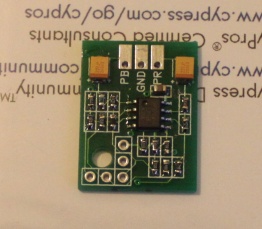
Image
Would it be reasonable to expect this to be integrated into a future version of the NESRGB?
mvsfan
Posts: 1209
Joined: Sat Oct 06, 2012 12:24 am

Re: NESRGB board available now

Post by mvsfan »

it looks to me like that pb pr encoder is designed to sit in some headers in those new, unknown through holes on the latest revision nesrgb.

thats a great idea if thats what its for.
Post Reply