My SCART to component box seems fine too. (CSY-2100 clone).Einzelherz wrote: The scart to component boxes don't add any distortion, at least not in the testing that I've seen.
NESRGB board available now
-
Sensato Kurai

- Posts: 45
- Joined: Sat Feb 25, 2006 2:06 pm
- Location: Québec, Canada
- Contact:
Re: NESRGB board available now

-
bobrocks95

- Posts: 3664
- Joined: Mon Apr 30, 2012 2:27 am
- Location: Kentucky
Re: NESRGB board available now
Didn't you make an entire thread about the top lines being offset horizontal on certain consoles? That's the distortion I'm talking about.Einzelherz wrote:The scart to component boxes don't add any distortion, at least not in the testing that I've seen.bobrocks95 wrote:Wow, just like with SCART to component boxes. Either everyone is copying each others' designs or there's some major flaw going from RGB to YPbPr that companies can't seem to get right.Sensato Kurai wrote:That PCB is pretty sweet. The only issue I have with it is that, from my experience, it gives some distortion in the top overscan on bright screens (with TG16s/Duos and SNES' at least).
PS1 Disc-Based Game ID BIOS patch for MemCard Pro and SD2PSX automatic VMC switching.
-
Einzelherz

- Posts: 1280
- Joined: Wed Apr 09, 2014 2:09 am
Re: NESRGB board available now
I did and the consensus is that it's the TV's processing of the 240p signal. The curvature occurs using other forms of input as well, like composite.
-
bobrocks95
- Posts: 3664
- Joined: Mon Apr 30, 2012 2:27 am
- Location: Kentucky
Re: NESRGB board available now
Whoops, must have missed that final conclusion. I do remember multiple people saying their CSY-2100 clone had the same warping at the top, is it everyone's TV blowing it with 240p on component?Einzelherz wrote:I did and the consensus is that it's the TV's processing of the 240p signal. The curvature occurs using other forms of input as well, like composite.
PS1 Disc-Based Game ID BIOS patch for MemCard Pro and SD2PSX automatic VMC switching.
-
RGB32E

- Posts: 1400
- Joined: Thu Nov 05, 2009 12:50 am
Re: NESRGB board available now
Looks cool! Can you provide a price and availability estimate? It looks like this just generates Pb/Pr, where RGBS & Y are already available? How come I didn't get to test one...viletim wrote:Better to wait for this one. Good performance, no adjustments. I've send them to a few people for testing already.
-
Pasky

- Posts: 699
- Joined: Mon Oct 21, 2013 3:58 am
Re: NESRGB board available now
Too many installation errors.
-
ApolloBoy

- Posts: 939
- Joined: Sat Jan 28, 2012 7:17 pm
Re: NESRGB board available now
???Pasky wrote:Too many installation errors.
-
Pasky
- Posts: 699
- Joined: Mon Oct 21, 2013 3:58 am
Re: NESRGB board available now
Search for that douche's reply when I had graphical glitching in Final Fantasy I and only Final Fantasy I. He felt he was such an expert and that it couldn't possibly be the board that he insisted I had an installation error on all my consoles (apparently). Turns out, it was the NESRGB firmware and the same timing bug that Skips reported in SMB2 and others mentioned. Same way he probably still feels he's an expert after begging christoph for a sample upscaler and now Tim for this.
-
ApolloBoy
- Posts: 939
- Joined: Sat Jan 28, 2012 7:17 pm
Re: NESRGB board available now
What does that have anything to do with what you just said?Pasky wrote:Search for that douche's reply when I had graphical glitching in Final Fantasy I and only Final Fantasy I.
And calling Tim a douche, seriously?!
-
bobrocks95
- Posts: 3664
- Joined: Mon Apr 30, 2012 2:27 am
- Location: Kentucky
Re: NESRGB board available now
Mistakes happen. I don't know the tone of the original post you're referring to, but it couldn't have been that arrogant.
And he's hardly begging here. Joking much more than anything else. If you've got beef with someone how about instead of being passive aggressive about it on a public forum, you either get over it (because it's an interaction on the internet, it's unhealthy to care that much about it) or PM the person?
And he's hardly begging here. Joking much more than anything else. If you've got beef with someone how about instead of being passive aggressive about it on a public forum, you either get over it (because it's an interaction on the internet, it's unhealthy to care that much about it) or PM the person?
He was taking a cheap stab at RGB32EApolloBoy wrote:What does that have anything to do with what you just said?Pasky wrote:Search for that douche's reply when I had graphical glitching in Final Fantasy I and only Final Fantasy I.
And calling Tim a douche, seriously?!
Last edited by bobrocks95 on Wed Jul 23, 2014 12:06 am, edited 1 time in total.
PS1 Disc-Based Game ID BIOS patch for MemCard Pro and SD2PSX automatic VMC switching.
-
Pasky
- Posts: 699
- Joined: Mon Oct 21, 2013 3:58 am
Re: NESRGB board available now
Yes, it was that arrogant, but I won't derail this thread any further. Still looking for the mini din drill size, well, exact size.
-
Pasky
- Posts: 699
- Joined: Mon Oct 21, 2013 3:58 am
Re: NESRGB board available now
12mm if anyone else didn't see it in the installation guide.
-
Taiyaki
- Posts: 1052
- Joined: Fri Apr 04, 2014 11:31 pm
Re: NESRGB board available now
Pasky's kindly modded my NES and now I'm out hunting for a scart cable. Are there any good alternatives to Tim's DIY kit or is that the recommended one?
-
Einzelherz
- Posts: 1280
- Joined: Wed Apr 09, 2014 2:09 am
Re: NESRGB board available now
The csy doesn't really modify the signal. It has to do with how any given tv parses the 240p sync. If you hook up a composite cable and tell the tv to read it as component, the curve would be there just the same. The only outliers, for me at least, are the Genesis and SMS.bobrocks95 wrote:Whoops, must have missed that final conclusion. I do remember multiple people saying their CSY-2100 clone had the same warping at the top, is it everyone's TV blowing it with 240p on component?Einzelherz wrote:I did and the consensus is that it's the TV's processing of the 240p signal. The curvature occurs using other forms of input as well, like composite.
-
tacoboy42
- Posts: 30
- Joined: Wed Jul 23, 2014 6:51 pm
Re: NESRGB board available now
Tim, Do you know when these will be available again? got a monitor and ready to do the mod but the store is currently out of stock. Thanks!
Also, this is awesome, thanks for doing this.
Also, this is awesome, thanks for doing this.
-
mufunyo
- Posts: 176
- Joined: Thu Jun 19, 2008 11:45 am
Re: NESRGB board available now
I don't know about the other consoles, but the NES always has warping at the top. It's just usually hidden by overscan. Curious to see if it'll show up on RGB with the NESRGB, but my AV Fami definitely has it on composite.
-
Windfish
- Posts: 172
- Joined: Sun Jul 13, 2014 1:57 am
Re: NESRGB board available now
Where can I buy the 3D-printed rear panel with the integrated multi-av out?
-
mickcris

- Posts: 435
- Joined: Tue Oct 08, 2013 12:43 am
- Location: Texas, USA
Re: NESRGB board available now
From Helder here:Windfish wrote:Where can I buy the 3D-printed rear panel with the integrated multi-av out?
http://www.assemblergames.com/forums/sh ... A-V-Socket
-
Pasky
- Posts: 699
- Joined: Mon Oct 21, 2013 3:58 am
Re: NESRGB board available now
Does anyone make the Mini Din 8 to SCART Euro Cables? I found Retro Cables has the adapter for the XRGB mini for the Jp21 configuration but don't see one for Euro Scart.
-
mickcris
- Posts: 435
- Joined: Tue Oct 08, 2013 12:43 am
- Location: Texas, USA
Re: NESRGB board available now
http://www.retrogamingcables.co.uk/euro ... -sale.htmlPasky wrote:Does anyone make the Mini Din 8 to SCART Euro Cables? I found Retro Cables has the adapter for the XRGB mini for the Jp21 configuration but don't see one for Euro Scart.
http://www.ebay.com/itm/Micomsoft-XRGB- ... 1365212248
-
antron

- Posts: 2861
- Joined: Wed Feb 22, 2006 7:53 pm
- Location: Egret 29, USA
Re: NESRGB board available now
I'm looking to make a custom cable to a non jamma monitor. Can anyone recommend a shielded 8 pin mini din cable to use?
Edit:
never mind, it turns out Fry's carries 8 pin mini din connectors even though they are not listed online. made a cable today.
Edit:
never mind, it turns out Fry's carries 8 pin mini din connectors even though they are not listed online. made a cable today.
Last edited by antron on Sun Jul 27, 2014 7:40 pm, edited 1 time in total.
-
greatfunky
- Posts: 2
- Joined: Sat Jun 14, 2014 2:10 pm
Re: NESRGB board available now
hi everyone
I'm finally decided to post the little problem i have encountered some month ago with my nes rgb board .
I have the last révision board with 1.7 firmware and i use the external voltage regulator , my nes is a front loader (NES-CPU-08) ntsc , mixed with the French model ( i use the case , AV box + psu and scart cable from it )
The main reason of that mix is because i'm French ! and i figured that as long as I will get a clean RGB picture , i should do it properly in 60hz full screen , full speed , so i buyed a US front loader , the other interesting part is that i get a real nintendo rgb connector and cable from the same era.
Anyway , the ntsc motherboard is working fine with the AV box and i bypassed the RGB /sync output directly to the rgb connector (that i isolated from the old output ) and off course, i configured the RGB board for a ntsc system .
My problem is with sync , i use an old crt tv that is working fine with a few others consoles but if i use CS# , luma or chroma pinout as sync signal , the picture is a little bit yellowed and dark .
Strangely i could resolve the problem for a while if i plug /unplug the scart when the nes is working , the picture became clear and perfect until a reset or turn off / on the system , then the picture return to the dark/yellowed problem.
The RGB nintendo French cable is straight through , i even try a shorter cable directly soldered on the rgb board , but i get the same result
I'm sure that is not a bad contact in the scart since i definitively solved my problem when i tryed to use PPUV as sync signal , now everything is working fine , the picture is clear all the time .
.
But i wonder why that sync problem , the strange part of that is the plug in / plug out scart fix, it seems to be an initialization signal problem....
I'm finally decided to post the little problem i have encountered some month ago with my nes rgb board .
I have the last révision board with 1.7 firmware and i use the external voltage regulator , my nes is a front loader (NES-CPU-08) ntsc , mixed with the French model ( i use the case , AV box + psu and scart cable from it )
The main reason of that mix is because i'm French
Anyway , the ntsc motherboard is working fine with the AV box and i bypassed the RGB /sync output directly to the rgb connector (that i isolated from the old output ) and off course, i configured the RGB board for a ntsc system .
My problem is with sync , i use an old crt tv that is working fine with a few others consoles but if i use CS# , luma or chroma pinout as sync signal , the picture is a little bit yellowed and dark .
Strangely i could resolve the problem for a while if i plug /unplug the scart when the nes is working , the picture became clear and perfect until a reset or turn off / on the system , then the picture return to the dark/yellowed problem.
The RGB nintendo French cable is straight through , i even try a shorter cable directly soldered on the rgb board , but i get the same result
I'm sure that is not a bad contact in the scart since i definitively solved my problem when i tryed to use PPUV as sync signal , now everything is working fine , the picture is clear all the time
But i wonder why that sync problem , the strange part of that is the plug in / plug out scart fix, it seems to be an initialization signal problem....
-
cr4zymanz0r

- Posts: 358
- Joined: Sat Oct 19, 2013 6:36 am
Re: NESRGB board available now
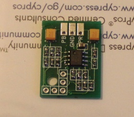
Holy crap, this sounds like EXACTLY what I need. I hate SCART connectors, switchboxes, etc. with a passion plus RGB capable CRTs in the US are hard to come by. I also hate making custom cables so I've pondered just converting RGB to component internally on my retro consoles and installing standard jacks so I can just buy standard component cables.viletim wrote:You'd be disappointed by the performance of that thing. Why do people still build crappy transistor based circuits when high speed opamps are readily available?leonk wrote:I was browsing around the net tonight when I stumbled across a neat web site and a cool idea for the NESRGB modding scene.
Imagine you have Nintendo multiAV port and an extra button/switch. The switch selects between RGB out and component out. This can be done using the tiny PCB that can be purchased here: http://www.tg16pcemods.com/.
Comments?
Better to wait for this one. Good performance, no adjustments. I've send them to a few people for testing already.
I'd probably want 15 or so of these when they're available if they're as nice and straight forward as they appear to be.
-
Einzelherz
- Posts: 1280
- Joined: Wed Apr 09, 2014 2:09 am
Re: NESRGB board available now
I just want to check to make sure this is still the correct way of setting up the expansion audio on the current revision boards.Skips wrote:The NES does not do stereo and never will. Those "stereo" mods do nothing more than separate the 5 sound channels (pulse wave 1, pulse wave 2, triangle wave, noise, and samples) and mix mono back in to give it a little more thump. CPU pin 1 is Pulse wave 1 and 2 and CPU pin 2 is Triangle wave, noise, and samples. Pretty much Pulse wave 1 and 2 sounds come out one speaker and triangle wave, noise, and samples come out the other. It is not separating the audio into right and left channels. Here is a link that explains the sounds a bit better http://www.youtube.com/watch?v=la3coK5pq5w. The audio on the NES RGB kit is simply a rebuilt mono circuit (and one that sounds quite good I might add).lettuce wrote:I need to clarify what the 3 audio solder pads are for on the NESRGB, Audio Output, Audio Input A (CPU Pin 1) and Audio Input B (CPU Pin 2.). I am want to run left and right audio (is the NESRGB even stereo?) to the 2 pins on my mini din socket (pins 1 and 2), which points on the NESRGB do i need to wire up and what are all 3 solder pads for exactly?
CPU Pin 1 goes to pad A on the kit
CPU Pin 2 goes to pad B on the kit
Pad O goes to your A/V port.
To connect expanded audio follow these steps. You will need to click on the images to get them full sized to see it properly, I threw it together in five minutes and don't feel like properly sizing this crap.
1. Connect the two points shown below in your Famicom to NES adapter.
2. Connect pin 9 to a resistor and run it to the point shown in the picture below. It is not pin 40 as stated before, they had it backwards as pin 40 is right above pin 9 (you can even see the numbering since I removed the socket in mine).
NOTE: I used a 22k Ohm resistor as anything higher made expanded audio on the Everdrive N8 too quiet.
You can also connect expanded audio with the two 1.2k resistors (and connecting it directly to audio out instead of directly to the kit) as shown earlier in the thread however this does not eliminate the buzzing like said previously, all this manages to do is make expanded audio too quiet when using the everdrive since its not being amplified. Once I turned up the stereo receiver to a level I liked the buzzing was still there with the dual 1.2k Ohm non amplified setup so I personally prefer the method shown here.
And a close up of where pin 9 needs to go.
I also don't mean to sound like a dick but Tim has how to hookup audio (without expanded audio) right on the NES RGB page. Everyone should really take a look at this and read through this entire thread before doing this mod if they have questions about it as all this stuff was answered before already.
http://etim.net.au/nesrgb/NESRGB-Pinout.pdf


-
Artemio

- Posts: 648
- Joined: Tue Jun 09, 2009 12:55 am
- Location: Mexico
- Contact:
Re: NESRGB board available now
Just so you have all the information regarding expansion audio: http://shmups.system11.org/viewtopic.ph ... 4#p1012354
-
Skips
- Posts: 404
- Joined: Tue Oct 22, 2013 3:03 am
Re: NESRGB board available now
*edit* Poster above me covered it.
I am no longer taking free or paid modding projects, please do not contact me asking for my services. Thanks  .
.
-
lettuce

- Posts: 1336
- Joined: Wed Jun 22, 2011 7:10 pm
- Location: Bedfordshire, England.
Re: NESRGB board available now
Have a JPN HVC-NES (top loader) that i will be installing the NESRGB in, do you need to do any further mods to get expansion audio from these system like you do the Front loader NES also where do you grab the audio channel from on the mainboard of the HVC-NES i know its CPU1 and 2 resistors on the frontloader but not sure on the HVC-NES?
-
lettuce
- Posts: 1336
- Joined: Wed Jun 22, 2011 7:10 pm
- Location: Bedfordshire, England.
Re: NESRGB board available now
Yeah but there is now a solder hole for the wire rather than soldering to the resistorEinzelherz wrote:I just want to check to make sure this is still the correct way of setting up the expansion audio on the current revision boards.
-
Einzelherz
- Posts: 1280
- Joined: Wed Apr 09, 2014 2:09 am
Re: NESRGB board available now
Ok so if I'm connecting pin 9 to the new pin hole in front of the resistors on the rev 1.2 board, do I use a 47k or a 100k?
-
Skips
- Posts: 404
- Joined: Tue Oct 22, 2013 3:03 am
Re: NESRGB board available now
If you are using real carts you will want a 100k potentiometer. If you are using the everdrive 100k will make expanded audio a little quiet. I was using 47k with my front loader since I mostly used the everdrive. If using both real cartridges and an ever drive your best bet is to install a switch to switch between the two OR install a potentiometer (100k) so you can control the level of the expanded audio.Einzelherz wrote:Ok so if I'm connecting pin 9 to the new pin hole in front of the resistors on the rev 1.2 board, do I use a 47k or a 100k?
I am no longer taking free or paid modding projects, please do not contact me asking for my services. Thanks .