Skips wrote:Some more Famicom love since it is seriously lacking in this thread. This time I used the stock Famicom power circuit and mounted the PCB under the Famicom PCB in order to keep the eject lever intact and functional. It appears the Famicom can take the NESRGB without the included power regulator (you still need to put thermal compound on the regulator though). Added US controller ports and an SNES AV port. Unlike the last one this one is wired for RGB, S-Video, and composite. The RF switch in the back is used to switch between the PC10 palette and the Original palette. Sadly this one is not as clean as my other work. There are still some things left to do (like use double sided sticky tape instead of shitty ass hot glue and replace the CPU) and ill be cleaning this rats nest up a good deal when I have done everything.
I also connected the NESRGB sound circuit. Like the AV Famicom it works just fine in the original Famicom. You just need to isolate pin 45 on the cartridge slot and run it through your choice of resistor to the NESRGB kit.
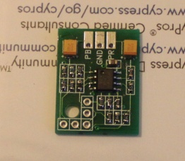
I edited your picture with what you've made different from Tim's instructions (as far as i found) (video out wiring and sound i don't really care about at this point.)
Could you explain a little short what these four points are doing?
Maybe the Gods are nice today and it's something that could expolain my problem.
Skips wrote:Some more Famicom love since it is seriously lacking in this thread. This time I used the stock Famicom power circuit and mounted the PCB under the Famicom PCB in order to keep the eject lever intact and functional. It appears the Famicom can take the NESRGB without the included power regulator (you still need to put thermal compound on the regulator though). Added US controller ports and an SNES AV port. Unlike the last one this one is wired for RGB, S-Video, and composite. The RF switch in the back is used to switch between the PC10 palette and the Original palette. Sadly this one is not as clean as my other work. There are still some things left to do (like use double sided sticky tape instead of shitty ass hot glue and replace the CPU) and ill be cleaning this rats nest up a good deal when I have done everything.
I also connected the NESRGB sound circuit. Like the AV Famicom it works just fine in the original Famicom. You just need to isolate pin 45 on the cartridge slot and run it through your choice of resistor to the NESRGB kit.
I edited your picture with what you've made different from Tim's instructions (as far as i found) (video out wiring and sound i don't really care about at this point.)
Could you explain a little short what these four points are doing?
Maybe the Gods are nice today and it's something that could expolain my problem.
(I didn't realize the pic was so big, so i linked it instead)
1.) Power and Ground
2.) My kit came with a bad 100k resistor, I replaced it but did not have any surface mount parts.
3.) expanded audio
4.) This Famicom has incredibly fragile traces for some reason (way more fragile than any NES/Famicom I have ever worked on) and that trace lifted when desoldering the PPU. Simply cutting pins puts too much stress on them so I remove the whole PPU and bend the pins up so there is no risk of damaging them.
I am no longer taking free or paid modding projects, please do not contact me asking for my services. Thanks .
Skips wrote:Some more Famicom love since it is seriously lacking in this thread. This time I used the stock Famicom power circuit and mounted the PCB under the Famicom PCB in order to keep the eject lever intact and functional. It appears the Famicom can take the NESRGB without the included power regulator (you still need to put thermal compound on the regulator though). Added US controller ports and an SNES AV port. Unlike the last one this one is wired for RGB, S-Video, and composite. The RF switch in the back is used to switch between the PC10 palette and the Original palette. Sadly this one is not as clean as my other work. There are still some things left to do (like use double sided sticky tape instead of shitty ass hot glue and replace the CPU) and ill be cleaning this rats nest up a good deal when I have done everything.
I also connected the NESRGB sound circuit. Like the AV Famicom it works just fine in the original Famicom. You just need to isolate pin 45 on the cartridge slot and run it through your choice of resistor to the NESRGB kit.
Beautiful!
I am also installing an Original Famicom and i'm having problems..
I've been trying to connect it like this 2 times, buit with the same errors, the picture only shows when i wiggle the game and flickering screen, the game actually shows up, in RGB quality, but the screen flickers and iot won't go into Intro scene of the game, though i can move the 1 player/2player selector arrow , so it's not justr a dead picture.
It's not the cartridge that is the problem, this much i know.
It felt hopeless so i removed everything again and just installed the NESRGB board straight ontp the motherboard just to see if it works, and it works flawlessly, games boot up perfectly everytime.
One thing i did differently is that the on off switch is a double pole - double throw, so the Famicom and the NESRGB is powered on at the same time (2 switches in 1 - Wash & Go) So the extra #Reset should not have to be installed to sync the NESRGB + Motherboard together.
It is very frustrating that i get the same error twice on comepltetly scratch installations according to TIm's instructions on his site.
Another issue i'm having is that when i switch from a Mini-din 8 to a Euro Scart cable, the picture is Black & White.
I had to use he Y connection to sync as the #CS did not work with the Scart connector to the TV, (No picture, only some occasional horizontal stripes as i connect the #CS.
Any ideas?
No clue dude, however Tim's instructions do not say to connect the clk and video pin to the kit. Make sure you are connecting those two. Pin 21 needs to be as short as possible and ran away from the rest the wires. I also don't have the reset pin connected because I am running off the internal regulator, I am not using the kit's extra regulator. I cut the original power PCB in half but kept the metal part of the RF box nearly complete so it could dissipate the heat and not need the extra regulator.
I am no longer taking free or paid modding projects, please do not contact me asking for my services. Thanks .
So I was not happy with the answer of having to use 30 awg wiring (i really really really hate that shit) and my need to have things clean overcame me last night. I redid nearly everything and removed the US controller ports. Since my Famicom sits 2 feet in front of me I do not need the extra cable length. Here is the inside of the system again using 28AWG wires. Its is much cleaner. I found out that it was not the wire size causing the syncing issues but the DB0 - DB7 wires being too close to the EXT wires and clock wire. I also managed to get them just flat enough to fit in the shell (BARELY).
Also I don't know if anyone has seen this but this guy has some awesome ways of making a video / power PCB's for the Famicom.
Skips wrote:
1.) Power and Ground
2.) My kit came with a bad 100k resistor, I replaced it but did not have any surface mount parts.
3.) expanded audio
4.) This Famicom has incredibly fragile traces for some reason (way more fragile than any NES/Famicom I have ever worked on) and that trace lifted when desoldering the PPU. Simply cutting pins puts too much stress on them so I remove the whole PPU and bend the pins up so there is no risk of damaging them.
Thanks for the replies!
So the AC/RF board only needs those two wires to work? What are the other ones for?
Skips wrote:
No clue dude, however Tim's instructions do not say to connect the clk and video pin to the kit. Make sure you are connecting those two. Pin 21 needs to be as short as possible and ran away from the rest the wires.
Yeah i saw that, though i might have made the video lead too long, what symptom would that give me?
Skips wrote:
1.) Power and Ground
2.) My kit came with a bad 100k resistor, I replaced it but did not have any surface mount parts.
3.) expanded audio
4.) This Famicom has incredibly fragile traces for some reason (way more fragile than any NES/Famicom I have ever worked on) and that trace lifted when desoldering the PPU. Simply cutting pins puts too much stress on them so I remove the whole PPU and bend the pins up so there is no risk of damaging them.
Thanks for the replies!
So the AC/RF board only needs those two wires to work? What are the other ones for?
Skips wrote:
No clue dude, however Tim's instructions do not say to connect the clk and video pin to the kit. Make sure you are connecting those two. Pin 21 needs to be as short as possible and ran away from the rest the wires.
Yeah i saw that, though i might have made the video lead too long, what symptom would that give me?
When I had it too long it took about a second longer for the NESRGB to come up and give video and it had a lot more noise at startup.
There are 2 ground and 5v pins, audio, and video. I cant remember what the last one was off the top of my head.
I am no longer taking free or paid modding projects, please do not contact me asking for my services. Thanks .
you are in europe right, jeppen? if so you need tims scart adapter with a charge pump built into it. it will allow the tv to select the right mode for the nesrgb.
Skips wrote:
1.) Power and Ground
2.) My kit came with a bad 100k resistor, I replaced it but did not have any surface mount parts.
3.) expanded audio
4.) This Famicom has incredibly fragile traces for some reason (way more fragile than any NES/Famicom I have ever worked on) and that trace lifted when desoldering the PPU. Simply cutting pins puts too much stress on them so I remove the whole PPU and bend the pins up so there is no risk of damaging them.
Thanks for the replies!
So the AC/RF board only needs those two wires to work? What are the other ones for?
Skips wrote:
No clue dude, however Tim's instructions do not say to connect the clk and video pin to the kit. Make sure you are connecting those two. Pin 21 needs to be as short as possible and ran away from the rest the wires.
Yeah i saw that, though i might have made the video lead too long, what symptom would that give me?
When I had it too long it took about a second longer for the NESRGB to come up and give video and it had a lot more noise at startup.
There are 2 ground and 5v pins, audio, and video. I cant remember what the last one was off the top of my head.
Cool! Thanks, i will also strip it down to the 2 wires
mvsfan wrote:you are in europe right, jeppen? if so you need tims scart adapter with a charge pump built into it. it will allow the tv to select the right mode for the nesrgb.
Yeah i'm in Europe (Scandinavia), so this would make it color?
If so, Would it be possible to build this modification instead of ordering it from Tim?
In other words i have no idea what a charge pump is Though i'm all for DYI's
I'm trying to take the power/av box off of my motherboard but I don't seem to be properly equipped to deal with the four wide/flat joints. Is this what a solder braid is for?
a charge pump takes the 5v output of the console and converts it into 12v. you need this for scart switching in order to select 4:3 mode and to select rgb or the tv wont display properly. Im not exactly sure how to accomplish it since i live in the U.S. but perhaps one of our european friends can help you more.
Pin 8 on the scart connector selects your video aspect ratio - must be 12v for 4:3
pin 16 selects rgb mode. Must be 3v to select Rgb.
tim sells a scart adapter that has a charge pump built into it, but mabeye if you ask him nicely he will sell you one seperate.
mvsfan wrote:a charge pump takes the 5v output of the console and converts it into 12v. you need this for scart switching in order to select 4:3 mode and to select rgb or the tv wont display properly. Im not exactly sure how to accomplish it since i live in the U.S. but perhaps one of our european friends can help you more.
Pin 8 on the scart connector selects your video aspect ratio - must be 12v for 4:3
pin 16 selects rgb mode. Must be 3v to select Rgb.
tim sells a scart adapter that has a charge pump built into it, but mabeye if you ask him nicely he will sell you one seperate.
Thanks! Yes i have ordered it now, i needed the extra straight minidin 8 cable anyway for my frontloader
Hope it gets here soon
Can someone please tell me what the farad rating is on that smd capacitor that is being pointed to in the picture my NesRGB is missing it and I want to replace it I think its not directional Thanks
RosserRooster wrote:Can someone please tell me what the farad rating is on that smd capacitor that is being pointed to in the picture my NesRGB is missing it and I want to replace it I think its not directional Thanks
I can't get a good read on it in circuit, but i'm betting it's just a .1uF ceramic.
Tim would have to verify.
Don't know if this is of any interest to anyone but I did this color palette comparison video. The video ends with 5 seconds of Loopy's Palette Test. The video is blurry because of an encoding mistake I made but it still gives a good idea.
Sensato Kurai wrote:Don't know if this is of any interest to anyone but I did this color palette comparison video. The video ends with 5 seconds of Loopy's Palette Test. The video is blurry because of an encoding mistake I made but it still gives a good idea.
Zets13 wrote:Nice comparison. After watching that it definitely looks like the colors are indeed livened up a bit even in "Natural" RGB relative to composite.
I'd like to mention that the luminance contrast on that composite capture looks a bit high, causing colours to wash out. The sky in SMB3 definitely doesn't look that grey normally, on any TV.
mufunyo wrote:
I'd like to mention that the luminance contrast on that composite capture looks a bit high, causing colours to wash out. The sky in SMB3 definitely doesn't look that grey normally, on any TV.
That's possible. I tried adjusting the composite signal through the XRGBMini as close as possible to what I got on another monitor but it might not be perfect. Thanks for the input!
Sensato Kurai wrote:Don't know if this is of any interest to anyone but I did this color palette comparison video. The video ends with 5 seconds of Loopy's Palette Test. The video is blurry because of an encoding mistake I made but it still gives a good idea.
I was browsing around the net tonight when I stumbled across a neat web site and a cool idea for the NESRGB modding scene.
Imagine you have Nintendo multiAV port and an extra button/switch. The switch selects between RGB out and component out. This can be done using the tiny PCB that can be purchased here: http://www.tg16pcemods.com/.
leonk wrote:I was browsing around the net tonight when I stumbled across a neat web site and a cool idea for the NESRGB modding scene.
Imagine you have Nintendo multiAV port and an extra button/switch. The switch selects between RGB out and component out. This can be done using the tiny PCB that can be purchased here: http://www.tg16pcemods.com/.
Comments?
That PCB is pretty sweet. The only issue I have with it is that, from my experience, it gives some distortion in the top overscan on bright screens (with TG16s/Duos and SNES' at least). I plan to install one in an RGB modded Top Loader soon. I have an composite modded Top Loader that I'd like to upgrade to component.
Sensato Kurai wrote:That PCB is pretty sweet. The only issue I have with it is that, from my experience, it gives some distortion in the top overscan on bright screens (with TG16s/Duos and SNES' at least).
Wow, just like with SCART to component boxes. Either everyone is copying each others' designs or there's some major flaw going from RGB to YPbPr that companies can't seem to get right.
leonk wrote:I was browsing around the net tonight when I stumbled across a neat web site and a cool idea for the NESRGB modding scene.
Imagine you have Nintendo multiAV port and an extra button/switch. The switch selects between RGB out and component out. This can be done using the tiny PCB that can be purchased here: http://www.tg16pcemods.com/.
Comments?
You'd be disappointed by the performance of that thing. Why do people still build crappy transistor based circuits when high speed opamps are readily available?
Better to wait for this one. Good performance, no adjustments. I've send them to a few people for testing already.
Yes I heard about that through the grapevine. Any idea when it will be available?
I'd love to test one.
Does anyone know where to get a good quality shielded scart cable that fits the connector Tim sends with his kits? Or can make me one?
I've contacted retro-console-accessories, but they are very slow to respond and I need it pretty quickly.
Sensato Kurai wrote:That PCB is pretty sweet. The only issue I have with it is that, from my experience, it gives some distortion in the top overscan on bright screens (with TG16s/Duos and SNES' at least).
Wow, just like with SCART to component boxes. Either everyone is copying each others' designs or there's some major flaw going from RGB to YPbPr that companies can't seem to get right.
The scart to component boxes don't add any distortion, at least not in the testing that I've seen.