NESRGB board available now

The place for all discussion on gaming hardware
User avatar
Voultar
Posts: 550
Joined: Fri Jan 10, 2014 8:29 pm
Location: USA

Re: NESRGB board available now

Post by Voultar »

Elrinth wrote:I have also made sure the DP0-7 and EXT1-4 pins from nesrgb board doesn't connect to the main board respective pins (the pins seen here: http://i125.photobucket.com/albums/p55/ ... 28b1b7.jpg).

Why is this necessary on the Twin Famicom?
Elrinth
Posts: 307
Joined: Thu Feb 07, 2013 2:46 pm

Re: NESRGB board available now

Post by Elrinth »

@Voultar: I have no idea. I ask back to you, why would it be different from NES and normal Famicom?
During desoldering of PPU the pin padcircle on 13 and 14 were destroyed on the bottom of the board, I would like to know where they go on a sharp twin famicom.
This does not sound good. How did this happen, too much heat? Im guessing you have continuity again since you posted the pin-check spreadsheet. Still, it may be related if the PPU got too hot in that area.
If you desoldor/solder many times cuz the pin would not get loose it is likely you'll end up destroying something... In this case, I destroyed the pad circles on those pins. Yes I have fixed continuity again.
14 is EXT so it only needed GND. But 13 was actually connected somewhere.
Elrinth
Posts: 307
Joined: Thu Feb 07, 2013 2:46 pm

Re: NESRGB board available now

Post by Elrinth »

Pasky wrote:On a regular NES:

PPU pin 13 goes to pin 4 on the cartridge connecter (PRG A9) and pin 22 on the video sram.
PPU pin 14 goes to pin 3 on the cartridge connecter (PRG A10) and pin 19 on the video sram.

No idea how different a twin famicom is.
Here's how different it is:
http://nesdev.com/Ntd_8bit.jpg
User avatar
Pasky
Posts: 699
Joined: Mon Oct 21, 2013 3:58 am

Re: NESRGB board available now

Post by Pasky »

BuckoA51 wrote:So have Analogue Interactive licensed this board from you Tim? http://www.analogueinteractive.com/inde ... nalogue-nt

It's just a Super 8 PCB + NESRGB in an aluminum case. Nothing special.
User avatar
Pasky
Posts: 699
Joined: Mon Oct 21, 2013 3:58 am

Re: NESRGB board available now

Post by Pasky »

Elrinth wrote:
Pasky wrote:On a regular NES:

PPU pin 13 goes to pin 4 on the cartridge connecter (PRG A9) and pin 22 on the video sram.
PPU pin 14 goes to pin 3 on the cartridge connecter (PRG A10) and pin 19 on the video sram.

No idea how different a twin famicom is.
Here's how different it is:
http://nesdev.com/Ntd_8bit.jpg
It's exactly the same, I'm a moron and read the schematic wrong and was looking at the cpu pins =/. I was using that exact schematic.
Elrinth
Posts: 307
Joined: Thu Feb 07, 2013 2:46 pm

Re: NESRGB board available now

Post by Elrinth »

Pasky wrote:
Elrinth wrote:
Pasky wrote:On a regular NES:

PPU pin 13 goes to pin 4 on the cartridge connecter (PRG A9) and pin 22 on the video sram.
PPU pin 14 goes to pin 3 on the cartridge connecter (PRG A10) and pin 19 on the video sram.

No idea how different a twin famicom is.
Here's how different it is:
http://nesdev.com/Ntd_8bit.jpg
It's exactly the same, I'm a moron and read the schematic wrong and was looking at the cpu pins =/. I was using that exact schematic.
Yeah, Famicom PPU pin 14 goes to GND only (it's EXT). And PPU pin 13 goes to LS139 only.
Last edited by Elrinth on Fri Mar 14, 2014 3:29 pm, edited 1 time in total.
LaC
Posts: 38
Joined: Fri Feb 01, 2013 12:35 am
Location: Champaign, IL

Re: NESRGB board available now

Post by LaC »

Does anyone know where to get a genesis 2 style scart cable made for the NESRGB?
I have my nesrgb wired to a genesis 2 style port, but when I use the genesis2 scart cable I got from retro console accessories I get a dark image and have to increase the brightness of my PVM to compensate. I found out this is because it looks like they have 75 ohms on the rgb lines, which makes sense for a genesis2. However, I opened the scart cable to remove the resistors and it appears they have glued the resistors into the cable, and are pretty much impossible to remove. (why do they do this?!)
I may end up just ordering from http://www.retrogamingcables.com/, because I know they don't glue their components.
Zets13
Posts: 142
Joined: Wed Nov 02, 2011 10:53 pm

Re: NESRGB board available now

Post by Zets13 »

Remove them from the NESRGB board itself.
User avatar
game-tech.us
Posts: 173
Joined: Fri Aug 23, 2013 12:24 am

Re: NESRGB board available now

Post by game-tech.us »

If anyone is interested I will be adding an nesrgb mod to a NES Test Station!
First vid just showing how it works.

Review of Helder's 3D printed nes-101 rear panel with snes multi coming soon.
sazyario
Posts: 65
Joined: Tue Jan 07, 2014 2:03 pm

Re: NESRGB board available now

Post by sazyario »

Ordered my NESRGB kit from the USA Distributior.
It was delivered less than 48 hours after ordering... May help that I only live an hour and a half from him...


Anyway... What size drill bits do I want to use to the drill the holes for the mini din, audio jack and palette switch?

Also, it appears I got a different type of switch. I only have 3 terminals to solder to on the switch instead of 6... This seems odd. I feel in the very least there should be a 4th post for ground...

My board has a sticker on it that says 1.4


Also, looking at the mini din breakout board I do to know what 'v' is for. Composite video or composite sync?
User avatar
mickcris
Posts: 435
Joined: Tue Oct 08, 2013 12:43 am
Location: Texas, USA

Re: NESRGB board available now

Post by mickcris »

sazyario wrote:Ordered my NESRGB kit from the USA Distributior.
It was delivered less than 48 hours after ordering... May help that I only live an hour and a half from him...


Anyway... What size drill bits do I want to use to the drill the holes for the mini din, audio jack and palette switch?

Also, it appears I got a different type of switch. I only have 3 terminals to solder to on the switch instead of 6... This seems odd. I feel in the very least there should be a 4th post for ground...

My board has a sticker on it that says 1.4


Also, looking at the mini din breakout board I do to know what 'v' is for. Composite video or composite sync?
I would assume that the 1.4 sticker means it has v1.4 flashed to it. here is the switch wiring info:
http://etim.net.au/nesrgb/switch/
User avatar
Josh128
Posts: 2238
Joined: Thu Jan 16, 2014 9:01 am

Re: NESRGB board available now

Post by Josh128 »

sazyario wrote:Ordered my NESRGB kit from the USA Distributior.
It was delivered less than 48 hours after ordering... May help that I only live an hour and a half from him...


Anyway... What size drill bits do I want to use to the drill the holes for the mini din, audio jack and palette switch?

Also, it appears I got a different type of switch. I only have 3 terminals to solder to on the switch instead of 6... This seems odd. I feel in the very least there should be a 4th post for ground...

My board has a sticker on it that says 1.4


Also, looking at the mini din breakout board I do to know what 'v' is for. Composite video or composite sync?
Who is the US distributor? Gametech?

V is for composite video. CS# is composite sync. Use CS# if your setup supports it. I think the switch you have can only support 2 palettes. Solder ground to center and your palettes of choice to either side. I used a 3/8 bit for my mini din, was a bit too small, probably could have used a 7/16. Dont remember for the jack and switch.
User avatar
mickcris
Posts: 435
Joined: Tue Oct 08, 2013 12:43 am
Location: Texas, USA

Re: NESRGB board available now

Post by mickcris »

Josh128 wrote:
sazyario wrote:Ordered my NESRGB kit from the USA Distributior.
It was delivered less than 48 hours after ordering... May help that I only live an hour and a half from him...


Anyway... What size drill bits do I want to use to the drill the holes for the mini din, audio jack and palette switch?

Also, it appears I got a different type of switch. I only have 3 terminals to solder to on the switch instead of 6... This seems odd. I feel in the very least there should be a 4th post for ground...

My board has a sticker on it that says 1.4


Also, looking at the mini din breakout board I do to know what 'v' is for. Composite video or composite sync?
Who is the US distributor? Gametech?

V is for composite video. CS# is composite sync. Use CS# if your setup supports it. I think the switch you have can only support 2 palettes. Solder ground to center and your palettes of choice to either side. I used a 3/8 bit for my mini din, was a bit too small, probably could have used a 7/16. Dont remember for the jack and switch.
v1.4 can use an on-off-on switch. see here:
http://etim.net.au/nesrgb/switch/

Tim's page says the US distributer is in Ohio so its not gametech.
User avatar
game-tech.us
Posts: 173
Joined: Fri Aug 23, 2013 12:24 am

Re: NESRGB board available now

Post by game-tech.us »

mickcris wrote:Tim's page says the US distributer is in Ohio so its not gametech.
Nope, not me...
Tim told the name of the guy, but it didn't ring any bells, for a minute I thought maybe stoneagegamer?
User avatar
ApolloBoy
Posts: 938
Joined: Sat Jan 28, 2012 7:17 pm

Re: NESRGB board available now

Post by ApolloBoy »

Pretty sure it's Yurkie on AtariAge.
leonk
Posts: 1092
Joined: Sun Mar 13, 2011 9:29 pm
Location: Toronto, Canada

Re: NESRGB board available now

Post by leonk »

I just "blasted" my original NESRGB from 1.0 to 1.4 .. figured I'd share this tip with some of you (Pg 64 of this thread has a good image to follow).

- I got my blaster for dirt cheap from the UK - got here in less than a week
- I chopped the IDC cable it came with to a length that allowed me to solder it in place on the NESRGB, and then tuck it away under the board when not in use. This way, in the future, all it takes is 4 screws and I'm inside the NES blasting away. :)
- I only have Mac's at home.. but the software worked perfectly on my MacBook Pro using VMWare with Windows XP image (I'm a sucker for XP .. most dev tools run in DOS/16-bit and Windows 7 64 has no 16 bit DOS support unless you use DOSBox, but it's darn slow)

I still have 1/2 an IDC cable which I can use in another system. These cables are cheap and can be purchased for a song at your local electronics depot.
User avatar
Tempest_2084
Posts: 595
Joined: Tue Feb 04, 2014 3:05 pm

Re: NESRGB board available now

Post by Tempest_2084 »

ApolloBoy wrote:Pretty sure it's Yurkie on AtariAge.
That would make sense. He's doing my NES and he is in OH. He said he got his boards directly from the guy in Australia.
Elrinth
Posts: 307
Joined: Thu Feb 07, 2013 2:46 pm

Re: NESRGB board available now

Post by Elrinth »

I have been unsuccessful in installing the rgbmod in two famicoms now, yes I have two broken Sharp Twin Famicoms now :( This time I will request someone else to do it, for a fee ofcourse. Anyone (preferable in sweden) who could do it, please PM me. Currently I've got game-tech in mind.
Zets13
Posts: 142
Joined: Wed Nov 02, 2011 10:53 pm

Re: NESRGB board available now

Post by Zets13 »

Elrinth wrote:I have been unsuccessful in installing the rgbmod in two famicoms now, yes I have two broken Sharp Twin Famicoms now :( This time I will request someone else to do it, for a fee ofcourse. Anyone (preferable in sweden) who could do it, please PM me. Currently I've got game-tech in mind.
What happened?
Elrinth
Posts: 307
Joined: Thu Feb 07, 2013 2:46 pm

Re: NESRGB board available now

Post by Elrinth »

Zets13 wrote:
Elrinth wrote:I have been unsuccessful in installing the rgbmod in two famicoms now, yes I have two broken Sharp Twin Famicoms now :( This time I will request someone else to do it, for a fee ofcourse. Anyone (preferable in sweden) who could do it, please PM me. Currently I've got game-tech in mind.
What happened?
They don't work when I turn them on. One has a led light which indicates if it's on or not which is never lit. The other I simply try famicom disk mode with and the diskette station doesn't make any sound so it doesn't work either.
User avatar
yxkalle
Posts: 135
Joined: Sun Feb 16, 2014 4:32 am
Location: Stockholm, Sweden

Re: NESRGB board available now

Post by yxkalle »

I can do it!
Jag kan göra det!

//Rikard på japanspel.se
User avatar
Josh128
Posts: 2238
Joined: Thu Jan 16, 2014 9:01 am

Re: NESRGB board available now

Post by Josh128 »

Elrinth wrote:
Zets13 wrote:
Elrinth wrote:I have been unsuccessful in installing the rgbmod in two famicoms now, yes I have two broken Sharp Twin Famicoms now :( This time I will request someone else to do it, for a fee ofcourse. Anyone (preferable in sweden) who could do it, please PM me. Currently I've got game-tech in mind.
What happened?
They don't work when I turn them on. One has a led light which indicates if it's on or not which is never lit. The other I simply try famicom disk mode with and the diskette station doesn't make any sound so it doesn't work either.
Man thats disheartening. It is quite a daunting mod though, with about a hundred things that could go wrong. I know when I first powered mine on I wasnt even really expecting it to work, when it did I just had a look of disbelief (and relief!). But, if it hadnt worked, I would have troubleshot as you did, and if it still didnt work after many hours (Im sure) of trying everything, I'd have sent it off as well.

Very curious (as Im sure you are) to see what they find wrong...
leonk
Posts: 1092
Joined: Sun Mar 13, 2011 9:29 pm
Location: Toronto, Canada

Re: NESRGB board available now

Post by leonk »

Josh128 wrote:It is quite a daunting mod though, with about a hundred things that could go wrong. I know when I first powered mine on I wasnt even really expecting it to work, when it did I just had a look of disbelief (and relief!).
You guys should have a bit more confidence in yourselves .. it's not rocket science. :) It's 1/3 having the right tools, 1/3 knowing how to use them and 1/3 confidence that you can do it.

Imagine if a heart doctor was surprised every time one of his patients wakes up after an operation! :lol: :lol: :lol:
User avatar
Josh128
Posts: 2238
Joined: Thu Jan 16, 2014 9:01 am

Re: NESRGB board available now

Post by Josh128 »

leonk wrote:
Josh128 wrote:It is quite a daunting mod though, with about a hundred things that could go wrong. I know when I first powered mine on I wasnt even really expecting it to work, when it did I just had a look of disbelief (and relief!).
You guys should have a bit more confidence in yourselves .. it's not rocket science. :) It's 1/3 having the right tools, 1/3 knowing how to use them and 1/3 confidence that you can do it.

Imagine if a heart doctor was surprised every time one of his patients wakes up after an operation! :lol: :lol: :lol:
Thing is, this is an old piece of tech-- I have to wonder how long it would last (with its electrolytic caps) even without what amounted to a heart transplant & upgrade(on an old friend, no less). It wasnt that I thought I hadnt wired it correctly, I was worried about how the PPU held up through the admittedly agonizing removal. That and it looked like someone had fiddled with the Altera chip on my NESRGB-- some of the tiny legs looked as if they had been soldered to or re-soldered (I just figured perhaps it was something Tim did to fix the vram/firmware issue, as mine must have been one of the first that came with the issue resolved. I actually placed the order before Tim was aware of the problem, but it took over a month for me to get it).

In the end though, I have to say Nintendo consoles are some well made electronics. I had issues modding my N64 due to a bad solder job on the 7314 chip I ordered from Ebay. Troubleshooting it I must have cut it in and out of the 64 3 or 4 times starting with a topside install and ending with a bottom side one. Despite the trauma I put it through, the 64 took it like a champ.
leonk
Posts: 1092
Joined: Sun Mar 13, 2011 9:29 pm
Location: Toronto, Canada

Re: NESRGB board available now

Post by leonk »

For those of you that are not subscribed to Jason's youtube feed (shame on you!) he posted the review of the 3D printed multiAV port. For what it's worth:

Positive:
- I'm surprised by the quality of the connector - it does seem top notch
- Jason always puts out entertaining videos

Negative:
- they have to fix the white color
- they should be including the AC plug with the kit (How much are those Jason? 99 cents??)
- Jason, were you using your mouth as a third hand? If I'm not mistaken, the wire you were holding in your mouth is 40% lead! I have reverse tweezers for this reason (i.e. the type that are typically closed and require you to squeeze to open - excellent 3rd hand)

Overall, for those of you that want a quick, no frills, solution.. it's probably a great buy for you. I strongly feel that using a Nintendo multiAV port (no matter how you get it) is the best way to use the NESRGB in an NES.

Jason, have you ever tried using a multi-AV port from a GameCube? You'll be surprised by how different it is from the SNES. It does NOT have that silly key. It's a plain jane rectangular hole. Very easy to cut and make it look as good as OEM. The fact that the entire port is also ground shielded in a bonus.

Always looking forward to see your videos .. keep up the excellent work!!
User avatar
ApolloBoy
Posts: 938
Joined: Sat Jan 28, 2012 7:17 pm

Re: NESRGB board available now

Post by ApolloBoy »

leonk wrote:they should be including the AC plug with the kit (How much are those Jason? 99 cents??)
They do, as I got one with mine. I assume Jason decided not to have those included since he already has a bag of them.
User avatar
game-tech.us
Posts: 173
Joined: Fri Aug 23, 2013 12:24 am

Re: NESRGB board available now

Post by game-tech.us »

leonk wrote:For those of you that are not subscribed to Jason's youtube feed (shame on you!) he posted the review of the 3D printed multiAV port. For what it's worth:

Positive:
- I'm surprised by the quality of the connector - it does seem top notch
- Jason always puts out entertaining videos

Negative:
- they have to fix the white color
- they should be including the AC plug with the kit (How much are those Jason? 99 cents??)
- Jason, were you using your mouth as a third hand? If I'm not mistaken, the wire you were holding in your mouth is 40% lead! I have reverse tweezers for this reason (i.e. the type that are typically closed and require you to squeeze to open - excellent 3rd hand)

Overall, for those of you that want a quick, no frills, solution.. it's probably a great buy for you. I strongly feel that using a Nintendo multiAV port (no matter how you get it) is the best way to use the NESRGB in an NES.

Jason, have you ever tried using a multi-AV port from a GameCube? You'll be surprised by how different it is from the SNES. It does NOT have that silly key. It's a plain jane rectangular hole. Very easy to cut and make it look as good as OEM. The fact that the entire port is also ground shielded in a bonus.

Always looking forward to see your videos .. keep up the excellent work!!
Vid link.
Thanks for the props Leon.
The kit does come with the power port, sorry i forgot to mention that. I just happen to have a bag full of them already and wanted a little discount for not getting them.
Yes I did put it in my mouth. For a long time I was worried lead was building up in my body after 10 plus years of constantly touching solder, but I had a bunch of blood tests done last fall that showed negligible amounts, so using my lips once in a great while and touching it with my fingers no longer worries me, but that is a top tip about reverse tweezers, got a link? It would be hilarious is they made ones specifically for putting in your mouth for idiots like me!
I've never used the GC multi, I really don't like the idea of cutting the access hole in the mobo to get to the pins, nor installing it upside down, the snes connector is easier and i've gotten used to making the hole, but the 3D piece is way easier for sure!
I hope they do nail down the paint process soon though...
leonk
Posts: 1092
Joined: Sun Mar 13, 2011 9:29 pm
Location: Toronto, Canada

Re: NESRGB board available now

Post by leonk »

That's cool. I understand your concern with the hole or upside down. The SNES pins at the back can be bend straight and have wire soldered to it. The GC connector can't. You have to drill the hole or solder it upside down. I wouldn't be too concerned with the hole. The FamicomAV and newer systems all have pins going down into the PCB. The hole is so small, it should have no effect on structure or ground plain. At the end of the day, it's all a personal choice, and it's nice to have more options.

Google reverse tweezers .. lots of them out there. Here's one similar to what I got:

http://www.amazon.com/Testors-8942T-Rev ... B003ZD1148
sazyario
Posts: 65
Joined: Tue Jan 07, 2014 2:03 pm

Re: NESRGB board available now

Post by sazyario »

My kit doesn't seem to be working...

I get a small audio pop when I switch my nes on.

I'm looking at various pictures and I didnt make a jumper from +5v from the NESRGB to the pin on the PPU. I just bridged the J3 jumper...

Took audio from pins 1 & 2 directly to the audio jack.

Tried using CS# and C to the pin marked 'V' on the Mini-DIN PCB.

Any help guys?

EDIT***
Ok, using PPUV for Sync and I have video.

Now I have several new problems...
1.. No audio.
I have left and right connected to the left and right posts of the audio jack, and the center I connected ground.

2.. No input. Nothing. I reflowed my controller ports and that didnt help

3.. Dont have all 3 palettes.

EDIT2***
Fixed it all...
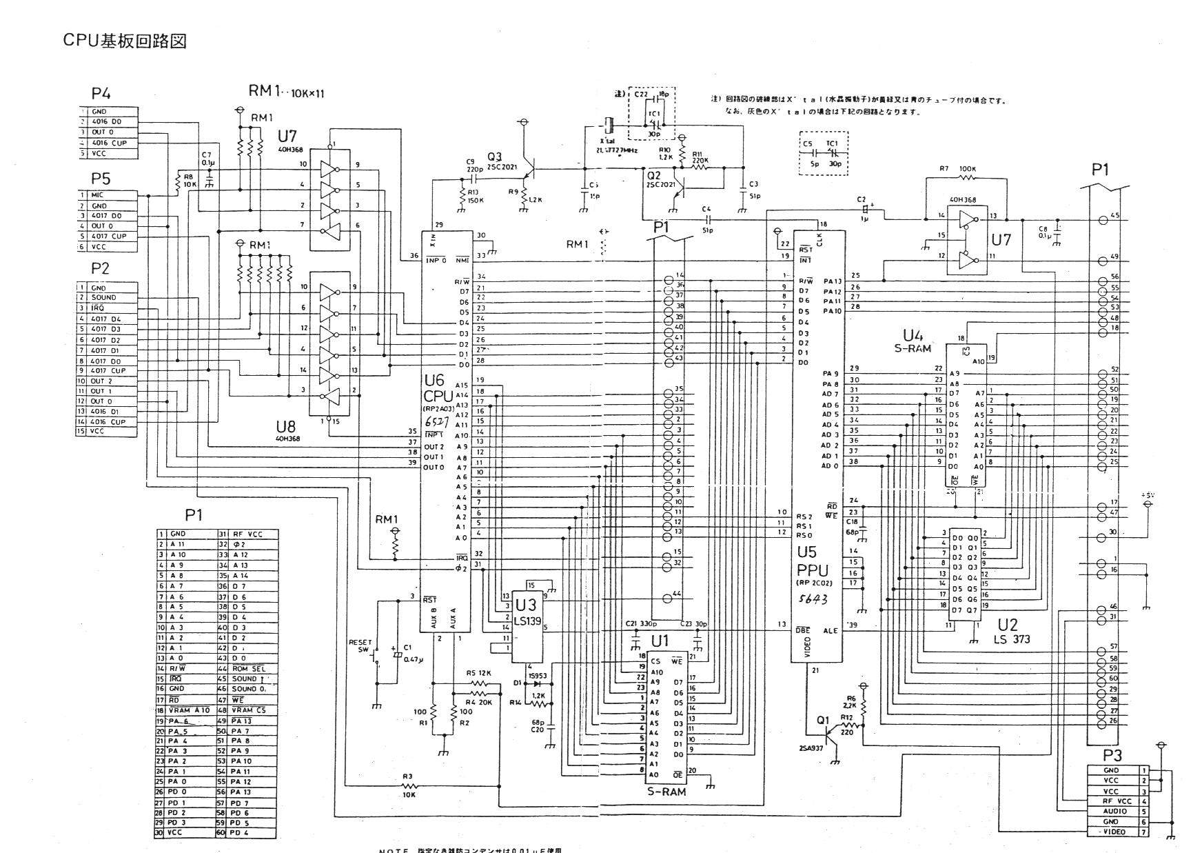
I think I tapped the wrong pins on the CPU for the audio... That is why the inputs werent working.
Decided to tap audio from R6 and R7 instead.

Fixed palette by paying closer attention to the wiring diagram given by Tim's website...

I guess I shouldn't try doing stuff like this drunk and tired.

Took apprx 8 hours for me to complete. I'm ok with that.

EDIT3***
Image

As you can see everything fits in the AV panel. If I had the switch any further left it would not have worked.
I guess all I can say in hind sight is I wish I didnt try to put Super glue on the small lip of the Mini DIN connector that meets with the panel, and that I had the switch up higher to be level with the audio jack.
I like the switch's placement because it is just long enough that I can flip it where it sits on my shelf.
User avatar
lettuce
Posts: 1336
Joined: Wed Jun 22, 2011 7:10 pm
Location: Bedfordshire, England.

Re: NESRGB board available now

Post by lettuce »

Jeppen wrote:I was missing some info on this, so i thought i'd just sum it up for anyone else who might need it.

viletim wrote: The PLD on the NESRGB board does need power while being programmed. The programmers I have sent out have all been modified to power the board while programming it.
______
*edit Jeppen* As an alternative you could simply have have the NES powered on. (i'm pretty sure i read that in this thread)
______
viletim wrote: I simply installed a 3.3V LDO voltage regulator and connected the output to pin 4 (VCC sense).
Image

You don't need to do this if you can find another way to power the board. Either by applying 3.3V to the JTAG port power terminals or +5V to the power input solder pads (near J3).
viletim wrote:The programmer comes with a short 10p IDC ribbon cable. I cut off one end and solder the wire to little piece of phenolic board with the 6p header mounted. I put tape over it afterwards which I have removed for the photo.
Image

Here's a pic i found of the cable's original pin
number 1 to 10 are going from left to right in this pic.
Image

Where and what to connect to the NESRGB (Pics from Tim's site:
http://etim.net.au/nesrgb/background_fault/

JTAG Pinout

+3.3V power rail
Ground
TDO
TCK
TDI
TMS

Image Image


McCracAttack's troubleshooting and success with the USB blaster:

The programmer on TIM's site is now also 13.1

My win 7 couldn't install the USB blaster drivers correctly when i plugged in the USB cable, i found this page with instructions on how to manually install the correct drivers and have your PC recognize it on Windows 7 and Vista.
Not the drivers are already on your computer in your C:/Altera folder so just follow the instructions in the below link and you'll be fine.

http://www.altera.com/download/drivers/ ... vista.html

McCracAttack wrote:
CkRtech wrote:It looks like the version that Tim supplied is Quartus II version 11.1.

The Altera website currently has a version 13.1. There is a free version and a licensed version, and the licensed version gives you a 30 day trial.

https://www.altera.com/download/sw/dnl-sw-index.jsp

Newer isn't always better, but perhaps you could give version 13.1 a try. You may need to cleanse your system of 11.1 prior to installing 13.1 - I am not certain. I haven't received a Blaster yet, so I can only make suggestions based on what I see on the web.
Oh man this was so promising! Thank you! The 13.1 programmer that came with the free Web Edition bundle can see the USB Blaster just fine! But now I'm getting a new error message.

Code: Select all

Info (209060): Started Programmer operation at Thu Jan 30 22:24:25 2014
Error (209040): Can't access JTAG chain
Error (209053): Unexpected error in JTAG server -- error code 44
Error (209012): Operation failed
Info (209061): Ended Programmer operation at Thu Jan 30 22:24:25 2014
More fiddling. But it certainly seems like Windows 7 users need the newer software and drivers than what Tim provided.

Update: Okay, I get the exact same error message when I unplug the USB Blaster from the board so it looks like my custom connector needs work.

Update 2: I've check and recheck the connections and as near as I can tell they're sound. Back to fiddling I guess. :cry:

Update 3: SUCCESS!!! According to this article some of the pins are powered by the target device. The NES had to be plugged in and turned on in order for the reprogramming to work. And work it did! The problem seems 100% fixed now! Though I guess people who were planning to reprogram boards before they installed them will have to find a way to power them first.

Thanks to nesfreak and CkRtech for your help. Hopefully someone else will learn from my mistakes.
Does anyone in the UK have one of these USB blasters than can lend me, so i can update my NESRGB??
Post Reply