I came into possession of this unit awhile back and it only has a composite jack. Looking at the IC seems to show it is RGB modable.
This is a VCR combo set and it looks like it uses SVideo internally to connect the built in VCR to the TV. I was curious if i could possibly add SVideo too, as i see some Luma/Chroma pins on the IC. Anyone know which pins i should start with and how i would go about switching it on?
https://imgur.com/a/qCefHUc
TV RGB mod thread
Re: TV RGB mod thread
This looks like one I recently saw that was set in software to Digital RGB. You might be lucky. If not could use I2C serial intercept to set it to analog RGB.retrozar wrote:I came into possession of this unit awhile back and it only has a composite jack. Looking at the IC seems to show it is RGB modable.
This is a VCR combo set and it looks like it uses SVideo internally to connect the built in VCR to the TV. I was curious if i could possibly add SVideo too, as i see some Luma/Chroma pins on the IC. Anyone know which pins i should start with and how i would go about switching it on?
https://imgur.com/a/qCefHUc
___________________________________________________
MarkOZLAD
OSD/External RGB Mux Diagram
OSD/External RGB Mux Resistor Value Table 0.7Vp-p : 0.5Vp-p
"Imagine toggle switch OSD modding a TV in 2019" - maxtherabbit
MarkOZLAD
OSD/External RGB Mux Diagram
OSD/External RGB Mux Resistor Value Table 0.7Vp-p : 0.5Vp-p
"Imagine toggle switch OSD modding a TV in 2019" - maxtherabbit

Re: TV RGB mod thread
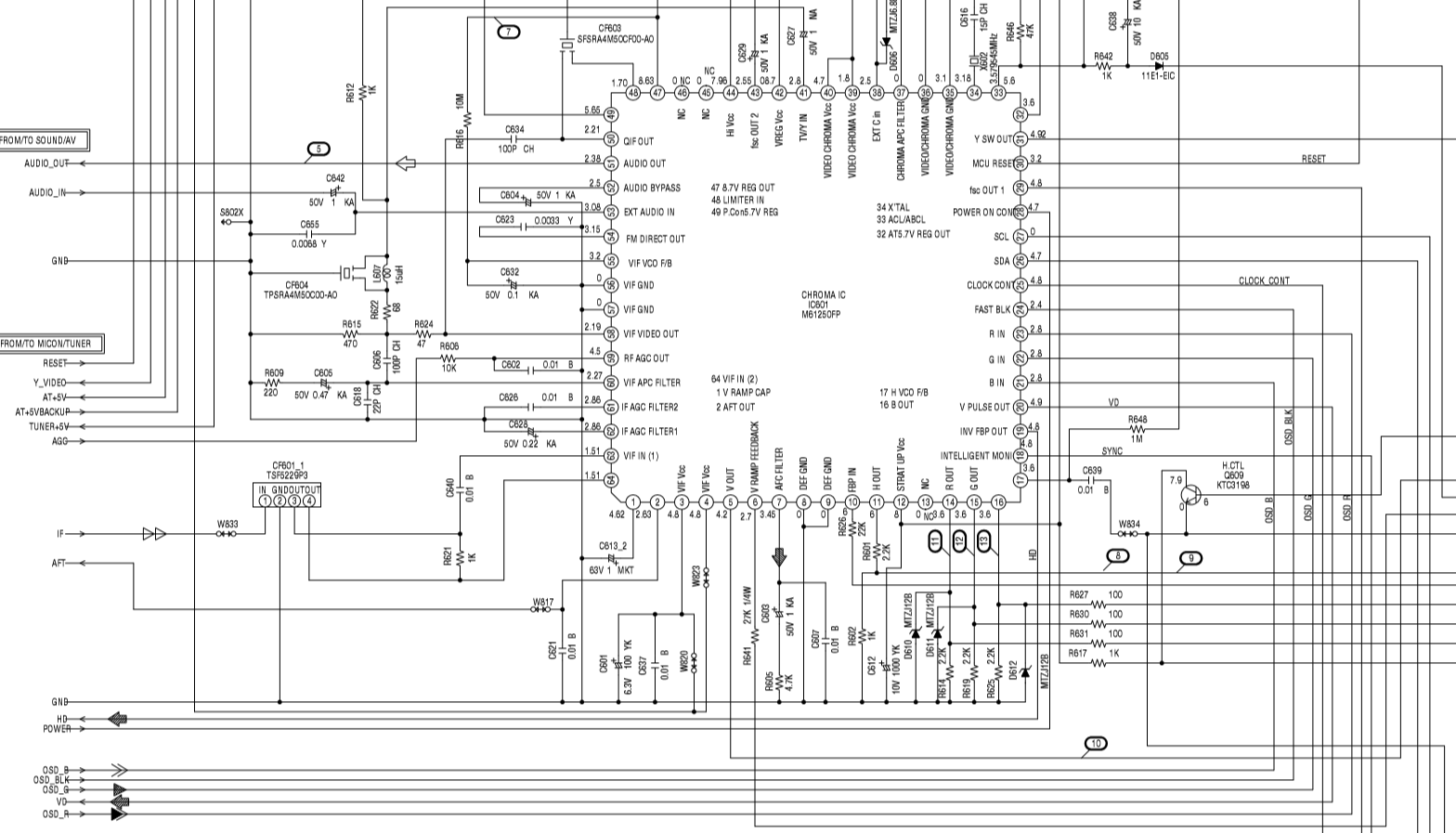
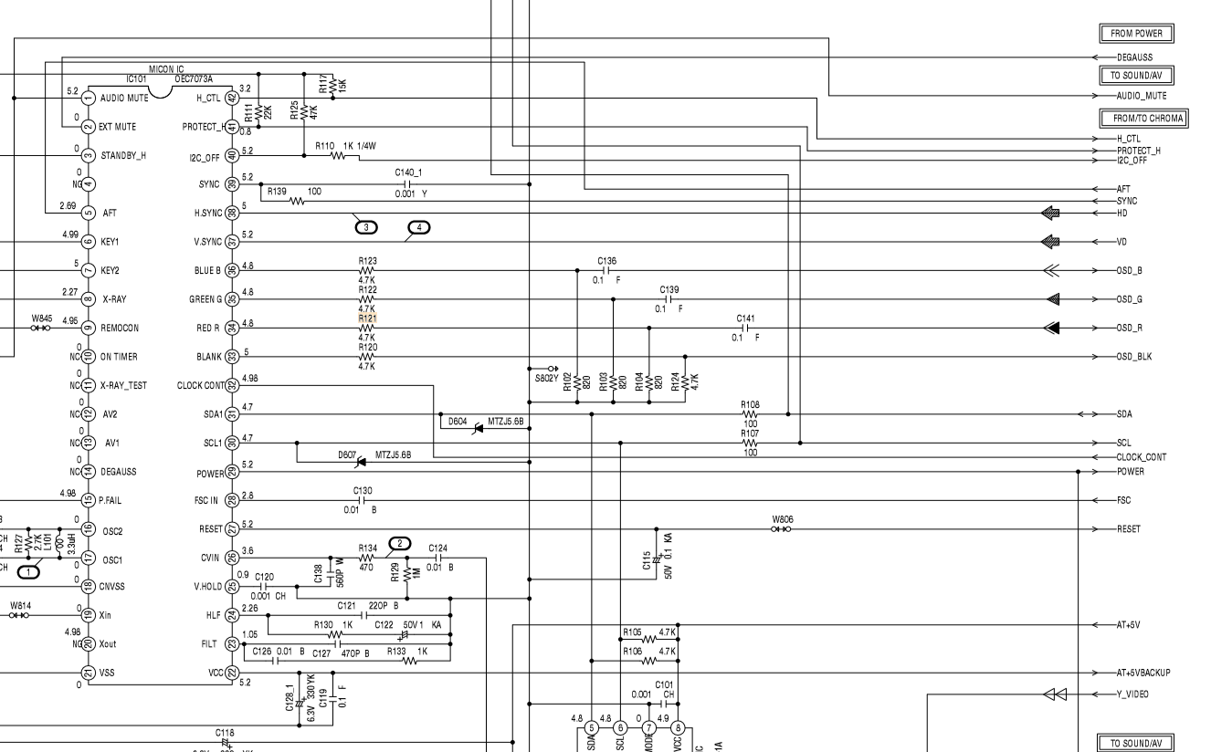
Hey everyone. I have a real nice 2003 model 20" Symphonic/Funai WF203 flat screen that only has composite in. I just found a fantastically detailed service manual and was looking it over. I'd like to be able to RGB mod the set, but I would settle for S-Video if I had to. From my limited knowledge, it appears the IC333 pins 29 (C) and 30 (Y) are unused and basically ripe for the taking. Only question is what do I need to do with the pin 61 (S-Video Input detect). What kind of signal would be expected on that pin to get the set to use the incoming signals on 29 and 30.
As far as RGB modding, I dont see any RGB input pins, only output. Would tapping into the output lines work? If so, what could I do about sync? I see some H and V sync related circuitry and pins, but have no clue what would be needed for injecting a sync signal there. If I tap into RGB outputs, could connecting sync into the composite port do the trick if I made the tv look at the correct video in? Any help would be greatly appreciated.


As far as RGB modding, I dont see any RGB input pins, only output. Would tapping into the output lines work? If so, what could I do about sync? I see some H and V sync related circuitry and pins, but have no clue what would be needed for injecting a sync signal there. If I tap into RGB outputs, could connecting sync into the composite port do the trick if I made the tv look at the correct video in? Any help would be greatly appreciated.
Re: TV RGB mod thread
Hello everyone!
This is my second run to RGB Mod world. I started with a Sony BA-5D chassis and the result was amazing, now i had the opportunity to buy another Sony TV, a KV-34FV15b, with a AA2W chassis.
Unfortunately, i can't apply the same mod from BA-5D to the AA2W chassis, but, fortunately, Zektor on post viewtopic.php?f=6&t=56155&start=2745 shared a pretty similar OSD circuit.
Following MarkOZLAD instruction I recalculate EXT RGB Inline and found 390Ω, for a 2.7kΩ OSD Inline resistor, am I correct?
For the blanking circuit, near the Jungle IC, there are 2 resistors in the schematic, R357* and R358*, as far can i understand, only R358* is present on the KV-34FV15b model and it is just a jumper, am i right? If it's true, probably i can use it as an connection point? Should I use a 430Ω for the EXT Blanking resistor?
Thanks for all the support!
 KV-34FV15b OSD diagram:

This is my second run to RGB Mod world. I started with a Sony BA-5D chassis and the result was amazing, now i had the opportunity to buy another Sony TV, a KV-34FV15b, with a AA2W chassis.
Unfortunately, i can't apply the same mod from BA-5D to the AA2W chassis, but, fortunately, Zektor on post viewtopic.php?f=6&t=56155&start=2745 shared a pretty similar OSD circuit.
Following MarkOZLAD instruction I recalculate EXT RGB Inline and found 390Ω, for a 2.7kΩ OSD Inline resistor, am I correct?
For the blanking circuit, near the Jungle IC, there are 2 resistors in the schematic, R357* and R358*, as far can i understand, only R358* is present on the KV-34FV15b model and it is just a jumper, am i right? If it's true, probably i can use it as an connection point? Should I use a 430Ω for the EXT Blanking resistor?
Thanks for all the support!
Spoiler
Re: TV RGB mod thread
Is there a guide somewhere in the thread for this?MarkOZLAD wrote:This looks like one I recently saw that was set in software to Digital RGB. You might be lucky. If not could use I2C serial intercept to set it to analog RGB.retrozar wrote:I came into possession of this unit awhile back and it only has a composite jack. Looking at the IC seems to show it is RGB modable.
This is a VCR combo set and it looks like it uses SVideo internally to connect the built in VCR to the TV. I was curious if i could possibly add SVideo too, as i see some Luma/Chroma pins on the IC. Anyone know which pins i should start with and how i would go about switching it on?
https://imgur.com/a/qCefHUc
Re: TV RGB mod thread
retrozar wrote:Is there a guide somewhere in the thread for this?MarkOZLAD wrote:This looks like one I recently saw that was set in software to Digital RGB. You might be lucky. If not could use I2C serial intercept to set it to analog RGB.retrozar wrote:I came into possession of this unit awhile back and it only has a composite jack. Looking at the IC seems to show it is RGB modable.
This is a VCR combo set and it looks like it uses SVideo internally to connect the built in VCR to the TV. I was curious if i could possibly add SVideo too, as i see some Luma/Chroma pins on the IC. Anyone know which pins i should start with and how i would go about switching it on?
https://imgur.com/a/qCefHUc
Check out this...
https://immerhax.com/?p=305
and this...
https://etim.net.au/tv-bus/
___________________________________________________
MarkOZLAD
OSD/External RGB Mux Diagram
OSD/External RGB Mux Resistor Value Table 0.7Vp-p : 0.5Vp-p
"Imagine toggle switch OSD modding a TV in 2019" - maxtherabbit
MarkOZLAD
OSD/External RGB Mux Diagram
OSD/External RGB Mux Resistor Value Table 0.7Vp-p : 0.5Vp-p
"Imagine toggle switch OSD modding a TV in 2019" - maxtherabbit
Re: TV RGB mod thread
MarkOZLAD wrote:
This looks like one I recently saw that was set in software to Digital RGB. You might be lucky. If not could use I2C serial intercept to set it to analog RGB.
Hey Mark, do you mind taking a quick look at the circuit above and let me know if its at least workable to o set up RGB on the outputs of the mux chip? If not, what about the Svideo idea that I had? Thanks in advance.
Re: TV RGB mod thread
Muxing with the outputs of the chip is not possible. You are moving into neck mod territory there.Josh128 wrote:MarkOZLAD wrote:
This looks like one I recently saw that was set in software to Digital RGB. You might be lucky. If not could use I2C serial intercept to set it to analog RGB.
Hey Mark, do you mind taking a quick look at the circuit above and let me know if its at least workable to o set up RGB on the outputs of the mux chip? If not, what about the Svideo idea that I had? Thanks in advance.
The S-Video mod may possible. Looks like you might have to ground pin 61 or something.
___________________________________________________
MarkOZLAD
OSD/External RGB Mux Diagram
OSD/External RGB Mux Resistor Value Table 0.7Vp-p : 0.5Vp-p
"Imagine toggle switch OSD modding a TV in 2019" - maxtherabbit
MarkOZLAD
OSD/External RGB Mux Diagram
OSD/External RGB Mux Resistor Value Table 0.7Vp-p : 0.5Vp-p
"Imagine toggle switch OSD modding a TV in 2019" - maxtherabbit

Re: TV RGB mod thread
Small bumpGeeDee wrote:(admittedly massive) Pics etc under the spoiler; I think I've got the entire gameplan down, I just want the green light that I'm on the right track from someone more experienced than I. Thanks in advance!
Spoiler
I have a few tubes I'd like to try this with, but I'm starting with a Memorex MT1197. Important pics below, but let me know if you need the whole manual!
-----------------------------------------------------------------------------------------
----------------------------------------------------------------------------------------------
If I have this right, I'm removing R120-R123 and adding jumpers in their place. Then I'm removing R102-R104, and replacing them with 750 resistors, since the original inline resisters I removed were 4,700 and there are no diodes between there and the IC. The 4,700 on R124 for blanking however stays, if I'm understanding the Mux mod circuit diagram correctly. Terminate RGB and Blanking with 75ohms to ground at the scart, then solder the other ends to the jumpers I made on R120-R123. There's already a 0.1uf cap leading out, so that wouldn't need to be replaced. The rest seems pretty cake in comparison...so long as I have the rest of that right
Let me know if I have anything backwards!
Re: TV RGB mod thread
GeeDee wrote:Small bumpGeeDee wrote:(admittedly massive) Pics etc under the spoiler; I think I've got the entire gameplan down, I just want the green light that I'm on the right track from someone more experienced than I. Thanks in advance!
Spoiler
I have a few tubes I'd like to try this with, but I'm starting with a Memorex MT1197. Important pics below, but let me know if you need the whole manual!
-----------------------------------------------------------------------------------------
----------------------------------------------------------------------------------------------
If I have this right, I'm removing R120-R123 and adding jumpers in their place. Then I'm removing R102-R104, and replacing them with 750 resistors, since the original inline resisters I removed were 4,700 and there are no diodes between there and the IC. The 4,700 on R124 for blanking however stays, if I'm understanding the Mux mod circuit diagram correctly. Terminate RGB and Blanking with 75ohms to ground at the scart, then solder the other ends to the jumpers I made on R120-R123. There's already a 0.1uf cap leading out, so that wouldn't need to be replaced. The rest seems pretty cake in comparison...so long as I have the rest of that right
Let me know if I have anything backwards!hoping to still get the green light on this before I break things out. I have these tubes out in a seperate garage atm, so Ill head out to grab the sets after I order anything extra that I might need. Thanks in advance!
Looks like a standard OSD mux.
You DO NOT "remove R120-R123 and add jumpers". R120-R123 are your OSD factory inline resistors, you need to keep them.
R102-R104 are the grounding resistors. The muxing is done here with the 750R (as per the table) with 75R.
If R102-R104 are through-hole use the twist method ala the 8-Bit Guy mod.
I suggest you look at your TV schematic and the mux diagram a bit more because you are a bit confused. Might be a good idea to check out my Sony BA-5D mod thread and look at the patterns in play.
___________________________________________________
MarkOZLAD
OSD/External RGB Mux Diagram
OSD/External RGB Mux Resistor Value Table 0.7Vp-p : 0.5Vp-p
"Imagine toggle switch OSD modding a TV in 2019" - maxtherabbit
MarkOZLAD
OSD/External RGB Mux Diagram
OSD/External RGB Mux Resistor Value Table 0.7Vp-p : 0.5Vp-p
"Imagine toggle switch OSD modding a TV in 2019" - maxtherabbit
Re: TV RGB mod thread
I understand it would be more or less a neck mod at that point. But if I can scope the levels of the R,G,B outputs, amplifying or attenuating the signals I tap into those traces might work if the sync is still passed from the composite in to the H and V ports on the neck, no?MarkOZLAD wrote: Muxing with the outputs of the chip is not possible. You are moving into neck mod territory there.
The S-Video mod may possible. Looks like you might have to ground pin 61 or something.

Re: TV RGB mod thread
We do not approve of neckboard mods here due to the dangers and health risks they have.
It bypasses all x-ray protection features.
Also you have no control over tuning the image.
It bypasses all x-ray protection features.
Also you have no control over tuning the image.
Re: TV RGB mod thread
I understand the concern of fiddling directly with the neckboard, but I fail to understand how simply tapping into the output traces of the muxing IC would bypass any kind of x-ray protection and be any more risky than tapping into any oher traces on that same muxing chip. This is not high potential circuitry at that point.Syntax wrote:We do not approve of neckboard mods here due to the dangers and health risks they have.
It bypasses all x-ray protection features.
Also you have no control over tuning the image.
Re: TV RGB mod thread
Because tapping directly to the neck board bypasses any X-Ray control the jungle has over the RGB signals.
Id do some more research before attempting, its really not worth it.
Find another set to mod.
Id do some more research before attempting, its really not worth it.
Find another set to mod.
Re: TV RGB mod thread
Syntax wrote:Because tapping directly to the neck board bypasses any X-Ray control the jungle has over the RGB signals.
Id do some more research before attempting, its really not worth it.
Find another set to mod.
10-4, I'll probably just do the S-Video mod on this one and leave RGB for a different set.
Re: TV RGB mod thread
SVideo should look pretty awesome compared to composite, I don't think you will be disappointed.
-
darknezz19
- Posts: 60
- Joined: Tue Oct 13, 2015 1:59 am
Re: TV RGB mod thread
https://imgur.com/a/pdVIXxx
Well if you guys ever loose osd on a mod like I did on this one, you can still control geometry if you're only option is neck tap. Interface with eeprom and lookup initial values in service manual. Find value and edit. Mine was an unknown chassis so had to play with data till I got the result. Also this crt rgb amp is okay.. but the one below I think will be better and will try that next.
http://members.optusnet.com.au/eviltim/ ... ga2arc.htm
https://imgur.com/a/nrhJG
The one above is pretty good, have to adjust r4 r8 and r12 to get higher voltages though. I think the other one has pots for all needed levels. The first one is a bit dim in os, but you can adjust brightness and contrast to get a good picture in mame.
-
MiteWiseacre
- Posts: 22
- Joined: Tue Jan 07, 2020 4:32 pm
Re: TV RGB mod thread
Trying to put a scart connection on my Toshiba a42 for consoles, still waiting on my female scart plug. I went ahead and wired in a MUX circuit and used some little clips to test connecting to a cheap SNES scart plug. Limited connectors so I only connected sync, ground, blanking and red. How weird is it I see all the colours, despite only using red?
I think I know what’s going on, not blanking and the composite is feeding through the luma on svideo rather than just syncing.. cheap cable isn’t grounded properly either
I think I know what’s going on, not blanking and the composite is feeding through the luma on svideo rather than just syncing.. cheap cable isn’t grounded properly either
Last edited by MiteWiseacre on Wed Feb 05, 2020 1:07 am, edited 2 times in total.
Re: TV RGB mod thread
Hello there, hope you can help me with my PVM, i have a SONY PVM 14N5U and it has not Component and I want to make a RGB MOD with Component and SCART, but i dont know what i need and where i have to solder, hope you can help me
here is the diagram https://drive.google.com/open?id=1nflff ... 0AMmpZNNrX
PLEASE I WANT TO MAKE A TUTORIAL FOR THIS MODEL HOPE YOU CAN HELP ME
here is the diagram https://drive.google.com/open?id=1nflff ... 0AMmpZNNrX
PLEASE I WANT TO MAKE A TUTORIAL FOR THIS MODEL HOPE YOU CAN HELP ME
Last edited by laikmike on Tue Feb 04, 2020 11:59 pm, edited 1 time in total.
Re: TV RGB mod thread
I've had a quick look at the schematic (your link is dead BTW)...laikmike wrote:Hello there, hope you can help me with my PVM, i have a SONY PVM 14N5U and it has not Component and I want to make a RGB MOD with Component and SCART, but i dont know what i need and where i have to solder, hope you can help me
here is the diagramhttps://s1.manualzz.com/store/data/0023 ... 15&p=86400
PLEASE I WANT TO MAKE A TUTORIAL FOR THIS MODEL HOPE YOU CAN HELP ME
Looks like there is a "Q Board" in the set. I would set about trying to fill in the missing components for analog RGB. Then I would add the switch S006 on the A Board.
___________________________________________________
MarkOZLAD
OSD/External RGB Mux Diagram
OSD/External RGB Mux Resistor Value Table 0.7Vp-p : 0.5Vp-p
"Imagine toggle switch OSD modding a TV in 2019" - maxtherabbit
MarkOZLAD
OSD/External RGB Mux Diagram
OSD/External RGB Mux Resistor Value Table 0.7Vp-p : 0.5Vp-p
"Imagine toggle switch OSD modding a TV in 2019" - maxtherabbit
Re: TV RGB mod thread
So i just need to get the rca and weld directly to the Q board??MarkOZLAD wrote:I've had a quick look at the schematic (your link is dead BTW)...laikmike wrote:Hello there, hope you can help me with my PVM, i have a SONY PVM 14N5U and it has not Component and I want to make a RGB MOD with Component and SCART, but i dont know what i need and where i have to solder, hope you can help me
here is the diagramhttps://s1.manualzz.com/store/data/0023 ... 15&p=86400
PLEASE I WANT TO MAKE A TUTORIAL FOR THIS MODEL HOPE YOU CAN HELP ME
Looks like there is a "Q Board" in the set. I would set about trying to fill in the missing components for analog RGB. Then I would add the switch S006 on the A Board.
EDIT: Sorry i will reupload the diagram
EDIT2: Here's the link https://drive.google.com/open?id=1nflff ... 0AMmpZNNrX
Re: TV RGB mod thread
BNC I would assume....laikmike wrote: So i just need to get the rca and weld directly to the Q board??
Looks like someone has done it before...
https://www.assembler-games.com/threads ... ess.70662/
Seems a fair bit of work to me.
___________________________________________________
MarkOZLAD
OSD/External RGB Mux Diagram
OSD/External RGB Mux Resistor Value Table 0.7Vp-p : 0.5Vp-p
"Imagine toggle switch OSD modding a TV in 2019" - maxtherabbit
MarkOZLAD
OSD/External RGB Mux Diagram
OSD/External RGB Mux Resistor Value Table 0.7Vp-p : 0.5Vp-p
"Imagine toggle switch OSD modding a TV in 2019" - maxtherabbit
Re: TV RGB mod thread
Thanks for the help, i already read that post, but i have some questions about it.MarkOZLAD wrote:BNC I would assume....laikmike wrote: So i just need to get the rca and weld directly to the Q board??
Looks like someone has done it before...
https://www.assembler-games.com/threads ... ess.70662/
Seems a fair bit of work to me.
Do i need all that components listed in the post?
how should i solder all that components
can i buy those component in a electronic store?
It might be dumb questions, but I'm noob in the RGB World, i just have the soldering skills
Thanks in advanced.
Re: TV RGB mod thread
It might be possible to hack the RGB instead.laikmike wrote: Do i need all that components listed in the post?
laikmike wrote: how should i solder all that components
can i buy those component in a electronic store?
It might be dumb questions, but I'm noob in the RGB World, i just have the soldering skills
Thanks in advanced.
___________________________________________________
MarkOZLAD
OSD/External RGB Mux Diagram
OSD/External RGB Mux Resistor Value Table 0.7Vp-p : 0.5Vp-p
"Imagine toggle switch OSD modding a TV in 2019" - maxtherabbit
MarkOZLAD
OSD/External RGB Mux Diagram
OSD/External RGB Mux Resistor Value Table 0.7Vp-p : 0.5Vp-p
"Imagine toggle switch OSD modding a TV in 2019" - maxtherabbit
Re: TV RGB mod thread
Is more easier to do that?MarkOZLAD wrote:It might be possible to hack the RGB instead.laikmike wrote: Do i need all that components listed in the post?
laikmike wrote: how should i solder all that components
can i buy those component in a electronic store?
It might be dumb questions, but I'm noob in the RGB World, i just have the soldering skills
Thanks in advanced.
How can i hack the RGB?
EDIT: There is any chance you could help by PM?
Re: TV RGB mod thread
laikmike wrote:Is more easier to do that?MarkOZLAD wrote:It might be possible to hack the RGB instead.laikmike wrote: Do i need all that components listed in the post?
laikmike wrote: how should i solder all that components
can i buy those component in a electronic store?
It might be dumb questions, but I'm noob in the RGB World, i just have the soldering skills
Thanks in advanced.
How can i hack the RGB?
EDIT: There is any chance you could help by PM?
If I were to treat this as a standard OSD mux candidate...
For RGB I would remove R308, R310 and R312 and feed 75 ohm terminated RGB into 1,000 or 1,1100 ohm resistors into the now empty, not grounded, pads of R308, R310 and R312.
EDIT: For blanking I would send 5V to a switch and the out of the switch into CN052 Pin 4.
___________________________________________________
MarkOZLAD
OSD/External RGB Mux Diagram
OSD/External RGB Mux Resistor Value Table 0.7Vp-p : 0.5Vp-p
"Imagine toggle switch OSD modding a TV in 2019" - maxtherabbit
MarkOZLAD
OSD/External RGB Mux Diagram
OSD/External RGB Mux Resistor Value Table 0.7Vp-p : 0.5Vp-p
"Imagine toggle switch OSD modding a TV in 2019" - maxtherabbit
Re: TV RGB mod thread
Let me see if I understand, In the A- Board there is empty Slots (ANALOG RGB) so I need to weld 1,000 or 1,1100 ohm to the empty A-Board Analog RGB Slots then weld from the IC301 R308,R310 and R312 and for blanking send 5v to a swtich from CN052 PIN4 the one named "BOX"???MarkOZLAD wrote: If I were to treat this as a standard OSD mux candidate...
For RGB I would remove R308, R310 and R312 and feed 75 ohm terminated RGB into 1,000 or 1,1100 ohm resistors into the now empty, not grounded, pads of R308, R310 and R312.
EDIT: For blanking I would send 5V to a switch and the out of the switch into CN052 Pin 4.
Re: TV RGB mod thread
Nope. Please re-read my commentslaikmike wrote:Let me see if I understand, In the A- Board there is empty Slots (ANALOG RGB) so I need to weld 1,000 or 1,1100 ohm to the empty A-Board Analog RGB Slots then weld from the IC301 R308,R310 and R312MarkOZLAD wrote: If I were to treat this as a standard OSD mux candidate...
For RGB I would remove R308, R310 and R312 and feed 75 ohm terminated RGB into 1,000 or 1,1100 ohm resistors into the now empty, not grounded, pads of R308, R310 and R312.
EDIT: For blanking I would send 5V to a switch and the out of the switch into CN052 Pin 4.
Yep.laikmike wrote: and for blanking send 5v to a swtich from CN052 PIN4 the one named "BOX"???
I offer one on one tutelage for $US100.laikmike wrote: There is any chance you could help by PM?
I have to limit the amount of help I give to people because I was making myself sick helping too many people do RGB mods.
___________________________________________________
MarkOZLAD
OSD/External RGB Mux Diagram
OSD/External RGB Mux Resistor Value Table 0.7Vp-p : 0.5Vp-p
"Imagine toggle switch OSD modding a TV in 2019" - maxtherabbit
MarkOZLAD
OSD/External RGB Mux Diagram
OSD/External RGB Mux Resistor Value Table 0.7Vp-p : 0.5Vp-p
"Imagine toggle switch OSD modding a TV in 2019" - maxtherabbit
Re: TV RGB mod thread
MarkOZLAD wrote:
If I were to treat this as a standard OSD mux candidate...
For RGB I would remove R308, R310 and R312 and feed 75 ohm terminated RGB into 1,000 or 1,1100 ohm resistors into the now empty, not grounded, pads of R308, R310 and R312.
EDIT: For blanking I would send 5V to a switch and the out of the switch into CN052 Pin 4.
EDIT: There are diodes on the RGB lines, this means you should use 1300 ohm resistors (not 1000 or 1100 as I said before)
___________________________________________________
MarkOZLAD
OSD/External RGB Mux Diagram
OSD/External RGB Mux Resistor Value Table 0.7Vp-p : 0.5Vp-p
"Imagine toggle switch OSD modding a TV in 2019" - maxtherabbit
MarkOZLAD
OSD/External RGB Mux Diagram
OSD/External RGB Mux Resistor Value Table 0.7Vp-p : 0.5Vp-p
"Imagine toggle switch OSD modding a TV in 2019" - maxtherabbit
Re: TV RGB mod thread
lol You are the man. Thanks for all your help to the retro community!MarkOZLAD wrote:
I have to limit the amount of help I give to people because I was making myself sick helping too many people do RGB mods.