Cool you got your rgb working but I always discharge my tv even with a bleeder resistor,better to be safe.evilsim wrote:I also never discharge the TV's, should I be doing this ? I'm very careful when working on these things.
TV RGB mod thread
-
Pikkon

- Posts: 129
- Joined: Tue May 26, 2015 6:25 am
- Location: Florida
Re: TV RGB mod thread
-
mikejmoffitt

- Posts: 629
- Joined: Fri Jan 08, 2016 7:26 am
- Location: Tokyo, Japan
Re: TV RGB mod thread
More details coming soon, but I've injected 240p RGB into a DTV34X NetTV. This one was very easy because not only did it have a Phillips jungle with an active second RGB input (for teletext/CC) but the entire jungle sub-board is easily removed without having to mess with the TV chassis at all. OSD still works.
I think it's time I parsed the thread and added some more links.
I think it's time I parsed the thread and added some more links.

-
cloudstrifer
- Posts: 12
- Joined: Wed Jul 13, 2016 4:48 pm
Re: TV RGB mod thread
Please, can someone help me?
I want to do RGB mod on this model kv-29fs140 (south america only?)
Look at SIFAGC/SCART pin 42.
Its possible? how?


I want to do RGB mod on this model kv-29fs140 (south america only?)
Look at SIFAGC/SCART pin 42.
Its possible? how?
Last edited by cloudstrifer on Fri Oct 20, 2017 11:57 am, edited 1 time in total.
-
mikejmoffitt
- Posts: 629
- Joined: Fri Jan 08, 2016 7:26 am
- Location: Tokyo, Japan
-
korpse413

- Posts: 193
- Joined: Mon Sep 15, 2014 11:23 pm
- Contact:
Re: TV RGB mod thread
mikejmoffitt wrote:More details coming soon, but I've injected 240p RGB into a DTV34X NetTV. This one was very easy because not only did it have a Phillips jungle with an active second RGB input (for teletext/CC) but the entire jungle sub-board is easily removed without having to mess with the TV chassis at all. OSD still works.
I think it's time I parsed the thread and added some more links.
This is incredible news! I picked up (hopefully) the same model earlier this year as seen in post viewtopic.php?f=6&t=60124. The OSD would list the frequency of horizontal/vertical and I was a bit disappointed the listed RGB Port its really VGA strictly 31kHz/60Hz. The interlacing on mine is pretty terrible with tons of jitter, most likely needs a nice recapping
P.S. - I might as well ask, but do you happen to have the remote control for your DTV34x set? I would love to get a model number or something to try and source one for mine ^^
-
cloudstrifer
- Posts: 12
- Joined: Wed Jul 13, 2016 4:48 pm
Re: TV RGB mod thread
Ok, i will try.mikejmoffitt wrote:Start with pins 77-80 maybe, they look related.
Thank you!
-
sparker599
- Posts: 6
- Joined: Fri Oct 13, 2017 7:17 am
Re: TV RGB mod thread
Thanks to MarkOZLAD and his post on the other thread viewtopic.php?p=1278413#p1278413 , I was able to mod my Sony KV-32fs13 and still have the OSD displayed while displaying RGB.
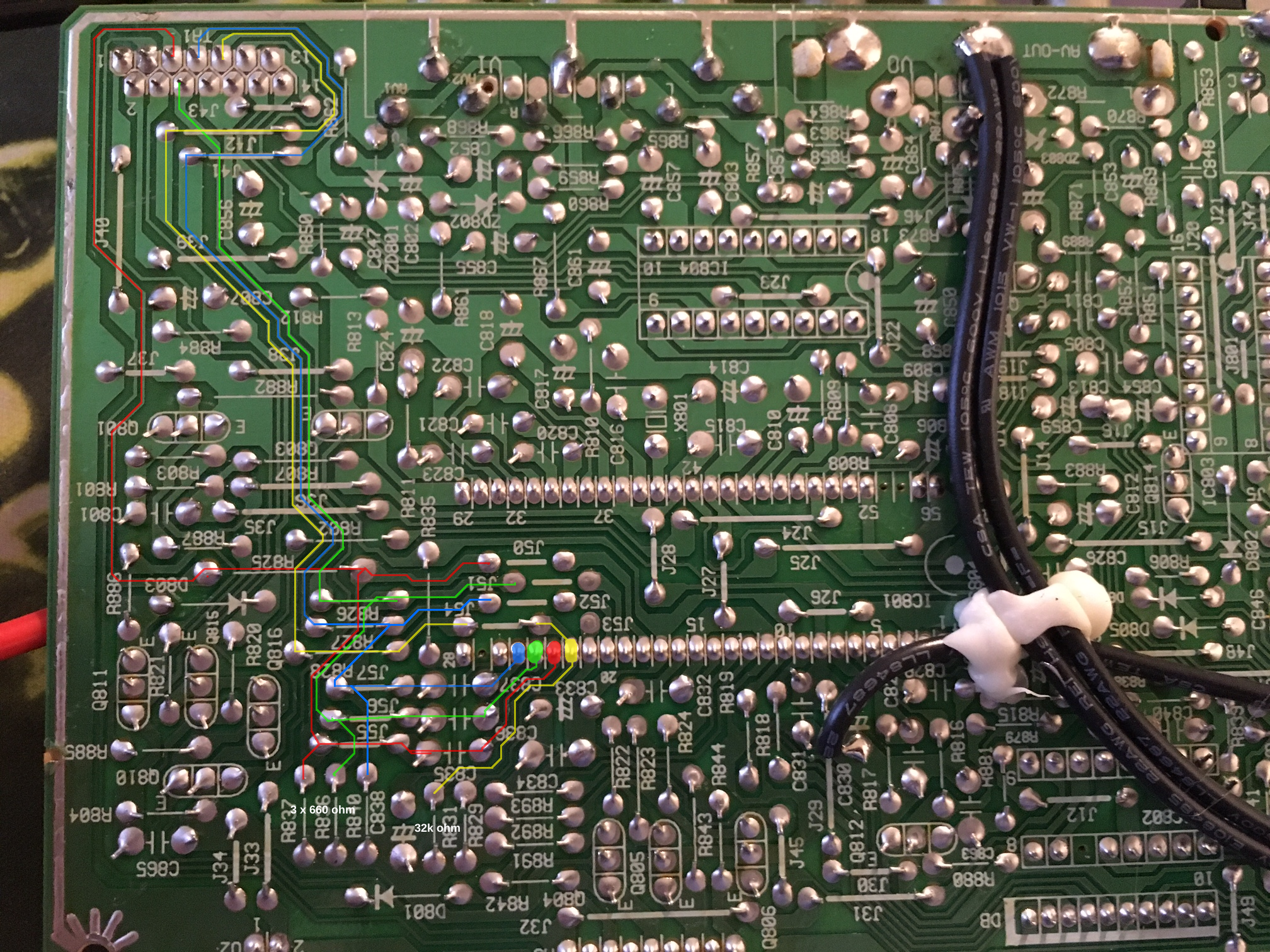
I found the caps just before the jungle's OSD RGB inputs, but those points where very small and on the bottom of the board. I wanted something larger and therfore easier to solder to, so I instead soldered the RGB lines to the legs of the OSD inline resistors facing away from the OSD chip. There is already a 680 ohm resistor on the board for termination to ground, so I didn't install my own termination resistors.
I only had to use 330 ohm resistors in series with the RGB inputs, solder those to the legs of the OSD inline resistors and install a switch and wires to switch between normal and 5v blanking.
The wire going to the blanking pin on the jungle IC broke off, so a hole had to be drilled on the side of the IC to be able to solder to it again.
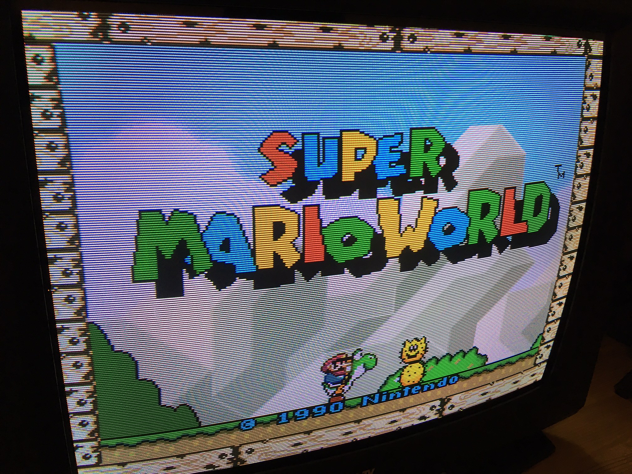
The RGB image is nice and bright, but the OSD is a bit difficult to see against a bright game (more difficult than in the first picture that MarkOZLAD posted). Against a black background, the OSD is a bit darker than it was before the mod, but still easily visible. Would it be a good idea to replace the OSD inline resistors with some lower-value ones to make the OSD brighter?
Pictures of my mod: https://drive.google.com/open?id=0B72ZO ... DZxNVZ5Wm8MarkOZLAD wrote: I am yet to find a TV that requires me to snip the OSD lines to inject RGB, This set was no different. I was able to find an unused port for external RGB input (in fact I used some holes for un-populated jumpers leading to this port) and injected the RGB there. The chip only has a single set of RGB inputs designed for OSD input. Therefore my RGB lines are sharing the same lines as the OSD, in fact with the board layout I am really just pumping the RGB directly into the caps that are before the Jungle's OSD RGB inputs with the OSD stiill connected to the same caps.
At first I had used the standard 75ohm termination to ground and the picture was terrible, dark and impossible to colour correct with the service menu...AND the OSD was washed out and barely useable. As I mentioned on the main RGB Mod thread I found this link. It said to use a 330Ohm resistor in line on the RGB lines and then have 580 ohm termination to ground. I was prettty desperate for any lead at this point. Long story short, this approach worked and I got the picture bright and the colours corrected.
The thing that makes this applicable to this thread is that after I added the 330 Ohm resistors to the RGB lines, the OSD was no longer washed out by the RGB input. It was very clear, had colour, and most importantly usable no matter what picture colours were showing.
I found the caps just before the jungle's OSD RGB inputs, but those points where very small and on the bottom of the board. I wanted something larger and therfore easier to solder to, so I instead soldered the RGB lines to the legs of the OSD inline resistors facing away from the OSD chip. There is already a 680 ohm resistor on the board for termination to ground, so I didn't install my own termination resistors.
I only had to use 330 ohm resistors in series with the RGB inputs, solder those to the legs of the OSD inline resistors and install a switch and wires to switch between normal and 5v blanking.
The wire going to the blanking pin on the jungle IC broke off, so a hole had to be drilled on the side of the IC to be able to solder to it again.
The RGB image is nice and bright, but the OSD is a bit difficult to see against a bright game (more difficult than in the first picture that MarkOZLAD posted). Against a black background, the OSD is a bit darker than it was before the mod, but still easily visible. Would it be a good idea to replace the OSD inline resistors with some lower-value ones to make the OSD brighter?
-
Issac Zachary
- Posts: 163
- Joined: Mon Oct 23, 2017 2:54 pm
Re: TV RGB mod thread
First, may I say that I'm really impressed with this thread and would like to thank everyone who has contributed to all this information! I think with what's in here I'll be able to do this mod and be gaming in RGB. Long live RGB! However, I thought I'd sign up to this forum and state my intentions in case I'm off by a few neurons.
I'm picking up a free Sony Trinitron Kv27v40 for RGB modding. From what I could research I found this page showing a Jungle chip on this particular TV:
https://www.manualslib.com/manual/48107 ... =35#manual
With close examination it looks a lot like this one from page 1 of this thread from Voultar (Thanks Voultar!):

So far, it looks like pins 30-32 are the RGB pins. I'm not sure yet where Sync is supposed to be connected or how (with capacitors/resistors.) But I've been reading up on Sync in an attempt to understand how to integrate it and see there are several types (over Luma, csying, etc.)
I can't wait to see my SNES in RGB! With that in mind I'll try really hard not to kill myself and was thinking of discharging through an incandescent light bulb for resistance purposes.
I'm picking up a free Sony Trinitron Kv27v40 for RGB modding. From what I could research I found this page showing a Jungle chip on this particular TV:
https://www.manualslib.com/manual/48107 ... =35#manual
With close examination it looks a lot like this one from page 1 of this thread from Voultar (Thanks Voultar!):
So far, it looks like pins 30-32 are the RGB pins. I'm not sure yet where Sync is supposed to be connected or how (with capacitors/resistors.) But I've been reading up on Sync in an attempt to understand how to integrate it and see there are several types (over Luma, csying, etc.)
I can't wait to see my SNES in RGB! With that in mind I'll try really hard not to kill myself and was thinking of discharging through an incandescent light bulb for resistance purposes.
-
evilsim

- Posts: 50
- Joined: Sat Jan 16, 2016 11:03 am
Re: TV RGB mod thread
Hey Issac, sync (clean, composite or Y sync) can usually be inserted by just connecting it to the AV1 port on your TV. For testing some people here solder a RCA male onto their sync line from their console and plug it directly into the AV port. Pin29 appears to be the YS/Blanking pin - you will need to pull this high to 5v for initial testing, then maybe lower voltages can be required with some tv's if it doesn't blank (and show the RGB picture).Issac Zachary wrote:I can't wait to see my SNES in RGB! With that in mind I'll try really hard not to kill myself and was thinking of discharging through an incandescent light bulb for resistance purposes.
Goodluck! Nothing beats RGB on a good CRT
-
MarkOZLAD
- Posts: 1040
- Joined: Thu May 18, 2017 12:39 pm
Re: TV RGB mod thread
Great news sparker599 !!!! Thank you for giving my method a shot, I'm really interested in it's success rate on other sets and I hate seeing OSD's snipped if they don't need to be.sparker599 wrote:Thanks to MarkOZLAD and his post on the other thread viewtopic.php?p=1278413#p1278413 , I was able to mod my Sony KV-32fs13 and still have the OSD displayed while displaying RGB.
Pictures of my mod: https://drive.google.com/open?id=0B72ZO ... DZxNVZ5Wm8
I found the caps just before the jungle's OSD RGB inputs, but those points where very small and on the bottom of the board. I wanted something larger and therfore easier to solder to, so I instead soldered the RGB lines to the legs of the OSD inline resistors facing away from the OSD chip. There is already a 680 ohm resistor on the board for termination to ground, so I didn't install my own termination resistors.
I only had to use 330 ohm resistors in series with the RGB inputs, solder those to the legs of the OSD inline resistors and install a switch and wires to switch between normal and 5v blanking.
The wire going to the blanking pin on the jungle IC broke off, so a hole had to be drilled on the side of the IC to be able to solder to it again.
The RGB image is nice and bright, but the OSD is a bit difficult to see against a bright game (more difficult than in the first picture that MarkOZLAD posted). Against a black background, the OSD is a bit darker than it was before the mod, but still easily visible. Would it be a good idea to replace the OSD inline resistors with some lower-value ones to make the OSD brighter?
With regards to the resistors on the OSD lines, I'm still learning about this method too. Have a read of what Syntax has done, he did alter the OSD side of the circuits so you might be right. Seems we want to beef up the OSD, tone down the external RGB or a combination of both.
My aim is always to have a usable OSD at the same time as RGB. If it isn't perfect, so be it.
___________________________________________________
MarkOZLAD
OSD/External RGB Mux Diagram
OSD/External RGB Mux Resistor Value Table 0.7Vp-p : 0.5Vp-p
"Imagine toggle switch OSD modding a TV in 2019" - maxtherabbit
MarkOZLAD
OSD/External RGB Mux Diagram
OSD/External RGB Mux Resistor Value Table 0.7Vp-p : 0.5Vp-p
"Imagine toggle switch OSD modding a TV in 2019" - maxtherabbit
-
MarkOZLAD
- Posts: 1040
- Joined: Thu May 18, 2017 12:39 pm
Re: TV RGB mod thread
Here's the diagram I've made for my modding method where we share the OSD lines with the external RGB we are inserting. I've left the Ohm values empty on the diagram but it seems 330 Ohms on the inline resistors is a good start. Termination resistors maybe 510 - 620 Ohm but all of this is still to be determined on a set by set basis and requires trial and error by the modder. Seems sometimes the termination resistors aren't even required. My method is to get RGB showing something and then using a breadboard/pots to experiment and find the right combinations. For Sony Trinitrons I'd be throwing 75 Ohm in line and 75 Ohm termination to ground and seeing what happens.
As with anything on this forum, nothing is guaranteed and the person modding the set needs to have patience, determination and resourcefulness to complete the job.
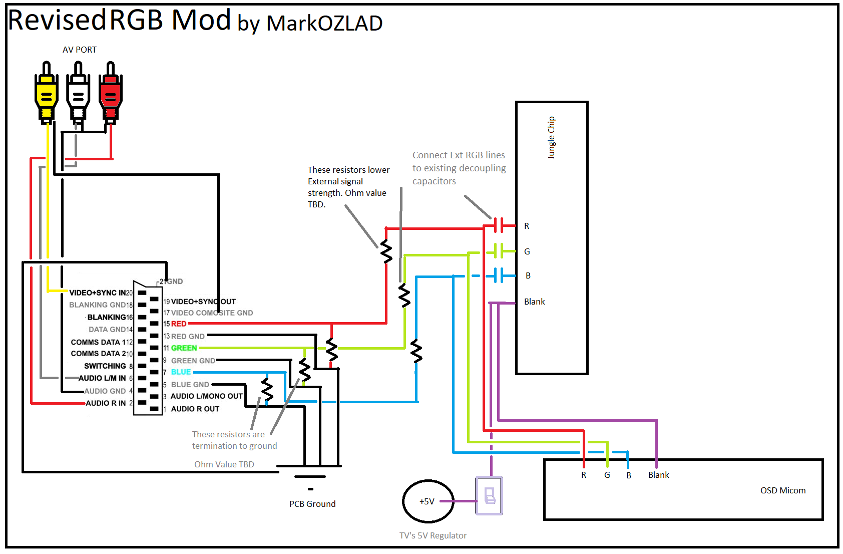
On the diagram I've shown blanking 5V coming from the internal 5V regulator but it could come from the Scart pin 16 blanking. Could build without a switch at all if you wanted. Also a 10K potentiometer on the blanking line, especially during testing, is a good idea to get the blanking voltages worked out.
Also for reference please read Syntax' posts for getting OSD and RGB working together. He uses a similar method but approaches it from the other end where he looks to beef up the OSD rather than toning down the external RGB. He's got great results on Sony sets......I'm pretty sure too that he's got an idea coming up that will blow this one into the weeds!
All constructive criticism welcome. Please post results of your work so we can make the method more prescriptive.
I hope this enables some people to get OSD working alongside the RGB.
oohh, almost forgot...
Big thankyou to 133Mhz on the RetroGames.cl forum for posting this thread about modding his NEX TV with generic Chinese chassis. Even though he did his with an OSD snip method his work coming up with the correct impedance for his set enabled me to progress my current mod and come up with this method. I'd be willing to bet that 133Mhz is better by miles than I am at this caper.
Another note.....
Typically when I mod I don't run lines directly to decoupling capacitors. I'm normally lucky enough to find external RGB inputs on the sets I've encountered. Before you try and solder to capacitors, try inspecting your TVs chassis for these inputs. They are often found as un-populated/unused headers/connectors nearby to the jungle IC. Sometimes these aren't even shown on the schematcis e.g. Connectors 1801 and 1802 I recently identified on a Sony AA-2D chassis. Check out the unused ports on your TV chassis visually and with the multimeter, if they connect to the decoupling capacitors for the Jungle's RGB pins you are in business.
As with anything on this forum, nothing is guaranteed and the person modding the set needs to have patience, determination and resourcefulness to complete the job.
On the diagram I've shown blanking 5V coming from the internal 5V regulator but it could come from the Scart pin 16 blanking. Could build without a switch at all if you wanted. Also a 10K potentiometer on the blanking line, especially during testing, is a good idea to get the blanking voltages worked out.
Also for reference please read Syntax' posts for getting OSD and RGB working together. He uses a similar method but approaches it from the other end where he looks to beef up the OSD rather than toning down the external RGB. He's got great results on Sony sets......I'm pretty sure too that he's got an idea coming up that will blow this one into the weeds!
All constructive criticism welcome. Please post results of your work so we can make the method more prescriptive.
I hope this enables some people to get OSD working alongside the RGB.
oohh, almost forgot...
Big thankyou to 133Mhz on the RetroGames.cl forum for posting this thread about modding his NEX TV with generic Chinese chassis. Even though he did his with an OSD snip method his work coming up with the correct impedance for his set enabled me to progress my current mod and come up with this method. I'd be willing to bet that 133Mhz is better by miles than I am at this caper.
Another note.....
Typically when I mod I don't run lines directly to decoupling capacitors. I'm normally lucky enough to find external RGB inputs on the sets I've encountered. Before you try and solder to capacitors, try inspecting your TVs chassis for these inputs. They are often found as un-populated/unused headers/connectors nearby to the jungle IC. Sometimes these aren't even shown on the schematcis e.g. Connectors 1801 and 1802 I recently identified on a Sony AA-2D chassis. Check out the unused ports on your TV chassis visually and with the multimeter, if they connect to the decoupling capacitors for the Jungle's RGB pins you are in business.
___________________________________________________
MarkOZLAD
OSD/External RGB Mux Diagram
OSD/External RGB Mux Resistor Value Table 0.7Vp-p : 0.5Vp-p
"Imagine toggle switch OSD modding a TV in 2019" - maxtherabbit
MarkOZLAD
OSD/External RGB Mux Diagram
OSD/External RGB Mux Resistor Value Table 0.7Vp-p : 0.5Vp-p
"Imagine toggle switch OSD modding a TV in 2019" - maxtherabbit
-
fandangos
- Posts: 144
- Joined: Tue Sep 18, 2012 3:48 am
Re: TV RGB mod thread
When taping 5v for 10k pot is there any risk of short circuit? Can I tap 5v directly from the psu of the tv board? or should I do it closer to the ic?
CapivaraGamer
http://capivaragamer.com.br
http://capivaragamer.com.br
-
MarkOZLAD
- Posts: 1040
- Joined: Thu May 18, 2017 12:39 pm
Re: TV RGB mod thread
A good option is to try and find the TVs 5V regulator and tap into the output pin.fandangos wrote:When taping 5v for 10k pot is there any risk of short circuit? Can I tap 5v directly from the psu of the tv board? or should I do it closer to the ic?
Even better, (credit to Syntax on this one) if your Scart pin 16 has a blanking voltage, which is standard, run it to the blanking pin.
___________________________________________________
MarkOZLAD
OSD/External RGB Mux Diagram
OSD/External RGB Mux Resistor Value Table 0.7Vp-p : 0.5Vp-p
"Imagine toggle switch OSD modding a TV in 2019" - maxtherabbit
MarkOZLAD
OSD/External RGB Mux Diagram
OSD/External RGB Mux Resistor Value Table 0.7Vp-p : 0.5Vp-p
"Imagine toggle switch OSD modding a TV in 2019" - maxtherabbit
-
fandangos
- Posts: 144
- Joined: Tue Sep 18, 2012 3:48 am
Re: TV RGB mod thread
EDIT: Success!!
Modded a GBT-2910 Gradiente TV with VTC3802 jungle IC.


img upload
Here are some pictures of the mod.
But I'm having a few problems.
I've built a board with 0.1uF caps and 75 ohms (2 150 resistors because I can't find 75ohm ones) resistors to GND.
The colors are too strong, and the image is too dark. Also, image is 1 cm to the right.
If I remove the resistors to GND, I get a image that's almost exploding.
So do I need to increase the value of the resistors?
Modded a GBT-2910 Gradiente TV with VTC3802 jungle IC.
img upload
Here are some pictures of the mod.
But I'm having a few problems.
I've built a board with 0.1uF caps and 75 ohms (2 150 resistors because I can't find 75ohm ones) resistors to GND.
The colors are too strong, and the image is too dark. Also, image is 1 cm to the right.
If I remove the resistors to GND, I get a image that's almost exploding.
So do I need to increase the value of the resistors?
CapivaraGamer
http://capivaragamer.com.br
http://capivaragamer.com.br
-
Syntax

- Posts: 1828
- Joined: Wed Aug 09, 2017 12:10 am
- Location: Australia
Re: TV RGB mod thread
Try putting 1k resistors inline on the rgb wires.
-
boliva
- Posts: 8
- Joined: Tue Oct 31, 2017 3:21 am
Re: TV RGB mod thread
Hi everyone, new member here. First of all I want to start by thanking for all of the contributions and seemingly endless stream of information on this subject, after spending many days reading on different sites I found this thread to be one of the most comprehensive and active sources on consumer CRT TV modding.
That being said, I would like to tap into your collective knowledge (and hopefully be able to feed it even further) by posting a few questions.
I got an old CRT TV (american, so no SCART input, only composite, s-video and YPbPr) which I want to repurpose on a custom built arcade style cabinet for use with emulators. After finding out it's possible to get native 15khz resolutions from a computers video card with the right software (which I already have working) I learned there are basically 2 ways for me to put a pixel perfect picture on tv screen:
1. by using a VGA to Component (YPbPr) transcoder, with the AA 9A60 being regarded as one of the best for this task
– or –
2. modding the TV to inject the signal directly into the RGB tube input.
Now, option 1 would be the shortest path, but also the most expensive, since a quality dedicated piece of hardware easily runs into the $100 range plus I would have to import it (not available in my country) which would add to the cost and time required to actually get it. Being a tinkerer and since cabinet build is a completely DIY project, I've decided to try approach #2 first. I also believe (albeit subjectively) that this route will in the end provide a superior image quality than by placing a transcoder in the middle.
My TV is a Sony Trinitron Wega model KV-25FS120 (KV-24FS120 in the US) (schematics here: http://www.archivotecnicosaurios.com/de ... rvicio.pdf).
Since I'll be using a PC to generate the image I don't have a SCART type of source, so my first question is if it's possible to directly tap into the RGB lines of the computers VGA and feed them to the TV via OSD hack. If so, what should I do with the HSync signal coming out from the video card? If I understand correctly what's commonly done in these mods is to use the composite or s-video inputs to feed the sync signal, would in this case work the same way?
My other question is regarding the original OSD. Originally this hack makes use of a mechanical switch to either enable the direct RGB input or the built in OSD (for menus and such), but a few users (namely KnuckleheadFlow and MarkOZLAD) have been able to mix both. Would this be possible under my desired setup, and would my TV set allow it?
It's worth noting that I don't have much experience with microelectronics, but I know the basics and can handle my way with a soldering iron. Also, a friend of mine which used to own a TV repair shop will be helping me along the way.
Once again thanks to all of you for the time you've put into this. My end goal is to place a female VGA connector on the back of my TV set.
-
nakedarthur

- Posts: 218
- Joined: Tue Jul 21, 2015 8:20 pm
Re: TV RGB mod thread
You can combine the Horizontal and Vertical sync coming out of the VGA into Composite Sync that the TV expects (via the Luma channel of the S-video input). I'm using this method with the two 1k resistors on my Sony KV-27S42 and GroovyMAME machine and it works great.boliva wrote:Since I'll be using a PC to generate the image I don't have a SCART type of source, so my first question is if it's possible to directly tap into the RGB lines of the computers VGA and feed them to the TV via OSD hack. If so, what should I do with the HSync signal coming out from the video card? If I understand correctly what's commonly done in these mods is to use the composite or s-video inputs to feed the sync signal, would in this case work the same way?
-
Syntax
- Posts: 1828
- Joined: Wed Aug 09, 2017 12:10 am
- Location: Australia
Re: TV RGB mod thread
Had a quick look but.boliva wrote:Hi everyone, new member here. First of all I want to start by thanking for all of the contributions and seemingly endless stream of information on this subject, after spending many days reading on different sites I found this thread to be one of the most comprehensive and active sources on consumer CRT TV modding.
That being said, I would like to tap into your collective knowledge (and hopefully be able to feed it even further) by posting a few questions.
I got an old CRT TV (american, so no SCART input, only composite, s-video and YPbPr) which I want to repurpose on a custom built arcade style cabinet for use with emulators. After finding out it's possible to get native 15khz resolutions from a computers video card with the right software (which I already have working) I learned there are basically 2 ways for me to put a pixel perfect picture on tv screen:
1. by using a VGA to Component (YPbPr) transcoder, with the AA 9A60 being regarded as one of the best for this task
– or –
2. modding the TV to inject the signal directly into the RGB tube input.
Now, option 1 would be the shortest path, but also the most expensive, since a quality dedicated piece of hardware easily runs into the $100 range plus I would have to import it (not available in my country) which would add to the cost and time required to actually get it. Being a tinkerer and since cabinet build is a completely DIY project, I've decided to try approach #2 first. I also believe (albeit subjectively) that this route will in the end provide a superior image quality than by placing a transcoder in the middle.
My TV is a Sony Trinitron Wega model KV-25FS120 (KV-24FS120 in the US) (schematics here: http://www.archivotecnicosaurios.com/de ... rvicio.pdf).
Since I'll be using a PC to generate the image I don't have a SCART type of source, so my first question is if it's possible to directly tap into the RGB lines of the computers VGA and feed them to the TV via OSD hack. If so, what should I do with the HSync signal coming out from the video card? If I understand correctly what's commonly done in these mods is to use the composite or s-video inputs to feed the sync signal, would in this case work the same way?
My other question is regarding the original OSD. Originally this hack makes use of a mechanical switch to either enable the direct RGB input or the built in OSD (for menus and such), but a few users (namely KnuckleheadFlow and MarkOZLAD) have been able to mix both. Would this be possible under my desired setup, and would my TV set allow it?
It's worth noting that I don't have much experience with microelectronics, but I know the basics and can handle my way with a soldering iron. Also, a friend of mine which used to own a TV repair shop will be helping me along the way.
Once again thanks to all of you for the time you've put into this. My end goal is to place a female VGA connector on the back of my TV set.
Internal OSD
No Teletext
No Component/RGB switch
Walk away......
cn301 is your best bet but that's going straight to the neck/tube.
-
lukilla
- Posts: 66
- Joined: Fri Apr 14, 2017 2:21 am
Re: TV RGB mod thread
There is the other method too. Vga>video amp>neck board 
https://www.facebook.com/groups/4445602 ... 917210832/
https://www.facebook.com/groups/4445602 ... 917210832/
-
MKL
- Posts: 453
- Joined: Wed Feb 02, 2005 9:33 pm
- Location: Pordenone, Italy
Re: TV RGB mod thread
A bad method as the automatic cutoff control is lost this way.lukilla wrote:There is the other method too. Vga>video amp>neck board
https://www.facebook.com/groups/4445602 ... 917210832/
-
buttersoft

- Posts: 377
- Joined: Sun Jul 24, 2016 7:49 am
Re: TV RGB mod thread
Which, as his eminence Tim tells us, can pull the HV out of regulation. Bad idea.MKL wrote:A bad method as the automatic cutoff control is lost this way.lukilla wrote:There is the other method too. Vga>video amp>neck board
https://www.facebook.com/groups/4445602 ... 917210832/
-
lukilla
- Posts: 66
- Joined: Fri Apr 14, 2017 2:21 am
Re: TV RGB mod thread
It works fine on the several televisions Hakero1 (he made the tutorial but it´s in spanish) and I have done, it´s more work but that´s it, you can even tune amplitude and gain for ultimate picture calibration no problem  :
:

-
takeshi385
- Posts: 26
- Joined: Sat May 07, 2011 11:10 pm
Re: TV RGB mod thread
It won't be until the weekend that I will get to finish this mod. I bought the kv 35v35 that was at my local thrift store, but after getting It home I noticed it had
two scratches that were about a mm deep in the glass of the screen. I spent a good amount of time using different compounds to polish them out. They are pretty much fully removed. It's not ideal, considering I didn't start with a perfect tv, but I have trouble finding the remnants of the scratch when the screen is off(have to use a flash light to bounce light off the uneven areas) and I can't find them at all when it is on so I guess it's perfect. For anyone who has scratches in their screen use polywatch glass polish.
two scratches that were about a mm deep in the glass of the screen. I spent a good amount of time using different compounds to polish them out. They are pretty much fully removed. It's not ideal, considering I didn't start with a perfect tv, but I have trouble finding the remnants of the scratch when the screen is off(have to use a flash light to bounce light off the uneven areas) and I can't find them at all when it is on so I guess it's perfect. For anyone who has scratches in their screen use polywatch glass polish.
-
lolitsevan
- Posts: 25
- Joined: Mon May 04, 2015 3:39 am
Re: TV RGB mod thread
I just finished a jvc c13710, and it looks surprisingly good. Composite is total shit but the rgb image is really clean, and I've only ever worked on sonys so comparing the shadow mask to ap grille is kinda interesting. My issue is that the screen is a little dim, I was wondering if lowering the resistance on the pulldown resistors might help brighten up the image? I'm currently using 75's for pulldown with nothing inline besides the .1uf caps. Also the screen looks greener than it should, I'm thinking if I open it up again I'll look for a pot to tweak for the green gun around the neckboard but if anyone has any other suggestions I'm open to them, the service menu is really limited on this set.
On a more interesting note, i picked up a little 9" sony kv-9pt50, and while I was looking at the datasheet for the JIC, I noticed it not only has digital inputs for RGB, but separate H and V sync, so I was wondering if this monitor would then be capable of CGA/15k VGA? 9" isn't really enough real estate to play on for me so I'm just looking to do something interesting with this one, the standard mod seems easy enough, just might have to try a few different voltage sources and I'm not sure which analog blanking pin I'm supposed to use, but I'm really interested in the digital RGB stuff.
Datasheet for the kv-9pt50 jungle ic here
-
boliva
- Posts: 8
- Joined: Tue Oct 31, 2017 3:21 am
Re: TV RGB mod thread
Hey again, thanks for all your quick responses.
A more general but related question, if I have no way but to inject the RGB signals into the tube would the OSD be permanently overridden meaning I would have no way to make adjustments to brightness/levels/etc (without the menus) unless I place a switch?
Cheers,
No way to do the OSD hack then?Syntax wrote: Had a quick look but.
Internal OSD
No Teletext
No Component/RGB switch
Walk away......
Would you care to elaborate a bit?Syntax wrote: cn301 is your best bet but that's going straight to the neck/tube.
Is that FB post yours? If so would you mind sharing your schematics? I'm totally OK with them being in spanish.lukilla wrote: There is the other method too. Vga>video amp>neck board
Any way to prevent that?buttersoft wrote: Which, as his eminence Tim tells us, can pull the HV out of regulation. Bad idea.
A more general but related question, if I have no way but to inject the RGB signals into the tube would the OSD be permanently overridden meaning I would have no way to make adjustments to brightness/levels/etc (without the menus) unless I place a switch?
Cheers,
-
Syntax
- Posts: 1828
- Joined: Wed Aug 09, 2017 12:10 am
- Location: Australia
Re: TV RGB mod thread
Bottom line.
You can't RGB mod your set without using a separate amp that bypasses the Jungle IC.
The bypassed signal is not monitored by the Jungle but the sync still is so hv should still have protection.
You can't RGB mod your set without using a separate amp that bypasses the Jungle IC.
The bypassed signal is not monitored by the Jungle but the sync still is so hv should still have protection.
-
boliva
- Posts: 8
- Joined: Tue Oct 31, 2017 3:21 am
Re: TV RGB mod thread
Ok so I guess that going with a transcoder box is a safer choice. Is the AA 9A60 good enough?Syntax wrote:Bottom line.
You can't RGB mod your set without using a separate amp that bypasses the Jungle IC.
The bypassed signal is not monitored by the Jungle but the sync still is so hv should still have protection.
-
buttersoft
- Posts: 377
- Joined: Sun Jul 24, 2016 7:49 am
Re: TV RGB mod thread
As i understand it, and i'm far from an expert, there's normally a feedback loop that controls the beam current passing from the cathodes through the tube vacuum to the anode, and this is controlled by the jungle chip. Without it, a scene that's overly bright will cause too much current to flow, and this drops the HV. The flyback is mostly fixed coils, and as it also controls the voltage for the horizontal output stage, picture geometry can distort.boliva wrote:Any way to prevent that?buttersoft wrote: Which, as his eminence Tim tells us, can pull the HV out of regulation. Bad idea.
These are Tim's words thus far. Perhaps lowering the resistance between anode and cathode (more current) would effectively mean the flyback can overload in trying to compensate. There would have to be more power running through it, doing this. Then again this would also lower the grid voltages, which would self-limit the current, so i'm not sure.
I can definitely say that having driven a neckboard directly you can do a few weird things if you try, like altering the cutoff voltages without meaning to.
-
lukilla
- Posts: 66
- Joined: Fri Apr 14, 2017 2:21 am
Re: TV RGB mod thread
Yeah that FB post is mine, I can point you to the amp schematics and tutorial if you wish. As for the regulation and circuit feedback stuff that will no longer be in effect, you shouldn´t have any problem as long as you keep the video signal below certain threshold which is usually waay higher than what you need or what your eyes can withstandboliva wrote:
Is that FB post yours? If so would you mind sharing your schematics? I'm totally OK with them being in spanish.lukilla wrote: There is the other method too. Vga>video amp>neck board
Any way to prevent that?buttersoft wrote: Which, as his eminence Tim tells us, can pull the HV out of regulation. Bad idea.
A more general but related question, if I have no way but to inject the RGB signals into the tube would the OSD be permanently overridden meaning I would have no way to make adjustments to brightness/levels/etc (without the menus) unless I place a switch?
Cheers,
As for a working OSD you will need to build one of the switching circuits or just put some rca sockets and plugs in there to make adjustments to the image size or geometry, which once you get right you wont have much reason to access anymore unless you want to use the tv for something else. You can´t adjust brightness and gama via osd anymore with this method, you do that on the amplifier, basically first time you need to tune the image very well using pots on the amp displaying calibration images, and when you are really happy with it under several lighting conditions you measure the pots resistances off circuit and match them with solid resistors.
-
buttersoft
- Posts: 377
- Joined: Sun Jul 24, 2016 7:49 am
Re: TV RGB mod thread
Is this in the CRT collective on FB? I'd be keen for a look at the specs too, i have a set i can't mod and want to. I'd like to learn more about the beam current limits and how they work. I realise the current will not be increased too much, but i've seen how easy it is to mess up the cutoff (which only lasts until you power the set down for 30secs, of course). I guess i'd just prefer to know that what i'm doing is safe, rather than presuming.lukilla wrote: Yeah that FB post is mine, I can point you to the amp schematics and tutorial if you wish.