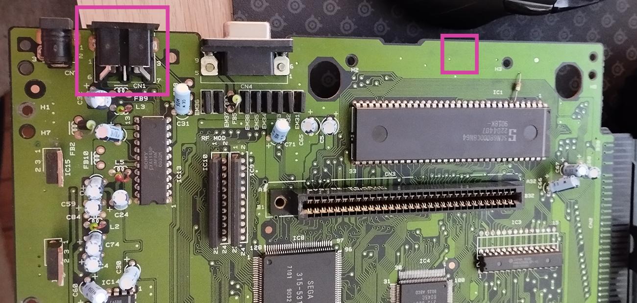
I want to install a triple bypass mod on a Japanese Mega Drive va4.
The problem is that I don’t have the space to solder a mini din 9 on the motherboard. I don’t have a rf module that I could remove to put the mini din.
Is it possible to remove the original din to scratch the motherboard at its slot and solder the mini din to it without any problem? Or is it better to scratch another part of the motherboard a little bit further (above the cartridge port as I circled it on my picture) and make a hole in the shell to put the rgb cable through?
I would keep the original AV port. Separate the L and R audio lines before they are mixed to mono. Cut either the composite video or composite sync pin and use that as the other audio channel.
The mini din sockets are prone to poor connections and will only give you problems.
Thank you for your help but to do this kind of thing I would need a step by step guide otherwise I won't be able to do what you are telling me.
It's a pity that we can't find more documentation about Japanese models on google