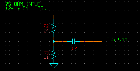
0.5Vp-p????
The datasheet for the TA1242N suggests 0.5Vp-p RGB input but I cannot be sure. Unfortunately the datasheet is in Chinese and being Australian my Chinese is quite poor....
I've also read in the TV RGB Mod thread that it is 0.5Vp-p but I don't know exactly why they are saying that.
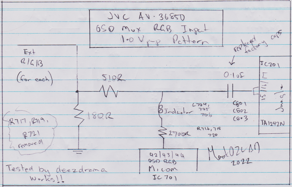
Let's examine the factory OSD circuitry. IC701 MN1874876JZX1 has 5V as it's Vdd. Thus I assume it's a 5V chip and will output 5V OSD. There factory voltage dividers on the OSD RGB uses a 2.7K ohm inline and 680 ohm to ground.
5V * 680 / (2700 + 680) = 1V (1.0059V)
I'm pretty sure I've seen other users that suggest it requires 1Vp-p....
I'm confused but let us first mod for 0.5Vp-p as a test and see how it goes. If it's no good we can revise.
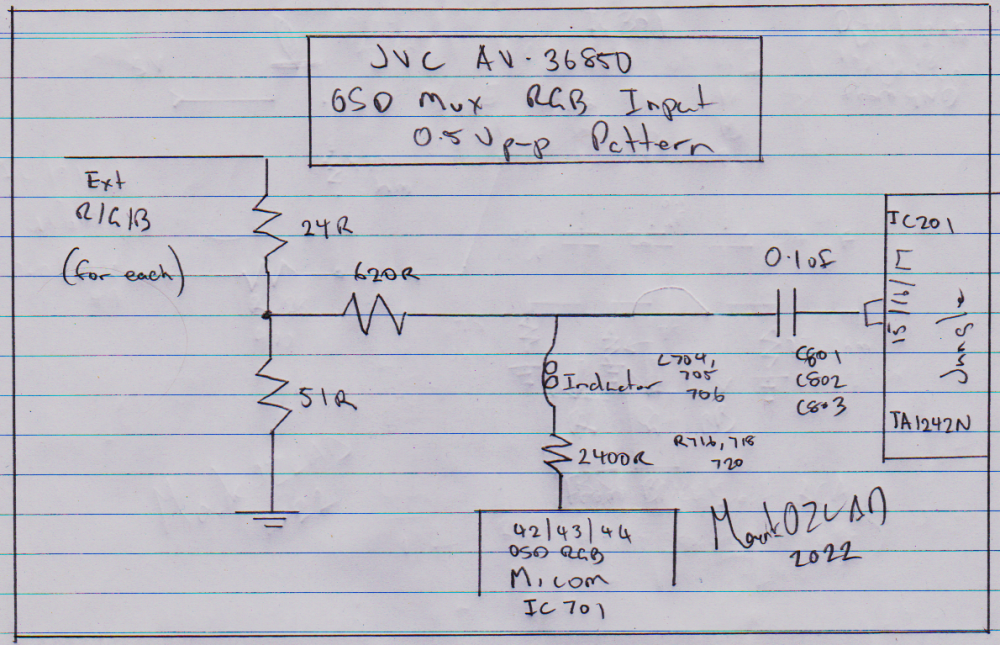
OSD Mux Resistor Calculation
Let's cheat here. The existing OSD grounding resistor is 680 ohm. Because we are using the 0.5Vp-p pattern for termination we will have a termination resistor of 51 ohm. 680 - 51 = 629 ohm. A 620 ohm mux resistor shoud be close enough.
This would result in an OSD voltage of..
5V * (620 + 51) / (2700 + (620 + 51)) = 1V (0.99525V close enough to 1V for my liking)
If it's good enough for the factory it's good enough for me
Physical Mod
Ok, here we go
1) Remove SMD resistors R717, R719, R721 (factory OSD "grounding" resistors)
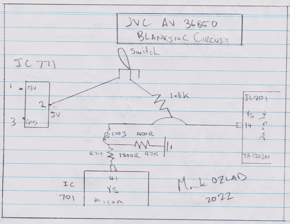
2) For blanking we want to go from a 5V source into a switch then into a 1.8K resistor and then onto jumper W019
3) For each of the RGB lines we want to bring the external RGB into a 24 ohm resistor and then 51 ohm to ground. Then for each run a line from between these two resistors onto the RGB jumpers into a 620 ohm resistor then onto their respective jumpers.
4) Replace caps C801, 802 and 803 with 0.1uF (104) ceramic caps


