Philips/mag PR1920 .... RGB Complete
Re: Philips/mag PR1920 .... RGB Complete
It’s possible it always shimmered. You probably weren’t looking at it critically prior to the mod.
___________________________________________________
MarkOZLAD
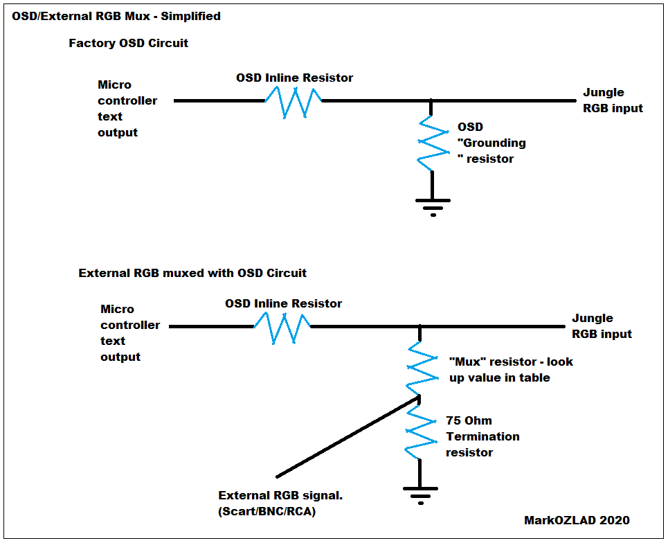
OSD/External RGB Mux Diagram
OSD/External RGB Mux Resistor Value Table 0.7Vp-p : 0.5Vp-p
"Imagine toggle switch OSD modding a TV in 2019" - maxtherabbit
MarkOZLAD
OSD/External RGB Mux Diagram
OSD/External RGB Mux Resistor Value Table 0.7Vp-p : 0.5Vp-p
"Imagine toggle switch OSD modding a TV in 2019" - maxtherabbit
Re: Philips/mag PR1920 .... RGB Complete
Its more like yellow colored pixels dancing around the green menu text but only when blanking switch is off and doesnt bother me at all because Its a dedicated rgb monitor now lol.MarkOZLAD wrote:It’s possible it always shimmered. You probably weren’t looking at it critically prior to the mod.
Thanks again!
Re: Philips/mag PR1920 .... RGB Complete
For anyone else who finds this thread I suggest using 270 ohm resistors in the place where 360 ohm are shown on the diagram.
___________________________________________________
MarkOZLAD
OSD/External RGB Mux Diagram
OSD/External RGB Mux Resistor Value Table 0.7Vp-p : 0.5Vp-p
"Imagine toggle switch OSD modding a TV in 2019" - maxtherabbit
MarkOZLAD
OSD/External RGB Mux Diagram
OSD/External RGB Mux Resistor Value Table 0.7Vp-p : 0.5Vp-p
"Imagine toggle switch OSD modding a TV in 2019" - maxtherabbit
Re: Philips/mag PR1920 .... RGB Complete
Love it.
I'd normally go with Mark OZ Lad like in the Wizard of Oz but I kinda like the way you say Mark "Oh Zee" LAD
The OZ is a reference to me being Australian.
Your implementation of the mod looks nice. Part of the reason I like to help others do these mods is because I always find it interesting and often learn something I can use in my own mods. In your implementation I was interested to see how you did the 75 ohm terminations.
___________________________________________________
MarkOZLAD
OSD/External RGB Mux Diagram
OSD/External RGB Mux Resistor Value Table 0.7Vp-p : 0.5Vp-p
"Imagine toggle switch OSD modding a TV in 2019" - maxtherabbit
MarkOZLAD
OSD/External RGB Mux Diagram
OSD/External RGB Mux Resistor Value Table 0.7Vp-p : 0.5Vp-p
"Imagine toggle switch OSD modding a TV in 2019" - maxtherabbit
Re: Philips/mag PR1920 .... RGB Complete
I wondered if you were Australian. Pronounciation noted for next shoutout I give ya LOL.MarkOZLAD wrote:Love it.
I'd normally go with Mark OZ Lad like in the Wizard of Oz but I kinda like the way you say Mark "Oh Zee" LAD
The OZ is a reference to me being Australian.
Your implementation of the mod looks nice. Part of the reason I like to help others do these mods is because I always find it interesting and often learn something I can use in my own mods. In your implementation I was interested to see how you did the 75 ohm terminations.
(Might need your brain on this 36" JVC 850 when I find time to mod it, Im going to replace a handful of caps on this Philips and also need to recap a pvm-1344q first to have room on the bench)
With the termination resistors... I was just trying to figure out what all I could solder in position first, had to lay the tube down flat to solder the grounding washer/tabs... Im sure there was a better way to do it but made things a little more difficult on myself by not using scart.
I wish we would of got scart here (did Australia have scart in 80s 90s?) But ive never owned a scart cable and invested into BNC cables at this point lol.
Anyway... Thanks again for the guidance!
Re: Philips/mag PR1920 .... RGB Complete
Happy to help with the JVC. Seems a popular one so worth documenting.
Can cover the theory a bit more if you like.
Can cover the theory a bit more if you like.
___________________________________________________
MarkOZLAD
OSD/External RGB Mux Diagram
OSD/External RGB Mux Resistor Value Table 0.7Vp-p : 0.5Vp-p
"Imagine toggle switch OSD modding a TV in 2019" - maxtherabbit
MarkOZLAD
OSD/External RGB Mux Diagram
OSD/External RGB Mux Resistor Value Table 0.7Vp-p : 0.5Vp-p
"Imagine toggle switch OSD modding a TV in 2019" - maxtherabbit
Re: Philips/mag PR1920 .... RGB Complete
That would be fantastic.MarkOZLAD wrote:Happy to help with the JVC. Seems a popular one so worth documenting.
Can cover the theory a bit more if you like.
As for the mux mod, I have a general idea of the process now, you use your table to estimate resistors needed, but in this philips case for example we removed grounding resistors also the factory resistors and replaced them with diodes.
Is adding diodes the preferred method since it would keep signal from getting back to the micon?
The 36" JVC i have is the 850 model which I havnt seen much on. Stabarz...the mod on crtreddit told me its the same micon/jungle as a toshiba set he did and that brightness and contrast will have to be adjusted by g2 and rgb sub brightness in service manual.
Still waiting on caps for the 1344q i have on the bench.
Probably wont open the jvc up for a few days or so untill i have bench room.
Re: Philips/mag PR1920 .... RGB Complete
I'm not sure why diodes are needed with the micro controller in the Phillips but in my experience they are required. I'm not an electrical engineer, a lot of my knowledge has come from trial an error.deezdrama wrote:That would be fantastic.MarkOZLAD wrote:Happy to help with the JVC. Seems a popular one so worth documenting.
Can cover the theory a bit more if you like.
As for the mux mod, I have a general idea of the process now, you use your table to estimate resistors needed, but in this philips case for example we removed grounding resistors also the factory resistors and replaced them with diodes.
Is adding diodes the preferred method since it would keep signal from getting back to the micon?
The 36" JVC i have is the 850 model which I havnt seen much on. Stabarz...the mod on crtreddit told me its the same micon/jungle as a toshiba set he did and that brightness and contrast will have to be adjusted by g2 and rgb sub brightness in service manual.
Still waiting on caps for the 1344q i have on the bench.
Probably wont open the jvc up for a few days or so untill i have bench room.
Can always install diodes to be safe if you like but it's not always practical to do so. The Phillips had a neat spot to install the diodes so it was an easy decision. For sets with SMD resistors and no jumpers on OSD it's not that simple.
The premise of the OSD mux mod is simple, you have an OSD from the factory that uses a voltage divider to drop 5V (or 3.3V in the case of the Philips) down to around 0.7V (scart "full on" voltage). We set up resistors so that there is still a voltage divider in place for the OSD but also allowing the external RGB to be inputted. The 75 Ohms termination and mux resistor becomes replace the "grounding" resistors we removed on OSD RGB.
This sums it up (diode not shown on this one)
___________________________________________________
MarkOZLAD
OSD/External RGB Mux Diagram
OSD/External RGB Mux Resistor Value Table 0.7Vp-p : 0.5Vp-p
"Imagine toggle switch OSD modding a TV in 2019" - maxtherabbit
MarkOZLAD
OSD/External RGB Mux Diagram
OSD/External RGB Mux Resistor Value Table 0.7Vp-p : 0.5Vp-p
"Imagine toggle switch OSD modding a TV in 2019" - maxtherabbit
Re: Philips/mag PR1920 .... RGB Complete
Thanks for this... I wondered why the grounding resistors were removed, It makes sense that they become the termination resistors.... So this is done for every mux mod then after this step the mux resistors value is calculated based off what the stock osd resistor values are and whether diodes are used right?MarkOZLAD wrote:I'm not sure why diodes are needed with the micro controller in the Phillips but in my experience they are required. I'm not an electrical engineer, a lot of my knowledge has come from trial an error.deezdrama wrote:That would be fantastic.MarkOZLAD wrote:Happy to help with the JVC. Seems a popular one so worth documenting.
Can cover the theory a bit more if you like.
As for the mux mod, I have a general idea of the process now, you use your table to estimate resistors needed, but in this philips case for example we removed grounding resistors also the factory resistors and replaced them with diodes.
Is adding diodes the preferred method since it would keep signal from getting back to the micon?
The 36" JVC i have is the 850 model which I havnt seen much on. Stabarz...the mod on crtreddit told me its the same micon/jungle as a toshiba set he did and that brightness and contrast will have to be adjusted by g2 and rgb sub brightness in service manual.
Still waiting on caps for the 1344q i have on the bench.
Probably wont open the jvc up for a few days or so untill i have bench room.
Can always install diodes to be safe if you like but it's not always practical to do so. The Phillips had a neat spot to install the diodes so it was an easy decision. For sets with SMD resistors and no jumpers on OSD it's not that simple.
The premise of the OSD mux mod is simple, you have an OSD from the factory that uses a voltage divider to drop 5V (or 3.3V in the case of the Philips) down to around 0.7V (scart "full on" voltage). We set up resistors so that there is still a voltage divider in place for the OSD but also allowing the external RGB to be inputted. The 75 Ohms termination and mux resistor becomes replace the "grounding" resistors we removed on OSD RGB.
This sums it up (diode not shown on this one)
Re: Philips/mag PR1920 .... RGB Complete
You got it
___________________________________________________
MarkOZLAD
OSD/External RGB Mux Diagram
OSD/External RGB Mux Resistor Value Table 0.7Vp-p : 0.5Vp-p
"Imagine toggle switch OSD modding a TV in 2019" - maxtherabbit
MarkOZLAD
OSD/External RGB Mux Diagram
OSD/External RGB Mux Resistor Value Table 0.7Vp-p : 0.5Vp-p
"Imagine toggle switch OSD modding a TV in 2019" - maxtherabbit
Re: Philips/mag PR1920 .... RGB Complete
Got the little rgb modded philips all buttoned up and upstairs perched ontop of my panasonic BT1950 broadcast monitor which is the best CRT I own and this little philips compares well!MarkOZLAD wrote:You got it
If I didnt have any pvm's or pro monitors I would be super content with an rgb muxed consumer set!

But ive noticed on images with alot of one solid color on the screen i get these diagonal lines which I assume is noise or interference?

Any ideas what could be causing this?
The leads I used to run signals to the bnc connectors were from small gauge ribbon I always used for installing rgb mod boards into nintendos.... I think 26awg
I also ran rgb leads bundled together to the port in chassis board, and ran ground and blanking together to the board.
This small awg wire is another reason I ran bnc connectors to the front to keep the leads short.
Any ideas?
Edit.... Heres some nice comparison pics of this rgb modded set next to an 800tvl panasonic broadcast monitor incase anyones interested.
https://www.reddit.com/r/crtgaming/comm ... urce=share
Re: Philips/mag PR1920 .... RGB Complete
Wow they are really pronounced interference lines.
Do your wires go anywhere near the flyback or AC?
Do your wires go anywhere near the flyback or AC?
___________________________________________________
MarkOZLAD
OSD/External RGB Mux Diagram
OSD/External RGB Mux Resistor Value Table 0.7Vp-p : 0.5Vp-p
"Imagine toggle switch OSD modding a TV in 2019" - maxtherabbit
MarkOZLAD
OSD/External RGB Mux Diagram
OSD/External RGB Mux Resistor Value Table 0.7Vp-p : 0.5Vp-p
"Imagine toggle switch OSD modding a TV in 2019" - maxtherabbit
Re: Philips/mag PR1920 .... RGB Complete
Not by the flyback but right under the power circuit.MarkOZLAD wrote:Wow they are really pronounced interference lines.
Do your wires go anywhere near the flyback or AC?
I wonder if covering it with aluminum tape would shield it at all. Maybe i should just run them closer to the front panel.
Re: Philips/mag PR1920 .... RGB Complete
If you do wrap it in aluminium tape as a shield I suggest you ground the shield.deezdrama wrote: Not by the flyback but right under the power circuit.
I wonder if covering it with aluminum tape would shield it at all. Maybe i should just run them closer to the front panel.
No idea if it would work, interested to see result.
___________________________________________________
MarkOZLAD
OSD/External RGB Mux Diagram
OSD/External RGB Mux Resistor Value Table 0.7Vp-p : 0.5Vp-p
"Imagine toggle switch OSD modding a TV in 2019" - maxtherabbit
MarkOZLAD
OSD/External RGB Mux Diagram
OSD/External RGB Mux Resistor Value Table 0.7Vp-p : 0.5Vp-p
"Imagine toggle switch OSD modding a TV in 2019" - maxtherabbit
Re: Philips/mag PR1920 .... RGB Complete
That will do it!deezdrama wrote:right under the power circuit.
If you can't use shielded wire, try running the TV with the case open and experiment with wire placement until the interference is gone.
Old VGA cables are an easy source of mini coax if you want to upgrade your wiring.
Re: Philips/mag PR1920 .... RGB Complete
Yep, I've used them too. I use shielded wire on all my mods. Requires some planning for how to connect shields etc but worth it for worry free installation.matt wrote:Old VGA cables are an easy source of mini coax if you want to upgrade your wiring.
___________________________________________________
MarkOZLAD
OSD/External RGB Mux Diagram
OSD/External RGB Mux Resistor Value Table 0.7Vp-p : 0.5Vp-p
"Imagine toggle switch OSD modding a TV in 2019" - maxtherabbit
MarkOZLAD
OSD/External RGB Mux Diagram
OSD/External RGB Mux Resistor Value Table 0.7Vp-p : 0.5Vp-p
"Imagine toggle switch OSD modding a TV in 2019" - maxtherabbit
Re: Philips/mag PR1920 .... RGB Complete
Yeah, Im pissed I didnt think of doing that. So is it necessary to ground the shielding strands on each end with a cutup vga cable?matt wrote:That will do it!deezdrama wrote:right under the power circuit.
If you can't use shielded wire, try running the TV with the case open and experiment with wire placement until the interference is gone.
Old VGA cables are an easy source of mini coax if you want to upgrade your wiring.
Re: Philips/mag PR1920 .... RGB Complete
I've seen so many different opinions on this.deezdrama wrote:Yeah, Im pissed I didnt think of doing that. So is it necessary to ground the shielding strands on each end with a cutup vga cable?
I generally do but I use the shields as my ground wires.
___________________________________________________
MarkOZLAD
OSD/External RGB Mux Diagram
OSD/External RGB Mux Resistor Value Table 0.7Vp-p : 0.5Vp-p
"Imagine toggle switch OSD modding a TV in 2019" - maxtherabbit
MarkOZLAD
OSD/External RGB Mux Diagram
OSD/External RGB Mux Resistor Value Table 0.7Vp-p : 0.5Vp-p
"Imagine toggle switch OSD modding a TV in 2019" - maxtherabbit
-
SweetStrat57
- Posts: 13
- Joined: Sun Sep 25, 2022 3:15 am
Re: Philips/mag PR1920 .... RGB Complete
Hello gentlemen. I'm new to the forum and have just acquired this tv. I've been trying to follow along with the thread and deezdrama's youtube video. But there are a few things I'm lost on. First, and I know this is a dumb question, but what kind of switch should I use (SPST, SPDT, etc.) and how is it wired to the header board installed at 0219? Second, I didn't see any mention of the 150 Ohm and 2.7K resistors shown here I circled in green. Forgive my ignorance. I've built guitar effects pedals in the past, but those skills are pretty basic compared to television circuitry. Any help would be appreciated!

-
SweetStrat57
- Posts: 13
- Joined: Sun Sep 25, 2022 3:15 am
Re: Philips/mag PR1920 .... RGB Complete
SweetStrat57 wrote:Hello gentlemen. I'm new to the forum and have just acquired this tv. I've been trying to follow along with the thread and deezdrama's youtube video. But there are a few things I'm lost on. First, and I know this is a dumb question, but what kind of switch should I use (SPST, SPDT, etc.) and how is it wired to the header board installed at 0219? Second, I didn't see any mention of the 150 Ohm and 2.7K resistors shown here I circled in green. Forgive my ignorance. I've built guitar effects pedals in the past, but those skills are pretty basic compared to television circuitry. Any help would be appreciated!
I don’t know why this message is just being posted, but I got this sorted out weeks ago. Thanks for all the help here, though.
-
YellowBirdAZ
- Posts: 3
- Joined: Sun Nov 27, 2022 6:02 pm
Re: Philips/mag PR1920 .... RGB Complete
I acquired a Philips/Magnavox TS2774 C101 in hopes of RGB modding it. I've done a Sony (a well-documented model), so I have a little experience.
I wasn't able to find much documentation on the Philips, but I saw enough that I expected the jungle and the micro controller to be the same as the PR1920 (SAA5543PS and TDA8846). This turned out to be correct. However, the layout of the board is sufficiently different that I feel slightly over my head. I was hoping to basically just copy the mod described for the PR1920, but it isn't going to be that straight-forward.
The TS2774 is an F8 chassis. I was finally able to find some documentation about this chassis. I reproduced some of it below and highlighted the RGB and blanking lines.

https://imgur.com/a/0L0Hhvi
I guess as a starting point I am having trouble seeing where the inline OSD resistors are. Are they they 3675, 3676 and 3677 (for R, G and B)? Those look like 150 ohm resistors.
If anyone can chime in, I'd really appreciate any help.
EDIT: I just saw this got approved. I already did this mod since posting this. I detailed it on the main RGB mod thread.
I wasn't able to find much documentation on the Philips, but I saw enough that I expected the jungle and the micro controller to be the same as the PR1920 (SAA5543PS and TDA8846). This turned out to be correct. However, the layout of the board is sufficiently different that I feel slightly over my head. I was hoping to basically just copy the mod described for the PR1920, but it isn't going to be that straight-forward.
The TS2774 is an F8 chassis. I was finally able to find some documentation about this chassis. I reproduced some of it below and highlighted the RGB and blanking lines.
https://imgur.com/a/0L0Hhvi
I guess as a starting point I am having trouble seeing where the inline OSD resistors are. Are they they 3675, 3676 and 3677 (for R, G and B)? Those look like 150 ohm resistors.
If anyone can chime in, I'd really appreciate any help.
EDIT: I just saw this got approved. I already did this mod since posting this. I detailed it on the main RGB mod thread.