I am a complete beginner when It comes to this modding CRT's so please be patient... I have no Idea what I'm talking about so any help would be greatly appreciated. I have already opened up and discharged my CRT and taken everything out. My next step was figuring out how to correctly mod this thing. I found this reddit post:
https://www.reddit.com/r/crtgaming/comm ... _list_for/
It was exactly what I needed! Finally, a guide to modding my exact CRT model. If possible it would be great if someone could confirm if everything looks good so I can rest easy. I do trust this redditor and they have been extremely helpful so I don't want to offend them. The instructions are in the reddit post. I know that this person's mod works, but I just want a second opinion to make sure that this is the best way to do it. (just to be safe)
I just don't want my TV slowly being damaged over time without me noticing that I did something wrong.
I can provide pictures of my TV if needed. Thanks for any responses!!
RGB Modding A Sony Trinitron KV-13M10
RGB Modding A Sony Trinitron KV-13M10
Last edited by TetsuoXLI on Fri Jan 07, 2022 2:18 am, edited 1 time in total.
Re: RGB Modding A Sony Trinitron KV-13M10
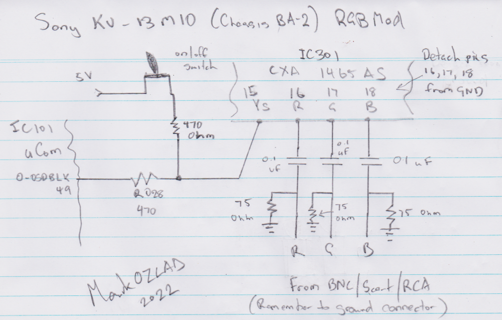
Assuming that the Analog RGB pins 16,17 and 18 are enabled it should be a matter of making sure they are disconnected from ground and then sending 75 ohm terminated RGB via 0.1uF capacitors into them.
Blanking should be 1.0V or greater into pin 15 Ys. Probably ok to just send 5V.
Sync/audio into AV input.
If for some reason the Analog RGB input isn't enabled you will need to do an I2C serial hack to override the internal registers of the CXA1465AS.
No need for mux or switch for OSD as it goes into the jungle's digital RGB pins.
___________________________________________________
MarkOZLAD
OSD/External RGB Mux Diagram
OSD/External RGB Mux Resistor Value Table 0.7Vp-p : 0.5Vp-p
"Imagine toggle switch OSD modding a TV in 2019" - maxtherabbit
MarkOZLAD
OSD/External RGB Mux Diagram
OSD/External RGB Mux Resistor Value Table 0.7Vp-p : 0.5Vp-p
"Imagine toggle switch OSD modding a TV in 2019" - maxtherabbit
Re: RGB Modding A Sony Trinitron KV-13M10
Thanks for the reply!
So everything looks okay? Sorry I'm still learning so I don't fully understand.
So from what I can tell from your reply:
I need to add capacitors (not exactly sure how to do that)
The blanking looks good
Sync and audio look good
And I don't quite understand the part about the OSD. I don't need a switch?
(if anyone else replies, talk to me like I'm 10 years old haha)
As long as the mod will turn out well and no components of the TV will slowly be damaged over time I am content!
Re: RGB Modding A Sony Trinitron KV-13M10
Well you'll need to add 75 ohm resistors to ground and capacitors onto the RGB circuits sonmewhere. Some people do this at the scart port or BNC connectors or whatever you use. Some people make up little circuit boards.TetsuoXLI wrote: I need to add capacitors (not exactly sure how to do that)
You will want to install a simple on off switch for blanking. You don't need to worry about the OSD at all, it enters the jungle on seperate pins.TetsuoXLI wrote: And I don't quite understand the part about the OSD. I don't need a switch?
This is not an OSD hijack mod, it is an "unused RGB input" mod.
___________________________________________________
MarkOZLAD
OSD/External RGB Mux Diagram
OSD/External RGB Mux Resistor Value Table 0.7Vp-p : 0.5Vp-p
"Imagine toggle switch OSD modding a TV in 2019" - maxtherabbit
MarkOZLAD
OSD/External RGB Mux Diagram
OSD/External RGB Mux Resistor Value Table 0.7Vp-p : 0.5Vp-p
"Imagine toggle switch OSD modding a TV in 2019" - maxtherabbit
Re: RGB Modding A Sony Trinitron KV-13M10
So I just need to :
1. Solder resistors between the RGB wires and their respective BNC jack
2. Solder a capacitor between my ground wires and their respective BNC jack.
1. Solder resistors between the RGB wires and their respective BNC jack
2. Solder a capacitor between my ground wires and their respective BNC jack.
Last edited by TetsuoXLI on Fri Jan 07, 2022 3:02 am, edited 1 time in total.
Re: RGB Modding A Sony Trinitron KV-13M10
This should be close.
You could use the Reddit dude's Blanking circuit design if you like as it is known good.
You could use the Reddit dude's Blanking circuit design if you like as it is known good.
___________________________________________________
MarkOZLAD
OSD/External RGB Mux Diagram
OSD/External RGB Mux Resistor Value Table 0.7Vp-p : 0.5Vp-p
"Imagine toggle switch OSD modding a TV in 2019" - maxtherabbit
MarkOZLAD
OSD/External RGB Mux Diagram
OSD/External RGB Mux Resistor Value Table 0.7Vp-p : 0.5Vp-p
"Imagine toggle switch OSD modding a TV in 2019" - maxtherabbit
Re: RGB Modding A Sony Trinitron KV-13M10
Um, technically it was my mistake because I designed the mod for David.TetsuoXLI wrote: I also watched this youtube video:
https://www.youtube.com/watch?v=NkpSBK3g-gA&t=134s
This video goes over a mistake that this YouTuber made in their mod. (Watch up to 00:02:06) I just want someone to look at the instructions found in this reddit post and make sure that this same problem won't happen.
___________________________________________________
MarkOZLAD
OSD/External RGB Mux Diagram
OSD/External RGB Mux Resistor Value Table 0.7Vp-p : 0.5Vp-p
"Imagine toggle switch OSD modding a TV in 2019" - maxtherabbit
MarkOZLAD
OSD/External RGB Mux Diagram
OSD/External RGB Mux Resistor Value Table 0.7Vp-p : 0.5Vp-p
"Imagine toggle switch OSD modding a TV in 2019" - maxtherabbit
Re: RGB Modding A Sony Trinitron KV-13M10
Oh I see! Sorry I wasn't trying to point that out. I had no idea. Props though for designing that mod! It looked great!
Last edited by TetsuoXLI on Fri Jan 07, 2022 4:12 am, edited 1 time in total.
Re: RGB Modding A Sony Trinitron KV-13M10
I was thinking of making my own diagram to confirm that I understand yours. That way you know if I have misunderstood something. (hopefully I can complete it in just a little while)
EDIT: I just realized that the original reddit instructions had the resistors and capacitors in it and I completely overlooked it!
EDIT: I just realized that the original reddit instructions had the resistors and capacitors in it and I completely overlooked it!
Re: RGB Modding A Sony Trinitron KV-13M10
Here is my drawing:
https://imgur.com/a/tXJdZlq
So from what I can understand, I can choose to either use the original reddit instructions for the switch or use yours and they will both work?
Also, how exactly do I connect capacitors in the middle of a wire. Do I just bend the two wires of the capacitor in opposite directions and solder wires to them? And for the resistors, do I also just solder?
Haha I'm such a noob!
Re: RGB Modding A Sony Trinitron KV-13M10
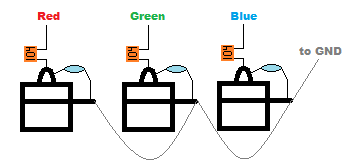
You have the 75 ohm resistors in the wrong place. The RGB lines have to have 75 ohm resistors between them and ground. Look more closely at my diagram.
The Grounds on the BNC connectors need to be connected directly to gound.
A lot of people connect the BNC connectors to ground and then connect the signal line of the BNC to a 75 ohm resistor and the other leg to the BNC ground
TetsuoXLI wrote:So from what I can understand, I can choose to either use the original reddit instructions for the switch or use yours and they will both work?
Go ahead and use the blanking design from the Reddit user. It's tried and tested.
Pretty much.TetsuoXLI wrote:Also, how exactly do I connect capacitors in the middle of a wire. Do I just bend the two wires of the capacitor in opposite directions and solder wires to them? And for the resistors, do I also just solder?
Once you understand what needs to be done, the layout of the TV chassis and parts, you'll work out how to install.
___________________________________________________
MarkOZLAD
OSD/External RGB Mux Diagram
OSD/External RGB Mux Resistor Value Table 0.7Vp-p : 0.5Vp-p
"Imagine toggle switch OSD modding a TV in 2019" - maxtherabbit
MarkOZLAD
OSD/External RGB Mux Diagram
OSD/External RGB Mux Resistor Value Table 0.7Vp-p : 0.5Vp-p
"Imagine toggle switch OSD modding a TV in 2019" - maxtherabbit
Re: RGB Modding A Sony Trinitron KV-13M10
Something like this
___________________________________________________
MarkOZLAD
OSD/External RGB Mux Diagram
OSD/External RGB Mux Resistor Value Table 0.7Vp-p : 0.5Vp-p
"Imagine toggle switch OSD modding a TV in 2019" - maxtherabbit
MarkOZLAD
OSD/External RGB Mux Diagram
OSD/External RGB Mux Resistor Value Table 0.7Vp-p : 0.5Vp-p
"Imagine toggle switch OSD modding a TV in 2019" - maxtherabbit
Re: RGB Modding A Sony Trinitron KV-13M10
I get it now. I can still use the three individual ground wires for each BNC connector right? Should I use heat shrink so wires don't touch each other?
Thank you very much for helping me out! I'm really excited to get started.
Sorry for all of my inexperience
Here are the parts I am planning to buy, could you possibly look over them and make sure they all look good?
Ribbon cables:
https://www.amazon.com/gp/product/B07P7 ... WFVG7&th=1
1k ohm Resisotor:
https://www.amazon.com/EDGELEC-Resistor ... HJ1ZQ&th=1
BNC jacks:
https://www.amazon.com/gp/product/B07FB ... mid=&psc=1
0.1 uF Capacitors:
https://www.amazon.com/gp/product/B08B3 ... smid=&th=1
75 ohm Resistors
https://www.amazon.com/gp/product/B07QK ... 90N86&th=1
Any recommendations for a switch?
Re: RGB Modding A Sony Trinitron KV-13M10
Yes.TetsuoXLI wrote:I get it now. I can still use the three individual ground wires for each BNC connector right?
If they look like they could possibly short out against something.TetsuoXLI wrote:Should I use heat shrink so wires don't touch each other?
Something that can be mounted in a round hole so you can install by drill.TetsuoXLI wrote:Any recommendations for a switch?
___________________________________________________
MarkOZLAD
OSD/External RGB Mux Diagram
OSD/External RGB Mux Resistor Value Table 0.7Vp-p : 0.5Vp-p
"Imagine toggle switch OSD modding a TV in 2019" - maxtherabbit
MarkOZLAD
OSD/External RGB Mux Diagram
OSD/External RGB Mux Resistor Value Table 0.7Vp-p : 0.5Vp-p
"Imagine toggle switch OSD modding a TV in 2019" - maxtherabbit
Re: RGB Modding A Sony Trinitron KV-13M10
Again, thanks for all the help!
Re: RGB Modding A Sony Trinitron KV-13M10
Another question:
For the capacitors, does the positive side face the BNC connector?
For the capacitors, does the positive side face the BNC connector?
Re: RGB Modding A Sony Trinitron KV-13M10
The capacitors you have ordered do not have a positive or a negative.
___________________________________________________
MarkOZLAD
OSD/External RGB Mux Diagram
OSD/External RGB Mux Resistor Value Table 0.7Vp-p : 0.5Vp-p
"Imagine toggle switch OSD modding a TV in 2019" - maxtherabbit
MarkOZLAD
OSD/External RGB Mux Diagram
OSD/External RGB Mux Resistor Value Table 0.7Vp-p : 0.5Vp-p
"Imagine toggle switch OSD modding a TV in 2019" - maxtherabbit
Re: RGB Modding A Sony Trinitron KV-13M10
I see. Thanks!
Re: RGB Modding A Sony Trinitron KV-13M10
https://imgur.com/a/yuqPlbs
Does this look right?
Also, Is the ribbon cable I bought the right one? (the link is above in a previous post) The wires seem reallly small so I just want to double check.
Does this look right?
Also, Is the ribbon cable I bought the right one? (the link is above in a previous post) The wires seem reallly small so I just want to double check.
Re: RGB Modding A Sony Trinitron KV-13M10
Picture looks good.
I don’t use ribbon cable so I don’t know. Should be fine though.
I don’t use ribbon cable so I don’t know. Should be fine though.
___________________________________________________
MarkOZLAD
OSD/External RGB Mux Diagram
OSD/External RGB Mux Resistor Value Table 0.7Vp-p : 0.5Vp-p
"Imagine toggle switch OSD modding a TV in 2019" - maxtherabbit
MarkOZLAD
OSD/External RGB Mux Diagram
OSD/External RGB Mux Resistor Value Table 0.7Vp-p : 0.5Vp-p
"Imagine toggle switch OSD modding a TV in 2019" - maxtherabbit