In an attempt to make an DIY Amiga SCART cable I came across that issue with the different sync levels not only seen in an Amiga. The Amiga outputs TTL (5V peak) that needs to be converted to 75 Ohms sync (1V peak as I understand). The general approach seems to include an resistor in series, 470 Ohms in case of the Amiga.
However in some thread on Shmups a reputable member said that this is a hack (Can't remember who and where, doesn't matter).
I'm trying to understand how the theory behind this works, could you help me with that?
The main issue is that we're talking about an AC circuit with impedance, not DC we're calculations are pretty easy.
As far as I understand that resistor causes a voltage drop. Since it's a resistor its resistance is is not dependent on the frequency. The voltage dropped is dependent on the current, which is determined by the total resistance and the voltage of the circuit - which isn't easily calculated since the resistance of the sink is variable depending on the frequency (aka 75 Ohm impedance). So how do you come up with a specific value for the resistor? And what are the effects of this resistor on the signal?
Additionally why is there no voltage divider circuit used?
Converting TTL to 75Ohms - the theory
-
gordon-creAtive
- Posts: 67
- Joined: Sat Jul 22, 2017 8:41 am
- Location: Emerald Hill Zone

Re: Converting TTL to 75Ohms - the theory
The resistor value is determined by the voltage present on the RGBS input pins when the correct value resistor is used. If you want ~.7V peak to peak, you select the inline resistor value that gives you that. This may vary due to different current draws on different displays, but is usually fairly standard. As for the voltage divider, some setup do parallel a resistor to ground, sometimes its a 75 ohm resistor. 
Re: Converting TTL to 75Ohms - the theory
In general the TTL CSYNC signal will be a "digital" signal, thus sharp edges, so it makes no "real" sense to talk about AC and frequency, as with sharp edges, frequency goes towards infinity (everything is of course approximations).
In general you want output resistance to be as close to 0 as possible, and input resistance as high as possible to avoid high current draws, which will otherwise complicate it all.
Anyway, the 470 Ohm resistor and the 75 Ohm terminating resistor creates a voltage divider, so with the above resistors you end up with a ~0.7Vpp signal at the input terminal, meaning over the terminating resistor. The input resistance of the sync side is generally much higher than the 75 Ohm, so the current drawn from the 75 Ohm will be much higher than the input circuit current draw, and thus you can neglect that. If you wanted to be "specific" you would need to measure input and output resistance and change your calculations, however this doesnt make sense, because the input resistance is "of course" specified so this is not an issue. Having a voltage buffer, and use a opamp circuit could of course be an idea (if such circuit isnt already present in the Amiga, or whatever output buffer circuit that might exist) to avoid excessive current draw on the output circuit of the CSYNC circuit, again, usually not something you need to take into account, but doing it of course doesnt hurt except for whatever delays you start introducing (which will also be negligible)...

Re: Converting TTL to 75Ohms - the theory
With sync, swing is not so much of an issue I think.
With RGB sometimes a voltage divider is not enough, you need pull up resistors for the correct signal "swing" else colors will be missing certain levels.
With RGB sometimes a voltage divider is not enough, you need pull up resistors for the correct signal "swing" else colors will be missing certain levels.
Re: Converting TTL to 75Ohms - the theory
Gordon-creative,
When you connect the Amiga's sync signal to the composite video input of a TV set (or whatever device) you are making a circuit. The 75 ohm impedance is just a resistor in practice, as it's got to be 75 ohms between 50 Hz and 10 MHz. Here is the circuit.
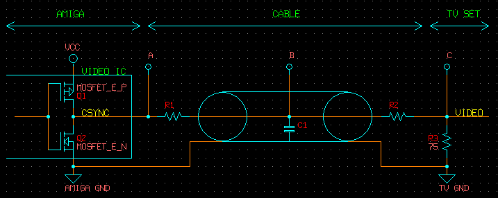
Assume R1 and R2 = 0 ohms for the moment. If that is the case then nodes A, B, C are equal. Then the CSYNC output is high, current will flow through Q1 then R3 to ground. You won't see 5V p-p across R3 because there is parasitic resistance in Q1, but the signal will still be greater than desired.
The easy solution is to put a series resistor between the sync output and TV input. This forms a voltage divider and attenuates the signal. You could put it before the cable (R1) or after the cable (R2). I also drew a capacitor C1 which represents cable capacitance. This is the capacitance between every conductor in the cable.
If you put the series resistor the R1 position you will have increased the source impedance of the signal by that amount before it enters the cable. This make it more susceptible to interference from other signals. On the other hand, the amplitude of the signal inside the cable (node B) is low so it couples less to other signals in the cable. This is essential if you are sharing the cable with an audio signal as a TTL sync signal will murder it via capacitive coupling.
In the case of 15 KHz video, you can get away with anything, so putting a resistor before the cable is OK. TTL signals are bad for cables in general because the swing is huge and the impedance is poorly defined. The series resistor fixes the swing, but raises the source impedance even further. It's OK for the Amiga, with 15 KHz video, you can get away with anything. Putting the resistor after the cable is generally better for the integrity of the sync signal itself.
The technically correct way to do it is to put another resistor to ground (call it R4), after R1, but before the cable, the value chosen so it would make R1//R4 = 75 ohms. Don't do this though as it requires even more current from the sync output.
BTW, CMOS logic levels from the sync output are not unconditionally 5 Vpp. It's depends on the ability of the the video IC's sync output to source current. It may well be 3 Vpp once you load it with 600 ohms. Also, 75 ohm sync is 0.3 Vpp. The 1 Vpp number is for sync (0.3) plus luma (0.7). It doesn't hurt much to increase the sync amplitude though, better to be too much that too little. I think 470 ohms is a good value to use.
When you connect the Amiga's sync signal to the composite video input of a TV set (or whatever device) you are making a circuit. The 75 ohm impedance is just a resistor in practice, as it's got to be 75 ohms between 50 Hz and 10 MHz. Here is the circuit.
Assume R1 and R2 = 0 ohms for the moment. If that is the case then nodes A, B, C are equal. Then the CSYNC output is high, current will flow through Q1 then R3 to ground. You won't see 5V p-p across R3 because there is parasitic resistance in Q1, but the signal will still be greater than desired.
The easy solution is to put a series resistor between the sync output and TV input. This forms a voltage divider and attenuates the signal. You could put it before the cable (R1) or after the cable (R2). I also drew a capacitor C1 which represents cable capacitance. This is the capacitance between every conductor in the cable.
If you put the series resistor the R1 position you will have increased the source impedance of the signal by that amount before it enters the cable. This make it more susceptible to interference from other signals. On the other hand, the amplitude of the signal inside the cable (node B) is low so it couples less to other signals in the cable. This is essential if you are sharing the cable with an audio signal as a TTL sync signal will murder it via capacitive coupling.
In the case of 15 KHz video, you can get away with anything, so putting a resistor before the cable is OK. TTL signals are bad for cables in general because the swing is huge and the impedance is poorly defined. The series resistor fixes the swing, but raises the source impedance even further. It's OK for the Amiga, with 15 KHz video, you can get away with anything. Putting the resistor after the cable is generally better for the integrity of the sync signal itself.
The technically correct way to do it is to put another resistor to ground (call it R4), after R1, but before the cable, the value chosen so it would make R1//R4 = 75 ohms. Don't do this though as it requires even more current from the sync output.
BTW, CMOS logic levels from the sync output are not unconditionally 5 Vpp. It's depends on the ability of the the video IC's sync output to source current. It may well be 3 Vpp once you load it with 600 ohms. Also, 75 ohm sync is 0.3 Vpp. The 1 Vpp number is for sync (0.3) plus luma (0.7). It doesn't hurt much to increase the sync amplitude though, better to be too much that too little. I think 470 ohms is a good value to use.