
Preface
Gradius III for SNES is more than just a port of the arcade original. Due to the szenic rearrangement on the one hand, and a dash of special features and small tweaks, the SNES version is a worthwhile title on its own right. For a long time, however, this otherwise great ensemble was – according to many – tarnished by one drop of bitterness: considerable slowdown. Some conjecture this would be ascribed to half-baked programming, because the developers weren't really familiar with the hardware yet due to the early release date. Others assume the slowdowns to be intentional, or at least approved, with the purpose to more closely resemble the arcade original, or to cushion difficulty spikes during crowded sections of gameplay.
The SA-1 patch
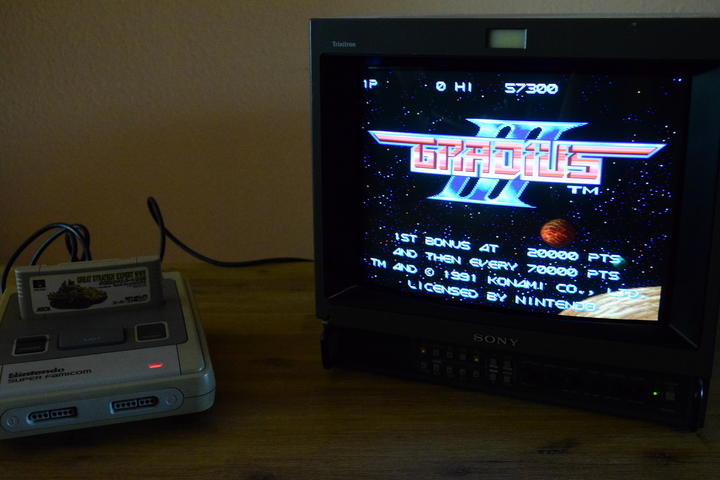
In any case, since May 2019, there's an ingenious patch penned by Vitor Vilela that provides a remedy in that regard. The patch offloads part of the calculations to the so-called SA-1 chip – a coprocessor that's installed ex factory in some game cartridges, including for example Super Mario RPG, Kirby's Dream Land 3 and Kirby Super Star. In this manner, the burden on the CPU is reduced and Gradius III runs buttery smooth!
Here is a video comparison.
And here's a more extensive one, done on genuine hardware.
I can also recommend this article which provides further information.
A ROM patched in this way can be played via emulation or by using a flashcart (provided these support the SA-1), and, if you build a respective physical cartridge yourself, even on genuine hardware. This is the path we want to take here.
At the time of writing, there are also patches in this vein for Contra III and Super Mario World. The hardware-oriented section of this tutorial is applicable analogously. Only Mario requires slightly different steps to generate the ROM file. Using Lunar Magic, you can furthermore create your own gameplay scenarios and patch them into the ROM. The technical constraints imposed on you are significantly lifted by the SA-1 patch. We won't go into that here, but if there's any questions, don't hesitate to ask.
This tutorial can be seen as a companion to Voultar's excellent, but slightly summarized video. I tried to address beginners first and foremost and explained a few steps more extensively, and/or compiled information from futher sources. I'm not liable to any harm you cause to your hardware or yourself; you're acting on your own responsibility
Section 0: Required parts and tools
We should have the following hardware in stock before beginning the build. The portion concerned with software can be done in advance, I'll go into that step by step:
• Gamebit 3.8mm screwdriver
• M27C322-compatible EPROM programmer
• Soldering equipment
• Heat gun
• Tweezers made of metal
• Pincer pliers
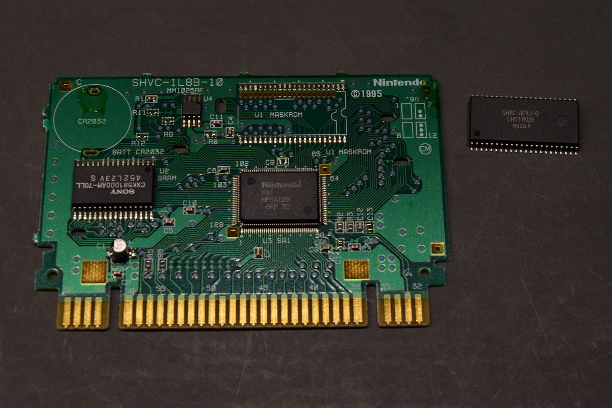
1x M27C322 EPROM
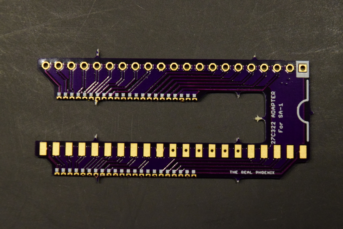
1x 27C322 SA-1 Adapter REV.3, courtesy of The Real Phoenix (⮞ obtainable via oshpark)
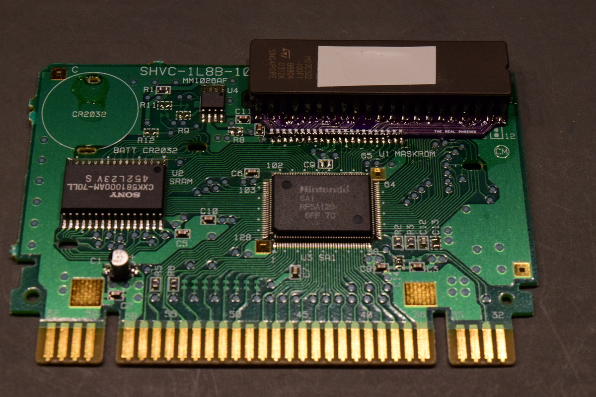
1x donor SNES cart with SA-1 Chip and 128KB SRAM: for this tutorial, the following games are qualified: Kakinoki Shogi (Label) or Daisenryaku Expert WWII - War in Europe (Label). More games can serve as a donor, see section "Variants" below.
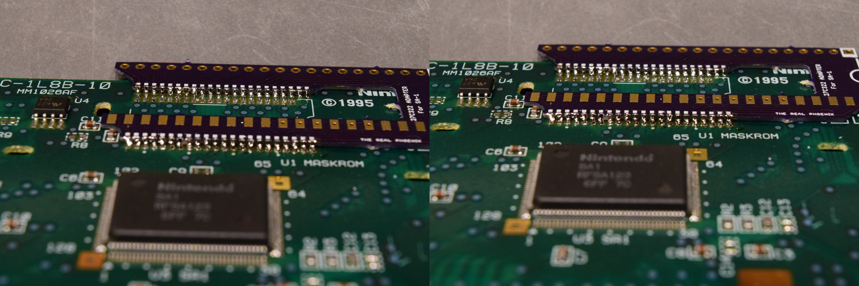
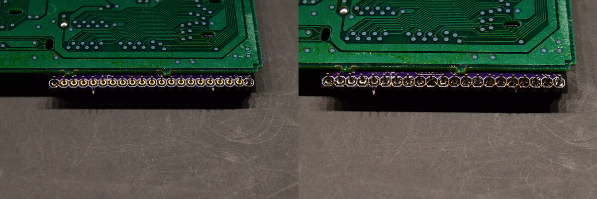
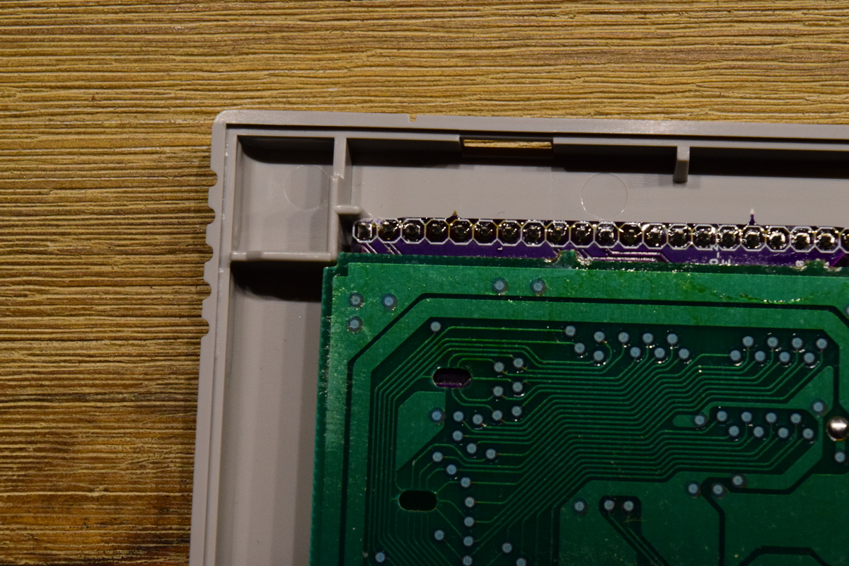
Note: Kakinoki Shogi uses a larger game PCB than Daisenryaku Expert, there is less space between it and the inner surface of the cartridge shell's top side. So using Kakinoki Shogi might necessitate further measures to make the finished game PCB/adapter board combination fit back into the cartridge shell. Or, it might not fit with The Real Phoenix's SA-1 Adapter REV.3 at all (if this is the case you might be limited to using FlashROM - see the 'Variants' section). Currently, I cannot give a final assessment, as I don't have a SHVC-1L8B-01 game PCB at hand, the PCB that Kakinoki Shogi uses. Maybe somebody can chime in on this and give more information on what is possible with that donor game and what isn't. In the meantime, you can use these PCB photos: [1] [2] and my photo below that shows how much space remains with Daisenryaku Expert, to gauge how this will pan out with Kakinoki Shogi.
Optional:
1x CR2032 battery holder (watch out: many don't fit! These apparently work.)
1x CR2032 battery
OR
no holder and 1x tabbed CR2032 battery instead (ones labelled 'Panasonic CR2032-HU3N' should work - 'HU3N' is the correct tab configuration.)
Section 1: Generation of patched ROM file and burning it onto the EPROM
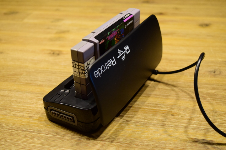
First we need an original Gradius III ROM file, in regards to where you get it from, you're on your own. I dumped my NTSC-U cartridge using a Retrode for this purpose:
Spoiler
To make sure you have a sound ROM dump, you should check its hash sum:
Spoiler
On Windows, bring up the command line tool (cmd.exe) and execute the following command:
On Linux, use the following command:
On OSX, use this:
If you have the NTSC-U version, the output should read , and for the NTSC-J version.
Code: Select all
certutil -hashfile pathToYourRomFile SHA1Code: Select all
sha1sum pathToYourRomFileCode: Select all
shasum pathToYourRomFileCode: Select all
7e62203a4198e9404eb7b076802c09786e5a63f4Code: Select all
e5119c731c9de5f942565ab0d752cb50abf4f32cWe then obtain the SA-1 patch by visiting Vitor Viela's GitHub repository, and downloading the latest Gradius III patch on the 'Releases' page.
Gradius-III-JPN.bps or Gradius-III-USA.bps – here you have to make sure to choose the file that matches your original ROM!
Using the BPS patcher of our choice, we apply the patch file to our original ROM file. I use FLIPS for this, beat is an alternative. We save the resulting file as 'G3-US_SA1.sfc'.
Our M27C322, which we want to burn using this file, has 4 MByte of memory, but G3-US_SA1.sfc only has a size of 512 kByte. We therefore inflate the patched game using the helper application Lunar Expand to match the size of our EPROM. We choose the option 32Mbit (4MB), and after clicking on "Apply to ROM..." we select our G3-US_SA1.sfc. Let the resulting file be called G3-US_SA1_padded.sfc in the further course, which should have a size of 4 MByte.
Contained in the header of every SNES ROM is a checksum, which is now incorrect due to our "inflation". Using uCON64, which is kind of a swiss army knife for video game ROM files, we can correct this. We download the executable appropriate for our operating system (for Linux I recommend to either build uCON64 from source, or to consult your distribution's package manager), open the command line, navigate to the directory where we put uCON64 and execute the following command:
Code: Select all
ucon64 pathToYour_G3-US_SA1_padded.sfcTo correct this, we now execute the following command:
Code: Select all
ucon64 --chk pathToYour_G3-US_SA1_padded.sfcCode: Select all
ucon64 pathToYour_G3-US_SA1_padded.sfcIf we now generate the hashsum again as described above, and if it reads as follows (assuming patch version 1.5), we can be sure to have done everything right up to this point:
Code: Select all
9aabdbdc8c5024c38899c2647cd871d83c572eff (NTSC-U version)
032e422fa66a16b4f27da9d12ed2bb7a7d24af10 (NTSC-J version)
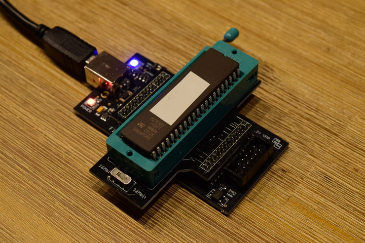
Preparation of our ROM file is complete now, and we can move on to burn it onto the 27C322. As for programming device, by way of example I'm using the FlashcatUSB XPORT in combination with a DIP-42 Adapter here:
Section 2: Preparation of the donor PCB
Upfront we should test our donor cartridge for correct function: in case something doesn't work later down the line, we will know whom to blame and isolation of the error will be easier
Green light? Then we free the donor PCB from its case using the Gamebit and carefully put the halves aside. The markings on the PCB tell us about the functions of all relevant components. On this occasion it's a good idea to give the contacts of the edge connector a good clean using isopropyl alcohol and cotton swabs, since they're well accessible now.
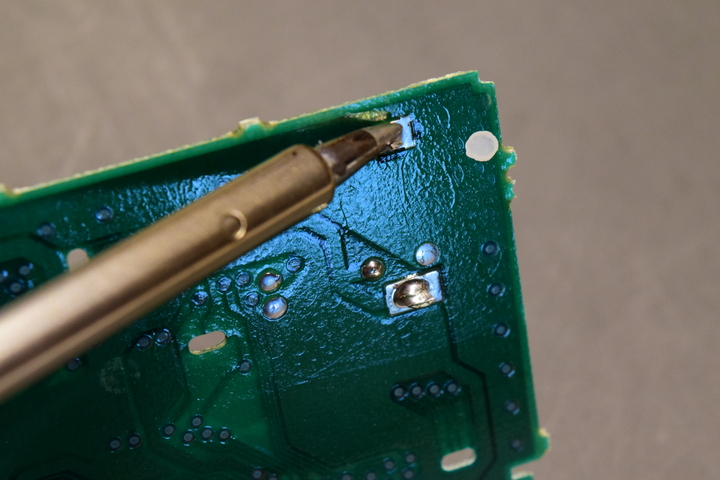
At first we desolder the old battery:
Spoiler
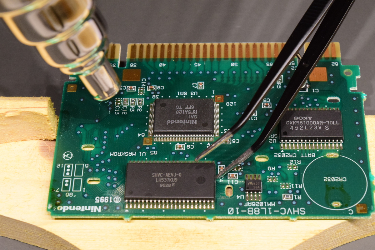
In the next step we remove the MaskROM. Due to its type we cannot easily get at it with the soldering iron. A workable method consists in using a hot air gun. It doesn't have to be a particularly high-end device; for this tutorial I use a run-of-the-mill model that was on offer for cheap in a supermarket. Along with it a narrower reduction nozzle which is subsequently used:
Spoiler

The MaskROM detached, we let it and the PCB cool down for a bit. Afterwards we remove any solder spilled onto the PCB in the process. We don't have to clean the old solder off of the pads; instead we can reuse it later by refreshing it with new solder, easing the soldering of the adapter board a little.
Section 3: Soldering the adapter board and EPROM
After breaking the adapter board out of the panel, small protrusions remain due to the perforation, which should be clipped or sanded off (this is especially important for those residing in-between the edge pins, otherwise it will be hard to get good solder flow later):
Spoiler
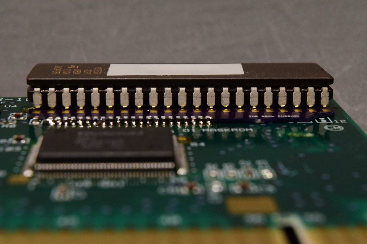
We align the adapter board to the exposed pads as evenly as possible, like the following photo shows (marking "The Real Phoenix" has to point to the game's edge connector):
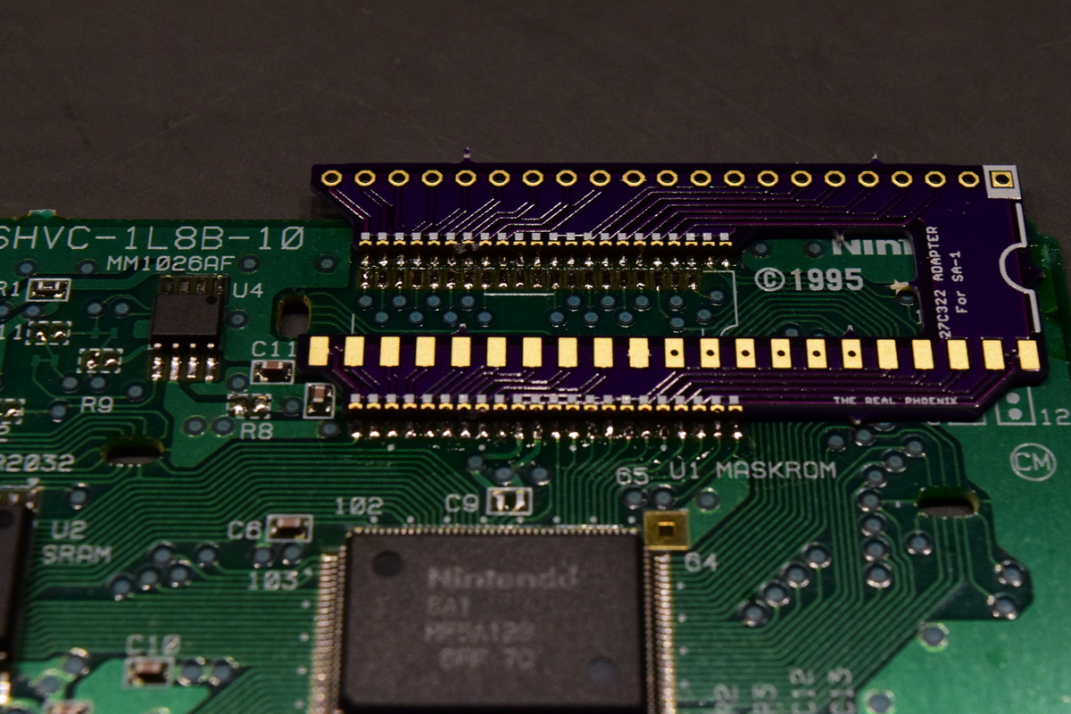
(Sorry, the edges turned out a little dark...)
We want to avoid attaching the board too far up, the spacing between it and the plastic shell is quite tight unfortunately, else we might later need to file down one corner of the PCB a little, before it will be possible to screw down the cart again. We dab the resulting junctions in flux and slowly move the soldering iron along the edge. Because of the flux, the solder should find the way by itself, if necessary we apply a little bit of additional solder, but not too much, otherwise bridges can form. To initially lock the board in place, it can help to - like Voultar does it - only solder a few contacts at one corner at first, followed by the diagonally opposite corner.
Once all contacts are soldered, we carefully inspect the contacts for bridges, ideally both visually and by using a multimeter, the counterpart being the respective via or pad for the EPROM on the adapter board. It's by design that the adapter board doesn't connect pin 32 of the M27C322.
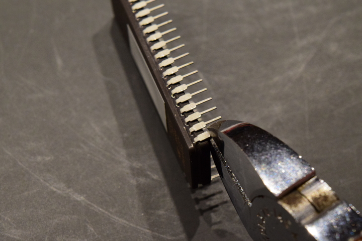
Now, only the EPROM remains: one pin row goes through the vias, the other one rests on the pads. For the latter, we have to trim the pigtails, meaning the narrower parts, which we do using a pair of pliers. If we observe the correct orientation (the notch on the EPROM is correspondingly marked on the adapter board), we know which side has to be trimmed. The trimmed pin row should rest on the pads as evenly as possible, so we trim protruding pins again until all pins have approximately the same length. Finally we solder both pin rows onto the adapter board:
Spoiler
Spoiler
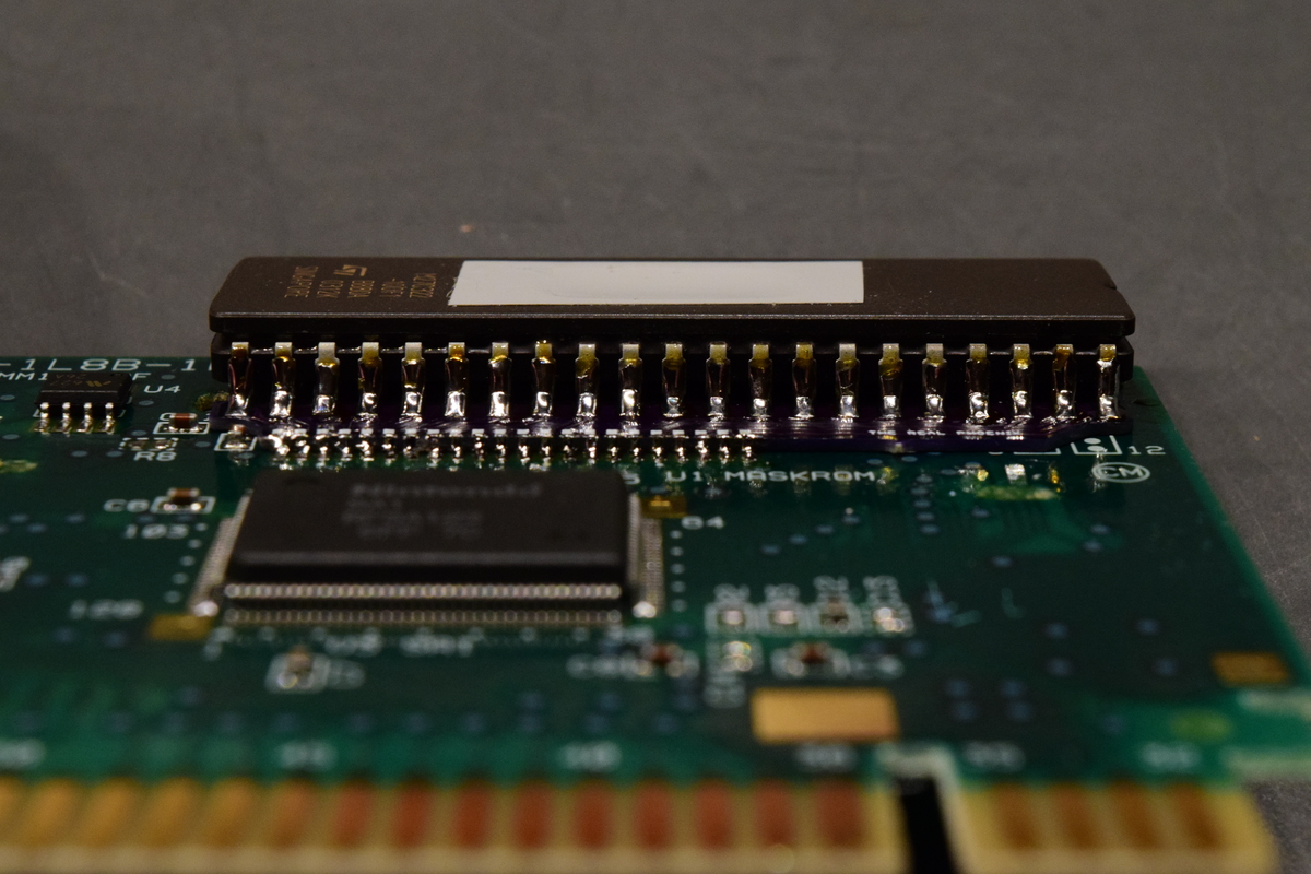
Done! Time to give the cartridge a try.
As for the label... I'll have to come up with something ^^'
Variants
Further possible donor cartridges
In principle, all SNES/SFC games that have an SA-1 chip at their disposal can serve as a donor. (Wikipedia provides further information, sort by column "Chip" there).
With games other than those two mentioned at the beginning, you have to upgrade the SRAM. You need the following part for this: IS62C1024AL-35QLI-TR. It appears that in most cases, the new SRAM chip cannot be soldered in directly; the exact procedure depends on the game PCB revision at hand. 1L5B or 1L3B-10/11 e.g. (PGA European Tour Golf, PAL) do have the necessary additional solder pads, but they're located below the solder resist mask and have to be revealed beforehand:
Spoiler

Spoiler

M27C160 instead of M27C322
In compliance with one additional facet, it's possible to use a M27C160 in place of a M27C322. As opposed to the former, the latter not only has a 16bit-, but an additional 8bit mode. We need 16bit – which we tell the M27C160 by soldering it normally, except for pin 32, which we let float at first. We then connect it with a 5V source (pin 22 on the M27C160 is suitable). In Lunar Expand we divergently choose "16Mbit (2MB)", all checksums change accordingly.
FlashROM instead of EPROM
Instead of an EPROM in combination with an adapter board, a FlashROM can also be used, for example the 29F1610 (pin 1 has to be set to 5V) or the 29L3211 (Careful: operating voltage is 3.3V for the latter, so you need a voltage regulator). One implementation of this can be seen e.g. here. Note: the 29F1610 is erroneously listed as "28F1610" there. Factor in the correct ROM size in Lunar Expand, all checksums change accordingly.
Changelog:
Spoiler
Oct 07, 2020:
- Added a better comparison video.
- Mentioned using a tabbed coin cell battery as an alternative to using a battery holder.
- Added a note and accompanying photo about filing down one corner of the adapter PCB a little in case the game and adapter PCB combination doesn't otherwise properly fit into the cartridge shell.
- Added a note about potential limitations/necessary extra steps due to the larger PCB of donor candidate 'Kakinoki Shougi'.


![[1]](https://datomatic.no-intro.org/sources%20media/Nintendo%20-%20Super%20Nintendo%20Entertainment%20System/20190619_190956_1300_pcb_back.jpg)
![[2]](https://datomatic.no-intro.org/sources%20media/Nintendo%20-%20Super%20Nintendo%20Entertainment%20System/20190618_204221_0524_pcb_back.jpg)