I would like to mod a Japanese model1 Megadrive VA4 by doing the least amount of changes to the system (and none to the shell).
Ie, I would like to re-use the Din8 output and also keep the front headphone jack in working order (even if signal to noise ratio is pretty bad on this one).
For Audio I found an official mod by Akinori Nishiyama (WORKS NISHI), that can be seen here:
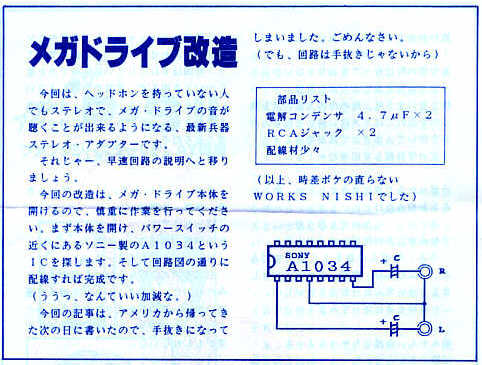
On this page, a user does this mod by replacing:

- the "+5V" on Pin4 of the Din8 by the "Left audio" channel.
- the "Mono sound" on Pin1 of the Din8 by "Right audio" channel
Now my question is the following: I see many solutions for MD audio called "Mega Amp", a project by FirebrandX, etc..
Is this "official" method by WORKS NISHI flawed in any way? If not, why isn't it the prefered method for restoring Stereo on model 1s?
I'm mainly concerned about the sound volume level after doing this mod. If it's on par with the original Mono volume level on the Din8 it'll be fine enough for me.
----------------------------------------------------------------------------------------------------------------------------------
For Video of course my goal is clean RGB, for it to work on both my BVM and XRGB Mini, hopefully without jailbars.
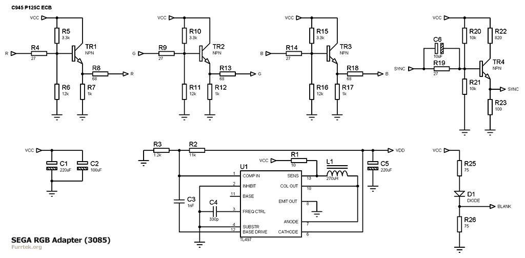
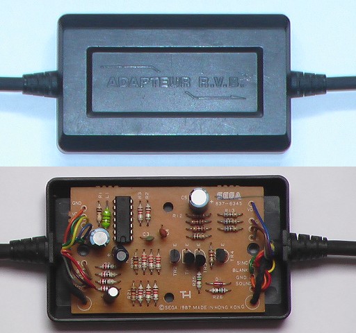
First I got an official Euro Sega RGB cable (R.V.B adaptor model 3085) and applied the mod from this french page to make it compatible with my JPN MD (which in a nutshell involves replacing the SYNC signal by the CVBS signal on input).
Then I realised it was completely silly because I DO want to use CSYNC rather than CVBS, since it apparently removes (most of) the jailbars.
And so I stumbled upon a mystery: Pin7 of the Din8 is supposed to carry SYNC on Japanese MDs but apparently Sega screwed up and connected Pin7 to "CSync in" (pin10 of the CXA1145) instead of "Csync out" (pin11 of the CXA1145).
And by checking my VA4 it certainly seems true, pin11 seems connected to nothing..
However it seems that this isn't a real issue?
Would anyone know if on JPN VA4 the SYNC signal coming out from Din8 is usable at all?
As is, meaning with "Sync in" wired instead of "Sync out" on Din8 Pin7 because of Sega's mistake, does the Sync line also need a 220uF cap + 75ohm resistor to work properly?
Apparently also the Model 3085 mod from that french page isn't even necessary, as another user proposes to keep using the SYNC signal on input but to remove resitor R19 for proper SYNC on NTSC systems.
If so, I would just restore the SYNC trace that I cut on my modded Model 3085, remove the R19 resistor (and possibly add a 220uF cap + 75ohm resistor instead) and call it a day?
Thanks for any input, thoughts, etc.. ^^