Found a Sony KV-XF21M30 in the street today. It works fine so I thought I'd try and do a OSD RGB Mod with it. I'm currently only in the research phase so I thought I'd post what I've come up with and my mod proposal and see if I can get some advice from the OSD RGB modders on this forum.
I was unable to find the exact service manual for this TV but examination of the chassis PCB and some judicious googling I found that this service manual https://drive.google.com/file/d/0BxXDEF ... sp=sharing for the KV-XG29M30 had an exact matching chassis.
Edit: Ended up finding a HTML version of the correct service manual https://servicemanuals.us/sony/tv/kv-xf ... l?start=36 and this PDF for the KV-XF21M31 which appears identical but for the New Zealand market. https://drive.google.com/open?id=0BxXDE ... WhTM0I1bFk
I then grabbed the datasheets for the:
OSD Chip CXP86441 https://drive.google.com/file/d/0BxXDEF ... sp=sharing
Teletext Chip https://drive.google.com/open?id=0BxXDE ... mw1MC1hdFE
Sound Chip https://drive.google.com/open?id=0BxXDE ... HBtZFNaQWs (well, why not while I'm at it?)
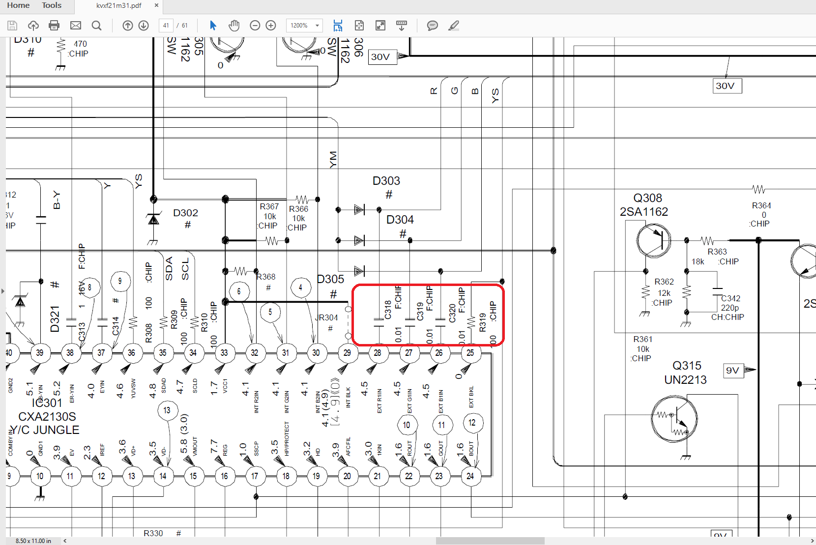
In the block diagram for the chassis you can see that the Jungle Chip can take RGB from either the OSD or the Teletext stream. (NB:my set doesn't have Teletext option)
https://drive.google.com/open?id=0BxXDE ... 3VrY19QcE0
Furthermore, the Teletext RGB/Blanking feed comes through a connector, CN307
https://drive.google.com/open?id=0BxXDE ... W9wX0Rmb0U
On my TV, this "CN307" connector is not populated and easy to locate.
https://drive.google.com/open?id=0BxXDE ... WFXVnZGZGs
So, this brings me to my proposed mod.
1) Populate the CN307, either with the proper header/plug or soldering wires/pins into place.
2) Connect the Scart RGB and 5V lines to the CN307 connector, possibly with a potentiometer on the 5v line
3) Terminate the RGB lines to ground via a 75ohm resistor.
Would really love some advice here. Have never attempted this before.
I do have some questions
1) I can't seem to narrow down the exact voltage required on the RGB lines.
2) do I "75ohm terminate" to the Scart ground or the TV's ground? (or does it matter?)
3) Does anyone know a standard plug that will fit the CN307? (I'm sure this is minor but if there is a cheap, standard header/plug would look pro)
All help appreciated.
MarkOZLAD
RGB OSD TV Mod - Sony KV-XF21M30
-
MarkOZLAD
- Posts: 1040
- Joined: Thu May 18, 2017 12:39 pm
RGB OSD TV Mod - Sony KV-XF21M30
___________________________________________________
MarkOZLAD
OSD/External RGB Mux Diagram
OSD/External RGB Mux Resistor Value Table 0.7Vp-p : 0.5Vp-p
"Imagine toggle switch OSD modding a TV in 2019" - maxtherabbit
MarkOZLAD
OSD/External RGB Mux Diagram
OSD/External RGB Mux Resistor Value Table 0.7Vp-p : 0.5Vp-p
"Imagine toggle switch OSD modding a TV in 2019" - maxtherabbit
-
MarkOZLAD
- Posts: 1040
- Joined: Thu May 18, 2017 12:39 pm
Re: RGB OSD TV Mod - Sony KV-XF21M30
I'm still unable to find the datasheet for the SONY CXA2130S Jungle Chip that is in this TV. I did, however, find a few other datasheets for SONY Jungle I/C's and they all had 0.7V p-p specified for the RGB lines. So I will assume that is the case for this chip too.
I note that the Blanking signals seem to specify 0.7V (or a range of 0.4V-1.0V). As mentioned in earlier post I will put a potentiometer on my 5V line, start with it off and slowly turn it up.
I note that the Blanking signals seem to specify 0.7V (or a range of 0.4V-1.0V). As mentioned in earlier post I will put a potentiometer on my 5V line, start with it off and slowly turn it up.
___________________________________________________
MarkOZLAD
OSD/External RGB Mux Diagram
OSD/External RGB Mux Resistor Value Table 0.7Vp-p : 0.5Vp-p
"Imagine toggle switch OSD modding a TV in 2019" - maxtherabbit
MarkOZLAD
OSD/External RGB Mux Diagram
OSD/External RGB Mux Resistor Value Table 0.7Vp-p : 0.5Vp-p
"Imagine toggle switch OSD modding a TV in 2019" - maxtherabbit
-
MarkOZLAD
- Posts: 1040
- Joined: Thu May 18, 2017 12:39 pm
Re: RGB OSD TV Mod - Sony KV-XF21M30
So, in short my mod worked....
After I was informed about how to correctly to do the 75Oohm termination to ground ( see TV RGB Mod thread) I created my circuits. I had a Scart to component /stereo RCA cable lying around, it is designed for Foxtel YUV connections. - Y/U/V/L audio/R Audio. The YUV connections were the same pins as RGB so I opened up the scart end of the cable and desoldered the R Audio cable and attached it to the Scart plugs Component Sync Signal and Ground pins to give me a R/G/B/Sync/Left Audio RCA breakout cable. I then purchased inexpensive female RCA jacks and soldered signal and ground wires to them and connected the signal to ground via a 75Ohm resistor. My work wasn't pretty but good enough for prototype. I also wired up a potentiometer to a ground wire, what I thought was 5V on the TV chassis, and an output jumper lead.
The aforementioned teletext board connector, the target for my RGB signals on the chassis, had solder in place underneath it. It needed to be removed. I was then able to put the pin ends of jumper cables into the Red, Green, Blue, Blk and Ground holes and solder from the underside.
For my blanking signal I connected a wire to the output of the 5V Regulator IC on the chassis (this lead to near disaster but we can talk about that later...)
So i attached my wires and had the potentiometer set to maximum attenuation....It immediately got hot and I disconnected it. Smelled a bit! I later connected what my "5V" line directly to the blanking line and things got really hot. Rookie mistake! Luckily this is my throwaway, practice TV!
Turns out that sending a voltage to the blanking was unnecessary. All this set needed was the RGB signal to be sent to the Jungle IC, the Sync to be connected to an AV input port and the correct AV input to be selected. Voila RGB mode! (I now see on the thread that others have found Sony Trinitrons that don't require blanking signal).
Note, this TV worked equally well with Composite video as it did with Composite Sync.
Unfortunately this TV has a horizontal convergence issue. The first time I ever turned the TV on it showed up but after I cycled the power it went away. It has now come back with a vengeance.
https://drive.google.com/file/d/0BxXDEF ... sp=sharing
https://drive.google.com/file/d/0BxXDEF ... sp=sharing
https://drive.google.com/file/d/0BxXDEF ... sp=sharing
The convergence issue is intermittent and I have seen it in RGB mode without the convergence issue and I'll have to say the picture quality is quite amazing on this set. RGB modding is very worthwhile and Sony Trinitrons appear one of the best sets to do it on, especially if there is a Teletext connector to attach to, makes life easy.
___________________________________________________
MarkOZLAD
OSD/External RGB Mux Diagram
OSD/External RGB Mux Resistor Value Table 0.7Vp-p : 0.5Vp-p
"Imagine toggle switch OSD modding a TV in 2019" - maxtherabbit
MarkOZLAD
OSD/External RGB Mux Diagram
OSD/External RGB Mux Resistor Value Table 0.7Vp-p : 0.5Vp-p
"Imagine toggle switch OSD modding a TV in 2019" - maxtherabbit
-
MarkOZLAD
- Posts: 1040
- Joined: Thu May 18, 2017 12:39 pm
Re: RGB OSD TV Mod - Sony KV-XF21M30
Last night I revisited this TV. After my experience with the LG TV I was working on I realised that I couldn't be sure that my RGB Mod had worked because my DVD player is outputting composite video via SCART. Thus what I was seeing may have been composite video via scart instead of RGB. Also, whilst I was away overseas recently I whiled away the hours on my plane rides studying TV chassis diagrams. Fun eh? I realised that I may have hooked up my blanking line to the 9V input of the 5V regulator on the TV chassis instead of the 5V output.
Once I opened up the set I found that I had indeed hooked up the blanking line to the incorrect pin. A quick snip and re-solder to the 5V output was done.
After this, SUCCESS! Hooking up the now 5V blanking signal caused the TV to go into RGB mode. I was able to prove it was running RGB by unplugging each colour signal.
If you're looking for a Sony Trinitron to RGB mod I would recommend one with the BG-3S chassis. By just feeding the RGB signals through the Teletext port, Composite video through the AV port and hooking up the blanking signal to the output of the 5V regulator this will be one of the easier and more elegant solutions possible.
Now if only I could fix my convergence issues...One thing at a time!
___________________________________________________
MarkOZLAD
OSD/External RGB Mux Diagram
OSD/External RGB Mux Resistor Value Table 0.7Vp-p : 0.5Vp-p
"Imagine toggle switch OSD modding a TV in 2019" - maxtherabbit
MarkOZLAD
OSD/External RGB Mux Diagram
OSD/External RGB Mux Resistor Value Table 0.7Vp-p : 0.5Vp-p
"Imagine toggle switch OSD modding a TV in 2019" - maxtherabbit
-
konp
- Posts: 8
- Joined: Wed Nov 01, 2017 11:05 am
Re: RGB OSD TV Mod - Sony KV-XF21M30
Hey man, I happen to have the exact same model set sitting in my back room (only it had the teletext module, so I removed it).
Any way you could post detailed pics of the circuit/wiring you used so I can replicate it on mine?
I just tried, and it's definitely receiving SOMEthing, but all I get is a blue screen with faint wiggly lines on it. Blue like it's not receiving anything.
If it makes any difference, my video sending device is a raspberry pi 3 with a gert vga666 adapter. I've tried a sync circuit based on a 74HC86 but it doesn't seem to have worked.
-
MarkOZLAD
- Posts: 1040
- Joined: Thu May 18, 2017 12:39 pm
Re: RGB OSD TV Mod - Sony KV-XF21M30
Solder a 0.1" (2.54) header into the empty Teletext port. CN307.konp wrote:Hey man, I happen to have the exact same model set sitting in my back room (only it had the teletext module, so I removed it).
Any way you could post detailed pics of the circuit/wiring you used so I can replicate it on mine?
I just tried, and it's definitely receiving SOMEthing, but all I get is a blue screen with faint wiggly lines on it. Blue like it's not receiving anything.
If it makes any difference, my video sending device is a raspberry pi 3 with a gert vga666 adapter. I've tried a sync circuit based on a 74HC86 but it doesn't seem to have worked.
Connect a ground wire to the Teletext ground
Connect your external RGB lines to ground via 75Ohm resistors and then have them run to the Teletext RGB ports.
Connect a line from the output of the 5V regulator (IC604) into the blanking pin (BLK) of the teletext port. I normally use a switch so I can turn off the RGB. Another option here would be to run the Scart Pin 16's blanking signal to this pin.
Take sync and sync ground into an AV port and change the input of the set to that input. I usually use an RCA AV cable of some sort.
In order to get the OSD to be less washed out you might want to experiment with adding resistors to the external RGB lines.
___________________________________________________
MarkOZLAD
OSD/External RGB Mux Diagram
OSD/External RGB Mux Resistor Value Table 0.7Vp-p : 0.5Vp-p
"Imagine toggle switch OSD modding a TV in 2019" - maxtherabbit
MarkOZLAD
OSD/External RGB Mux Diagram
OSD/External RGB Mux Resistor Value Table 0.7Vp-p : 0.5Vp-p
"Imagine toggle switch OSD modding a TV in 2019" - maxtherabbit
-
konp
- Posts: 8
- Joined: Wed Nov 01, 2017 11:05 am
Re: RGB OSD TV Mod - Sony KV-XF21M30
Ah, very good.MarkOZLAD wrote:Solder a 0.1" (2.54) header into the empty Teletext port. CN307.konp wrote:Hey man, I happen to have the exact same model set sitting in my back room (only it had the teletext module, so I removed it).
Any way you could post detailed pics of the circuit/wiring you used so I can replicate it on mine?
I just tried, and it's definitely receiving SOMEthing, but all I get is a blue screen with faint wiggly lines on it. Blue like it's not receiving anything.
If it makes any difference, my video sending device is a raspberry pi 3 with a gert vga666 adapter. I've tried a sync circuit based on a 74HC86 but it doesn't seem to have worked.
Connect a ground wire to the Teletext ground
Connect your external RGB lines to ground via 75Ohm resistors and then have them run to the Teletext RGB ports.
Connect a line from the output of the 5V regulator (IC604) into the blanking pin (BLK) of the teletext port. I normally use a switch so I can turn off the RGB. Another option here would be to run the Scart Pin 16's blanking signal to this pin.
Take sync and sync ground into an AV port and change the input of the set to that input. I usually use an RCA AV cable of some sort.
In order to get the OSD to be less washed out you might want to experiment with adding resistors to the external RGB lines.
I actually have the header on the board already - for some reason my model had the teletext module installed, even though I'm in Australia. I just took the card out - the board headers are female so I can just push pins into the sockets.
What do you reckon the best way of creating csync from the v and h sync coming from the VGA port would be? Note by "best" I mean "works, is decent quality, and doesn't require an insanely complex circuit to achieve".
Also the ground to the teletext GND - is that required? Or is that only for the RGB 75 ohm termination - if so, doing that "externally" i.e. on a breakout board, should still work as ground there will be the same voltage potential (0V relative to VCC and blanking, which should be 5v, correct?)
-
MarkOZLAD
- Posts: 1040
- Joined: Thu May 18, 2017 12:39 pm
Re: RGB OSD TV Mod - Sony KV-XF21M30
You could've left the teletext board in place and soldered to the underside pins. If you did that you could've tested blanking by pressing the teletext buttonkonp wrote: Ah, very good.
I actually have the header on the board already - for some reason my model had the teletext module installed, even though I'm in Australia. I just took the card out - the board headers are female so I can just push pins into the sockets.
A friend of mine has used the method where you put 1kohm resistors on each of the h and v sync lines and then twisting them together. He is happy with it.konp wrote: What do you reckon the best way of creating csync from the v and h sync coming from the VGA port would be? Note by "best" I mean "works, is decent quality, and doesn't require an insanely complex circuit to achieve".
I just use the Teletext ground because it's easy. Any ground should be fine.konp wrote:Also the ground to the teletext GND - is that required? Or is that only for the RGB 75 ohm termination - if so, doing that "externally" i.e. on a breakout board, should still work as ground there will be the same voltage potential (0V relative to VCC and blanking, which should be 5v, correct?)
___________________________________________________
MarkOZLAD
OSD/External RGB Mux Diagram
OSD/External RGB Mux Resistor Value Table 0.7Vp-p : 0.5Vp-p
"Imagine toggle switch OSD modding a TV in 2019" - maxtherabbit
MarkOZLAD
OSD/External RGB Mux Diagram
OSD/External RGB Mux Resistor Value Table 0.7Vp-p : 0.5Vp-p
"Imagine toggle switch OSD modding a TV in 2019" - maxtherabbit
-
konp
- Posts: 8
- Joined: Wed Nov 01, 2017 11:05 am
Re: RGB OSD TV Mod - Sony KV-XF21M30
I could have, yeah, but last time I tried soldering to a Sony chassis board that old, the pads ripped off the board with basically no prompting. Even with decent soldering skills and a temperature-controlled iron. I figured avoiding that scenario again was preferable - and if the input still works without the board being present, then all the better for it.MarkOZLAD wrote:You could've left the teletext board in place and soldered to the underside pins. If you did that you could've tested blanking by pressing the teletext buttonkonp wrote: Ah, very good.
I actually have the header on the board already - for some reason my model had the teletext module installed, even though I'm in Australia. I just took the card out - the board headers are female so I can just push pins into the sockets.
A friend of mine has used the method where you put 1kohm resistors on each of the h and v sync lines and then twisting them together. He is happy with it.konp wrote: What do you reckon the best way of creating csync from the v and h sync coming from the VGA port would be? Note by "best" I mean "works, is decent quality, and doesn't require an insanely complex circuit to achieve".
I just use the Teletext ground because it's easy. Any ground should be fine.konp wrote:Also the ground to the teletext GND - is that required? Or is that only for the RGB 75 ohm termination - if so, doing that "externally" i.e. on a breakout board, should still work as ground there will be the same voltage potential (0V relative to VCC and blanking, which should be 5v, correct?)
I've tried the 1-k resistor-twist method before and it mostly worked, but I got horizontal distortion right at the top of the screen - about an inch of the image was skewed off to one side. I've found a circuit using a BC548 or equivalent transistor and four resistors; I might try that and see what happens.
Good to know about the ground, thanks. I figured that was the case, as it usually is, but CRT TVs like to defy expectations at the best of times.
-
MarkOZLAD
- Posts: 1040
- Joined: Thu May 18, 2017 12:39 pm
Re: RGB OSD TV Mod - Sony KV-XF21M30
Interested to know the details of this circuit.konp wrote:I've found a circuit using a BC548 or equivalent transistor and four resistors; I might try that and see what happens.
___________________________________________________
MarkOZLAD
OSD/External RGB Mux Diagram
OSD/External RGB Mux Resistor Value Table 0.7Vp-p : 0.5Vp-p
"Imagine toggle switch OSD modding a TV in 2019" - maxtherabbit
MarkOZLAD
OSD/External RGB Mux Diagram
OSD/External RGB Mux Resistor Value Table 0.7Vp-p : 0.5Vp-p
"Imagine toggle switch OSD modding a TV in 2019" - maxtherabbit
-
konp
- Posts: 8
- Joined: Wed Nov 01, 2017 11:05 am
Re: RGB OSD TV Mod - Sony KV-XF21M30
It be this one right here:MarkOZLAD wrote:Interested to know the details of this circuit.konp wrote:I've found a circuit using a BC548 or equivalent transistor and four resistors; I might try that and see what happens.
http://www.nexusuk.org/projects/vga2scart/circuit
-
konp
- Posts: 8
- Joined: Wed Nov 01, 2017 11:05 am
Re: RGB OSD TV Mod - Sony KV-XF21M30
So that circuit was effing useless. Barely synced, gave me a constantly vertically-rolling signal.
So I tried the 1k resistor twist trick - it sort of worked. As long as I was holding the output of the resistors (my guess is the capacitance of my body smoothed the signal somewhat). Still wasn't great, but I was at least able to see a picture and confirm that RGB was being had.
Back to the drawing board for sync circuits I guess.
On a slightly different topic - I had slowly-scrolling bars of faint visual noise as well, and I couldn't figure out where they were coming from. Do you have any ideas? Sorry if I'm annoying you, it's just that you've done this exact mod on this exact TV model before, so you're basically the authority on the subject
-
konp
- Posts: 8
- Joined: Wed Nov 01, 2017 11:05 am
Re: RGB OSD TV Mod - Sony KV-XF21M30
Ah screw it I just bought a UMSA. I'll see what happens once it arrives.
-
MarkOZLAD
- Posts: 1040
- Joined: Thu May 18, 2017 12:39 pm
Re: RGB OSD TV Mod - Sony KV-XF21M30
konp wrote:So that circuit was effing useless. Barely synced, gave me a constantly vertically-rolling signal.
So I tried the 1k resistor twist trick - it sort of worked. As long as I was holding the output of the resistors (my guess is the capacitance of my body smoothed the signal somewhat). Still wasn't great, but I was at least able to see a picture and confirm that RGB was being had.
Back to the drawing board for sync circuits I guess.
On a slightly different topic - I had slowly-scrolling bars of faint visual noise as well, and I couldn't figure out where they were coming from. Do you have any ideas? Sorry if I'm annoying you, it's just that you've done this exact mod on this exact TV model before, so you're basically the authority on the subject
Have you connected the sync ground?
Might be an idea to post some photos.
___________________________________________________
MarkOZLAD
OSD/External RGB Mux Diagram
OSD/External RGB Mux Resistor Value Table 0.7Vp-p : 0.5Vp-p
"Imagine toggle switch OSD modding a TV in 2019" - maxtherabbit
MarkOZLAD
OSD/External RGB Mux Diagram
OSD/External RGB Mux Resistor Value Table 0.7Vp-p : 0.5Vp-p
"Imagine toggle switch OSD modding a TV in 2019" - maxtherabbit
-
konp
- Posts: 8
- Joined: Wed Nov 01, 2017 11:05 am
Re: RGB OSD TV Mod - Sony KV-XF21M30
I have, yes. I used a composite video cable I had - attached the shield/ring to ground, center pin to Csync. Plugged that into the Y input on the back.MarkOZLAD wrote:konp wrote:So that circuit was effing useless. Barely synced, gave me a constantly vertically-rolling signal.
So I tried the 1k resistor twist trick - it sort of worked. As long as I was holding the output of the resistors (my guess is the capacitance of my body smoothed the signal somewhat). Still wasn't great, but I was at least able to see a picture and confirm that RGB was being had.
Back to the drawing board for sync circuits I guess.
On a slightly different topic - I had slowly-scrolling bars of faint visual noise as well, and I couldn't figure out where they were coming from. Do you have any ideas? Sorry if I'm annoying you, it's just that you've done this exact mod on this exact TV model before, so you're basically the authority on the subject
Have you connected the sync ground?
Might be an idea to post some photos.
As it stands I've proved it works as I've gotten a mostly stable (with some issues) image, showing that at least the input functions as expected. As for the rest of it, until the UMSA arrives, my guess is just signal noise from lack of shielding/crappy soldering.
-
konp
- Posts: 8
- Joined: Wed Nov 01, 2017 11:05 am
Re: RGB OSD TV Mod - Sony KV-XF21M30
Just a thought, should my RGB lines have 0.1uf clamping caps in series in addition to the 75 ohm terminations to ground?
-
MarkOZLAD
- Posts: 1040
- Joined: Thu May 18, 2017 12:39 pm
Re: RGB OSD TV Mod - Sony KV-XF21M30
I didn't add any caps. Caps are already in place on the board.
___________________________________________________
MarkOZLAD
OSD/External RGB Mux Diagram
OSD/External RGB Mux Resistor Value Table 0.7Vp-p : 0.5Vp-p
"Imagine toggle switch OSD modding a TV in 2019" - maxtherabbit
MarkOZLAD
OSD/External RGB Mux Diagram
OSD/External RGB Mux Resistor Value Table 0.7Vp-p : 0.5Vp-p
"Imagine toggle switch OSD modding a TV in 2019" - maxtherabbit