CPS2 digital AV interface

Re: CPS2 digital AV interface
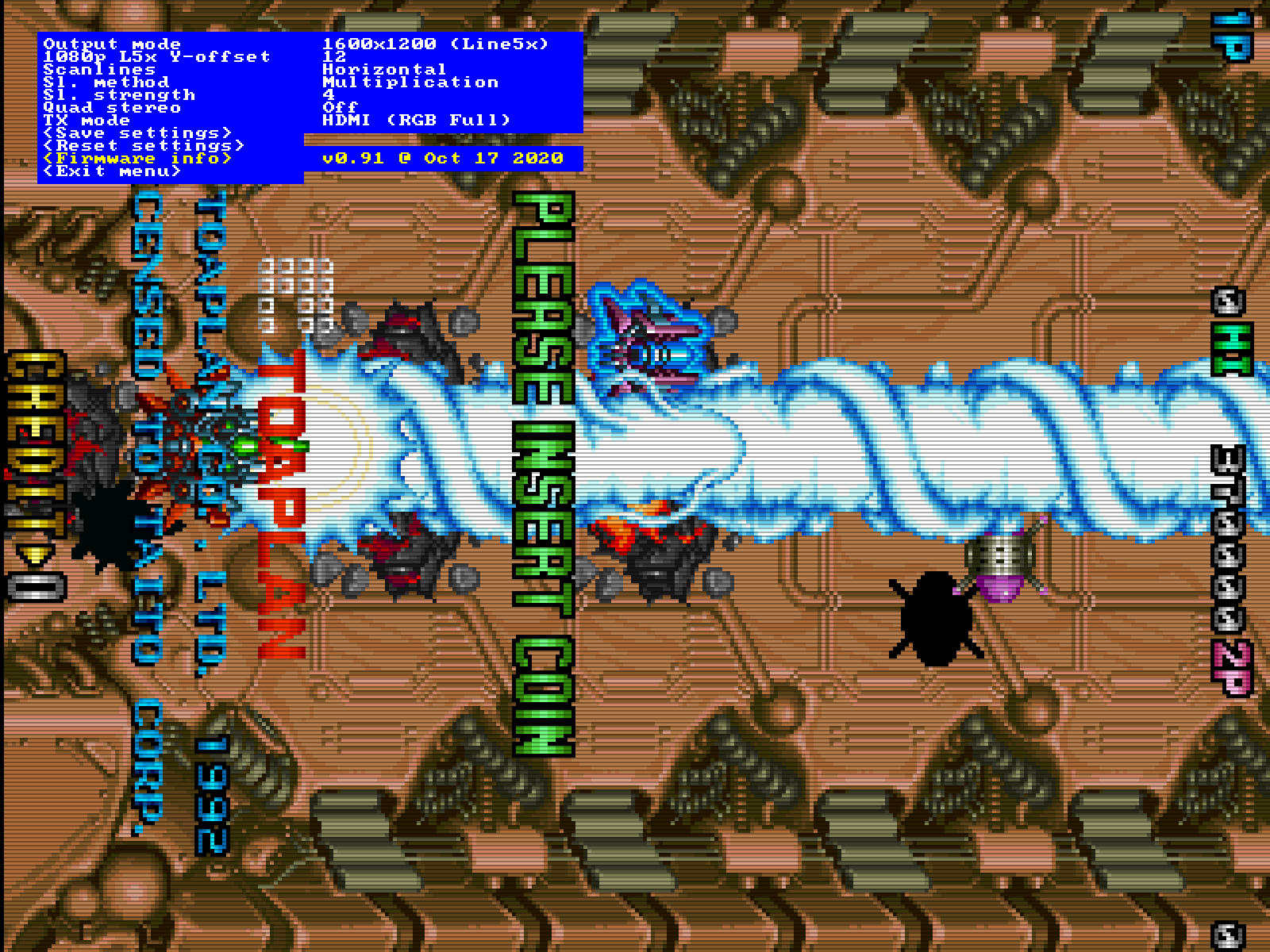
Scanline support has been added and firmware images (v0.91) have been generated for all supported systems (cps1-3, toaplan2). The project is more or less complete now. I might be still looking into adding support for Taito F3 some time in future.
-
thchardcore
- Posts: 484
- Joined: Wed Jun 22, 2005 9:20 am
- Location: Liberal cesspool
Re: CPS2 digital AV interface
Thank you for all the hard work.
A camel is a horse designed by a committee
Re: CPS2 digital AV interface
Updated today my CPS2, thanks for making it so great !
I was afraid of having only 2 buttons to be a bit tedious but it works well
I was afraid of having only 2 buttons to be a bit tedious but it works well
-
thchardcore
- Posts: 484
- Joined: Wed Jun 22, 2005 9:20 am
- Location: Liberal cesspool
Re: CPS2 digital AV interface
Any idea when these will come back in stock? Not sure why I waited so long.
A camel is a horse designed by a committee

Re: CPS2 digital AV interface
Thanks a lot. It works like a charm.
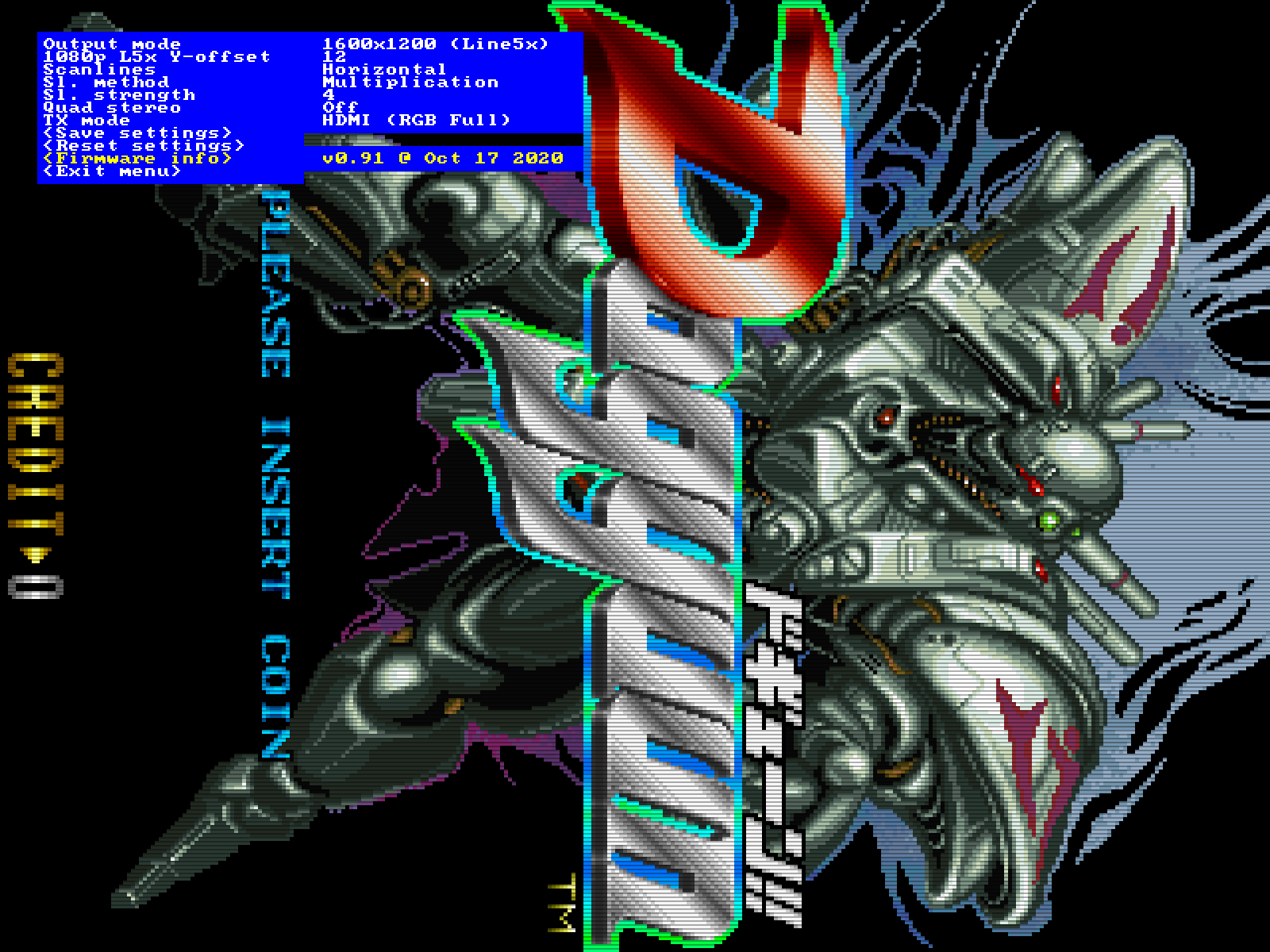
A few screenshots (click for full size, the scanline effect doesn't look right otherwise):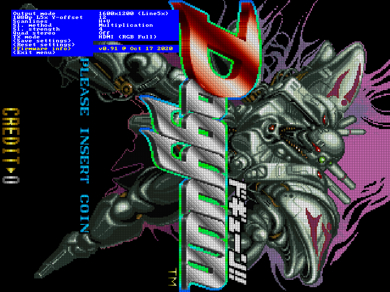
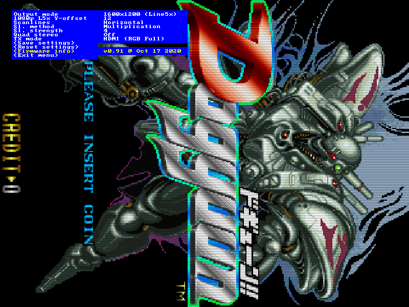
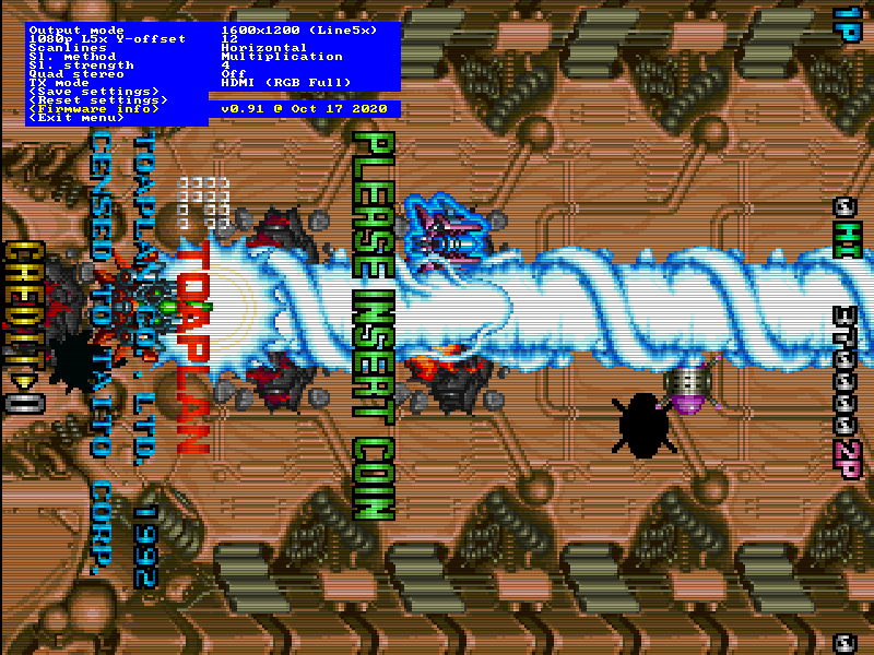
A few screenshots (click for full size, the scanline effect doesn't look right otherwise):
Spoiler

That would be lovely! Feel free to let me know in case you need any measurements in advance.marqs wrote:I might be still looking into adding support for Taito F3 some time in future.
Re: CPS2 digital AV interface
Thanks. I have a F3 over here, though, so just need to find some time for inspecting the board and deciding optimal placement for the mod. Neo Geo is another multigame system which could be supported, but I don't have one at the moment.6t8k wrote:That would be lovely! Feel free to let me know in case you need any measurements in advance.marqs wrote:I might be still looking into adding support for Taito F3 some time in future.
Re: CPS2 digital AV interface
I don't have access to a Neo Geo either, unfortunately.marqs wrote:Neo Geo is another multigame system which could be supported, but I don't have one at the moment.
-
war3zlod3r
- Posts: 3
- Joined: Tue Nov 10, 2020 9:50 pm
Re: CPS2 digital AV interface
Are these still being produced I'm late to the party and would love to get my hands on one! Also have a Neo-Geo MV1C I could contribute to the cause if anyone is interested in messing around with it.
Re: CPS2 digital AV interface
New stock has just arrived on VGP.thchardcore wrote:Any idea when these will come back in stock? Not sure why I waited so long.
-
thchardcore
- Posts: 484
- Joined: Wed Jun 22, 2005 9:20 am
- Location: Liberal cesspool
Re: CPS2 digital AV interface
I posted a video about this over the weekend. There's good shots of the CPS2 installation, as well as all menu options demo'd, all resolutions demo'd and the firmware update process shown: https://youtu.be/RmJk_JXukdU

Re: CPS2 digital AV interface
Is anyone offering the cps1 adapter board, already populated ?
VGP doesn't it seems.
VGP doesn't it seems.
My sales thread : 2020/07/20..MASTER.VER.
Re: CPS2 digital AV interface
GOD BLESS YOU SO MUCH SIR! Perfect! So very PERFECT!!!marqs wrote:Scanline support has been added and firmware images (v0.91) have been generated for all supported systems (cps1-3, toaplan2). The project is more or less complete now. I might be still looking into adding support for Taito F3 some time in future.
-
NoAffinity

- Posts: 1032
- Joined: Mon May 07, 2018 5:27 pm
- Location: Escondido, CA, USA
Re: CPS2 digital AV interface
Don't know if this was mentioned already (didn't see it on a quick scour of the thread). I believe I've found a better location for sourcing the requisite clock signal, compared to the solder side of the osillator.
The LS74 of whatever it is (I didn't make a proper note of what the component actually is) at 8S is being fed the needed clock signal on pin 6. Conveniently, pin 7 is grounded. Easier to get to, and don't have to run your coax cable to the opposite side of the board.
 I had continued experiencing pixel anomalies at the higher resolutions (1920x1200 and 1920x1440), which I chalked up to TV incompatibility. Those anomelies are now gone, and my 4k TV is displaying both resolutions brilliantly.
The LS74 of whatever it is (I didn't make a proper note of what the component actually is) at 8S is being fed the needed clock signal on pin 6. Conveniently, pin 7 is grounded. Easier to get to, and don't have to run your coax cable to the opposite side of the board.
Spoiler
Re: CPS2 digital AV interface
Interesting, thanks !
Might come in handy as I have yet to install mine.
Did you reflow the pins 1~5 of the CPS-A-01 ?
Might come in handy as I have yet to install mine.
Did you reflow the pins 1~5 of the CPS-A-01 ?
My sales thread : 2020/07/20..MASTER.VER.
-
NoAffinity
- Posts: 1032
- Joined: Mon May 07, 2018 5:27 pm
- Location: Escondido, CA, USA
Re: CPS2 digital AV interface
Good eye. Pin 4 also gets the clock signal. I was trying to tap there before tracing further to find the suitable points at 8s.parodius wrote:Did you reflow the pins 1~5 of the CPS-A-01 ?
Thankfully I was able to correct the minor damage caused at CPS-a-01. :/
Sent from my SM-G955U using Tapatalk
Re: CPS2 digital AV interface
Not yet. JLCPCB has the parts in their library except for 74LVC112 and the headers so a semi-assembled board could be ordered from there.parodius wrote:Is anyone offering the cps1 adapter board, already populated ?
VGP doesn't it seems.
The buffered output is indeed more robust place for tapping clock, but it's not as easy to solder and bad installation could damage the PCB.NoAffinity wrote:Don't know if this was mentioned already (didn't see it on a quick scour of the thread). I believe I've found a better location for sourcing the requisite clock signal, compared to the solder side of the osillator.
The LS74 of whatever it is (I didn't make a proper note of what the component actually is) at 8S is being fed the needed clock signal on pin 6. Conveniently, pin 7 is grounded. Easier to get to, and don't have to run your coax cable to the opposite side of the board.
-
madrandomize
- Posts: 1
- Joined: Tue Jan 26, 2021 7:26 pm
Re: CPS2 digital AV interface
Hi to all from Greece!
I purchased a digital av interface for my cps2 board.
The installation went very very well and i was able to get PERFECT image through hdmi.
What works is:
Image through hdmi
Controls
Scanlines
The Image signal is very stable
What Doesn’t work is:
Sound…
Let me explain in depth. I can hear the sound effects and the music but there is a static sound that is very loud on top of those sound effects.
Here is a google link with a video displaying the problem and some installation images.
https://photos.app.goo.gl/QP6LFxD8MuybsVYf7
The sync cable i used is RG-174
Also i dont have my cabinet to check if it has sound through the jamma harness but it was working 1 month ago when i tested it on the cabinet.
The mess with the cables is a DB15 consolisation attempt that works well (i tested it on my input menu)
The board also passes all the checks (RAM ROM) and i have the same issue with all the B-Boards i own.
I am eagerly awaiting any input on the problem if you can help, or if you know someone that knows where to ask for more help.
-
mathewbeall
- Posts: 19
- Joined: Wed Dec 05, 2018 9:43 pm
Re: CPS2 digital AV interface
Hi Folks,
I got this installed on a CPS3 board about a week ago - and when I first fired everything up, I had perfect video - but for some reason, no audio at all.
Since I have been troubleshooting this - the problem has gone from kind of working to not at all, and I just retried soldering everyhing from scratch and got the same behaviour.
If C2 and HS are connected - the game won't boot and nothing comes out the JAMMA edge (no signal lock from my OSSC).
If I disconnect only these 2 wires, then everything boots up like normal and I get video/audio like expected out the JAMMA edge.
I also noticed that the HS and C2 pad *appear* to have continuity to GND, even with nothing plugged in, but am not sure if that is expected behaviour.
Any help would be appreciated!
Thanks,
Matt
Re: CPS2 digital AV interface
It is not normal. Either there are solder bridges, or then U9 and U16 have got damaged during rework. On the lack of audio, did you bridge SMD jumpers J3, J5 and J6?mathewbeall wrote:I also noticed that the HS and C2 pad *appear* to have continuity to GND, even with nothing plugged in, but am not sure if that is expected behaviour.
-
mathewbeall
- Posts: 19
- Joined: Wed Dec 05, 2018 9:43 pm
Re: CPS2 digital AV interface
Thanks @marqs - I did have J3, 5 and 6 bridged. I think I know why audio didn't work initially - i believe I had the BCK grounded out.
I just can't quite get back to that state now! I will check around U9 and U16 to see if I have any bridges at all.
Matt
I just can't quite get back to that state now! I will check around U9 and U16 to see if I have any bridges at all.
Matt
-
mathewbeall
- Posts: 19
- Joined: Wed Dec 05, 2018 9:43 pm
Re: CPS2 digital AV interface
What are U9 and U16? I can also order some of those and replace them.
EDIT - looks like a SN74LVC2G17 per your github.
Which package type is it - DBV or DCK?
Thanks!
Matt
EDIT - looks like a SN74LVC2G17 per your github.
Which package type is it - DBV or DCK?
Thanks!
Matt
Re: CPS2 digital AV interface
DBV package.mathewbeall wrote:EDIT - looks like a SN74LVC2G17 per your github.
Which package type is it - DBV or DCK?
-
mathewbeall
- Posts: 19
- Joined: Wed Dec 05, 2018 9:43 pm
Re: CPS2 digital AV interface
Quick update - I replaced U9 and U16 - and now with all the wires hooked up the game boots and works well across the JAMMA edge , but nothing at all out the HDMI.
I can only assume somehow i blew out other components on the board - as I was able to program the chip with the CPS3 firmware.
I am going to get another cps3 board and hook it up - I am guessing it will work fine with a new board.
Matt
I can only assume somehow i blew out other components on the board - as I was able to program the chip with the CPS3 firmware.
I am going to get another cps3 board and hook it up - I am guessing it will work fine with a new board.
Matt
Re: CPS2 digital AV interface
If you want to test if the most valuable components are still operational, you can try hooking just 5V and HDMI on the PCB and program this volatile image. It creates a 480p test pattern at ~60-70Hz using internal oscillator which can be used to check if FPGA and HDMI TX still work.mathewbeall wrote:I can only assume somehow i blew out other components on the board - as I was able to program the chip with the CPS3 firmware.
-
mathewbeall
- Posts: 19
- Joined: Wed Dec 05, 2018 9:43 pm
Re: CPS2 digital AV interface
marqs wrote:If you want to test if the most valuable components are still operational, you can try hooking just 5V and HDMI on the PCB and program this volatile image. It creates a 480p test pattern at ~60-70Hz using internal oscillator which can be used to check if FPGA and HDMI TX still work.mathewbeall wrote:I can only assume somehow i blew out other components on the board - as I was able to program the chip with the CPS3 firmware.
Thanks - I will give it a shot!
Re: CPS2 digital AV interface
I just installed the board on Neo Geo (MV1C) and ported firmware accordingly. The installation is very simple for models that use integrated audio subsystem chip (e.g. NEO-YSA2) while older models with discreet audio chips would probably need an adapter board.
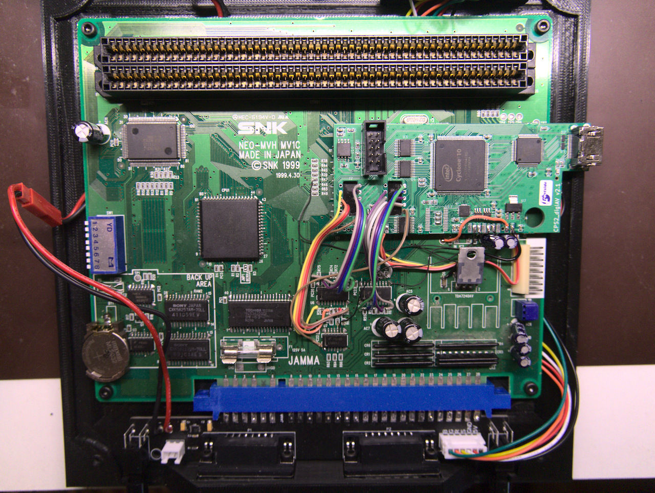
I'll update the repository with firmware image and instructions soon. Thanks to RetroRGB for providing the hardware.
I'll update the repository with firmware image and instructions soon. Thanks to RetroRGB for providing the hardware.
-
mathewbeall
- Posts: 19
- Joined: Wed Dec 05, 2018 9:43 pm
Re: CPS2 digital AV interface
oh hell yes!!!

Re: CPS2 digital AV interface
This is great news!! I happen to have a MV1C and an extra DigiAV board!
Last edited by Epyc on Sat Apr 17, 2021 6:03 pm, edited 1 time in total.
Re: CPS2 digital AV interface
The Open MVS team is currently looking to integrate this into the design. I'll have more info and a demo video of this fairly soon.