
So I notice Borti and Voultar have both designed RGB bypass boards for the SNES using the THS7374 rather than the previously well used THS7314.
What exactly are the advantages of this chip? Should I consider discontinuing RGB mods using the old THS7314 if the THS7374 produces better quality?
THS7374 vs THS7314 + 1 chip brightness fixing
THS7374 vs THS7314 + 1 chip brightness fixing
Last edited by BuckoA51 on Thu Dec 01, 2016 3:59 pm, edited 1 time in total.
OSSC Forums - http://www.videogameperfection.com/forums
Please check the Wiki before posting about Morph, OSSC, XRGB Mini or XRGB3 - http://junkerhq.net/xrgb/index.php/Main_Page
Please check the Wiki before posting about Morph, OSSC, XRGB Mini or XRGB3 - http://junkerhq.net/xrgb/index.php/Main_Page
Re: THS7374 vs THS7314
Actually, many more people then just Borti and Voultar are switching to the THS7374. Pretty much everyone I know actually. The 14 is a great amp though and by no means is there anything "wrong" with it. I used it in a ton of mods and it solved a lot of problems. That being said:
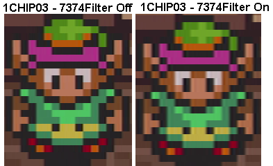
- The 74 has the ability to turn off it's low pass filter, resulting in a slightly sharper image. The 14 has it always on:
- The 74 is 4-channel, instead of 3, allowing you to include a sync circuit in the amp.
- The 74 is smaller, which is both good and bad: It's bad for DIY's, as your average person can't solder to the tiny pins on it...but it's good for people who make SMD boards, as you can make them smaller overall.
In my opinion, if you're someone who designs boards, you should switch all your designs over to the 74 (with the filter OFF!), as there's really no reason not to. From an end user's perspective, maybe you enjoy making your own amps? If so, the 14 is much easier to work with. Also, if you've already modded your console with a 14, it's my opinion that it's not worth the time and money to switch over to the 74 for such a small gain (unless you're obsessive about this stuff like I am).
For your store, I suggest (once again, only an opinion) that your future purchases only be 74 amps, however continue to sell the 14 amps (maybe alongside the 74 as well?) until your stock is gone. They're generally cheaper, so people who are on a budget might just want the cheapest solution possible...especially for something like the N64, which is already a "blurry" console.
Re: THS7374 vs THS7314
Must admit I'm leaning towards that. While I have your attention too, have you ever tried Borti's method for fixing the brightness on the Mini? specifically:-For your store, I suggest (once again, only an opinion) that your future purchases only be 74 amps, however continue to sell the 14 amps (maybe alongside the 74 as well?) until your stock is gone. They're generally cheaper, so people who are on a budget might just want the cheapest solution possible...especially for something like the N64, which is already a "blurry" console.
Personally, I use an ALTERNATIVE method.
I reduce the current driving the internal DAC of the S-CPUN. This can be done by
- lifting pin 155 of the S-CPUN (which is the analog voltage supply AVCC) and
- reconnect pin 155 to VCC over a 20 Ohm resistor.
This reduces the outputs of R,G and B AND also reduces the GHOSTING issue (just google it - most S-CPUNs have that problem) to a non-noticeable level.
If you decide to use that method, no additional resistors as presented above are needed.
But please be aware: Pin 155 shows to the cartridge slot of the SNES. The space is quite tight. The risk to damage your SNES (e.g. break the pin) is quite high if you have careful enough.
OSSC Forums - http://www.videogameperfection.com/forums
Please check the Wiki before posting about Morph, OSSC, XRGB Mini or XRGB3 - http://junkerhq.net/xrgb/index.php/Main_Page
Please check the Wiki before posting about Morph, OSSC, XRGB Mini or XRGB3 - http://junkerhq.net/xrgb/index.php/Main_Page

Re: THS7374 vs THS7314 + 1 chip brightness fixing
Seems very difficult to do, and I do believe that the recent RGB boards like Voultar's take care of attenuating the brightness for you already?
Re: THS7374 vs THS7314
To be honest, I think that's just out of my skill level. I tried doing a SuperCIC mod and thought I did everything right - I was super careful and delicate...and the pin still snapped off the chip when I lifted it; They're extremely brittle.BuckoA51 wrote:While I have your attention too, have you ever tried Borti's method for fixing the brightness on the Mini?
If one of the more talented modders wouldn't mind trying it, I'd love to test one and do a comparison.
Re: THS7374 vs THS7314 + 1 chip brightness fixing
As far as I understand it...the RGB amp board just attenuates the video signal and does nothing to fix the signal overshoot which causes the ghosting. To fix the ghosting you need to lift the IC power pin and add a series resistor.Guspaz wrote:Seems very difficult to do, and I do believe that the recent RGB boards like Voultar's take care of attenuating the brightness for you already?
Re: THS7374 vs THS7314 + 1 chip brightness fixing
... are we splitting hairs at this point? On 2003 20" Sony PVM with less than 1000 hours I can't tell the difference between many of the different amp solutions I tried over the years.
Hell. It's very difficult for me to see the diff on a modified N64RGB with Borti's firmware between deblur on/off! It's so small, I need to be 6" away from the screen to notice any difference!!
I'll be the first to admit it's fun to try installing a new amp rather than do the same old/same old.. but if you got something working in your console, ripping it out is just silly.
Re: THS7374 vs THS7314 + 1 chip brightness fixing
Yes, I realize that it doesn't address that part of the problem, but from what I've seen (which is admittedly a handful of shots on the Internet), the ghosting problem is barely visible, and certainly much less noticeable than the general fuzziness you get from a non-1chip.Woozle wrote:As far as I understand it...the RGB amp board just attenuates the video signal and does nothing to fix the signal overshoot which causes the ghosting. To fix the ghosting you need to lift the IC power pin and add a series resistor.Guspaz wrote:Seems very difficult to do, and I do believe that the recent RGB boards like Voultar's take care of attenuating the brightness for you already?
I think that the natural softness of a CRT is going to mask a lot of these issues anyhow: it'd be more noticeable on a digital display. If you are doing a mod on a fresh console, it makes sense to go with the better looking solution, considering the installation process is identical.leonk wrote:... are we splitting hairs at this point? On 2003 20" Sony PVM with less than 1000 hours I can't tell the difference between many of the different amp solutions I tried over the years.
Re: THS7374 vs THS7314 + 1 chip brightness fixing
The ghosting (at least, what I think is ghosting) is really noticeable to me on my SNES mini when playing super Mario world with the bright blue background in the first few levels (using OSSC or xrgb-mini on an lcd). It's irritating enough that I'm going to try the pin lifting mod on my spare SNES when I go in to fix the power jack.Guspaz wrote:Yes, I realize that it doesn't address that part of the problem, but from what I've seen (which is admittedly a handful of shots on the Internet), the ghosting problem is barely visible, and certainly much less noticeable than the general fuzziness you get from a non-1chip.Woozle wrote:As far as I understand it...the RGB amp board just attenuates the video signal and does nothing to fix the signal overshoot which causes the ghosting. To fix the ghosting you need to lift the IC power pin and add a series resistor.Guspaz wrote:Seems very difficult to do, and I do believe that the recent RGB boards like Voultar's take care of attenuating the brightness for you already?
It would be nice if there were an easier fix for the overshoot, I really don't like lifting IC pins :/
Re: THS7374 vs THS7314 + 1 chip brightness fixing
I'd put up my PVM against any high end 4K TV with an XRGB mini ..Guspaz wrote: I think that the natural softness of a CRT is going to mask a lot of these issues anyhow: it'd be more noticeable on a digital display. If you are doing a mod on a fresh console, it makes sense to go with the better looking solution, considering the installation process is identical.
"better looking" I believe is highly subjective. If anything, I think what a PVM/BVM shows you is more accurate than an XRGB mini on a modern display. I'm not a fan of super sharp pixels.
Re: THS7374 vs THS7314 + 1 chip brightness fixing
woozle: This ghosting issue you describe is something new to be; I haven't heard of this before on SNES using modern RGB amps nor have I seen it. The game you describe is what I use to test all my SNES customer mods!
Are you sure the problem you are experiencing is not due to poor SCART RGB cables (common to see ghosting/ringing on poorly grounded SCART cables).
Are you sure the problem you are experiencing is not due to poor SCART RGB cables (common to see ghosting/ringing on poorly grounded SCART cables).
Re: THS7374 vs THS7314
Why are they so blurry?retrorgb wrote:
-
borti4938
Re: THS7374 vs THS7314 + 1 chip brightness fixing
I want to write down also my minds to this topic.
THS7314 vs. THS7374
The main two differences were already mentioned here. First, the THS7374 is a four channel amplifier and the THS7314 a three channel amp. Second, the THS7374 has a bypass mode for the internal low pass filters.
The main similarities are that both chips have 6dB amplifiers and a low pass filter (which is designed for 480i content) on each channel.
I switched to the THS7374 due to the following reason:
I don't want to go into detail, but also the filters are implemented in a different way in both chips. However, what is more important is to understand what the purpose of the filter is.
By the way, in bypass mode there is also a low pass filter present in each channel. The cut off is something around 150MHz and this filter has a appr. constant phase shift for 480i content.
Brightness issue and Ghosting on 1Chip consoles
I want to clarify what I mean with which word. So I try to make a brief definition first to separate especially ghosting and ringing:
This issue can also be resolved using the 'three-resistor-method' as outlined on assembler games. This method is quite easy to implement and recommended for most DIY modders. That's why I have pads for these resistors on my designs, too.
Never implement both methods inside one console - always implement either one or the other one!
With the brightness correction eliminates at least one reason for the rining. If someone uses modding boards or follow DIY modding guides carefully as well as using proper RGB cables, a proper termination is also not an issue here
Finally going into the ghosting effect. I just want to put a few pictures into the spoiler. All pictures there are made by rama. He used inverted colors show the effect more obvious. All pictures are taken with the S-Video output with proper termination.
I want to point out that this effect is related to the overshoots on steep slopes and cannot be resolved by 'three-resistor-method'! However, the 'one-resistor-method' reduces these overshoots such that the ghosting is reduced to a non-noticeable effect!
THS7314 vs. THS7374
The main two differences were already mentioned here. First, the THS7374 is a four channel amplifier and the THS7314 a three channel amp. Second, the THS7374 has a bypass mode for the internal low pass filters.
The main similarities are that both chips have 6dB amplifiers and a low pass filter (which is designed for 480i content) on each channel.
I switched to the THS7374 due to the following reason:
- With the four channel I have the opportunity to buffer the /CSYNC, which could be designed for TTL syncing with high Z termination or standardized sync signal with 75ohm termination.
The example in the spoiler shows the THS7374 in a N64 with /CSYNC buffering designed for standardized sync.Spoiler

- The low pass filter has a bypass mode (discussed below)
I don't want to go into detail, but also the filters are implemented in a different way in both chips. However, what is more important is to understand what the purpose of the filter is.
- The first one is the reconstruction of the filter, behind a R2R ladder output, e.g. However, most people are interested in sharp pixels.
I want to mention at this point that in my point of view the 'shimmer' at the 'Link'-picture from @retrorgb on the 'filter on' side is not related to the attenuation near to the cut off frequency! It is more related to the phase shift of high frequencies due to the filter. - The second one is to band limit noise (signal processing / information theory). I think this does not come into effect because we discuss closed system with short transmission channels.
By the way, in bypass mode there is also a low pass filter present in each channel. The cut off is something around 150MHz and this filter has a appr. constant phase shift for 480i content.
Brightness issue and Ghosting on 1Chip consoles
I want to clarify what I mean with which word. So I try to make a brief definition first to separate especially ghosting and ringing:
- brightness issue: if the RGB signals, S-Video signal, Composite Video signal going into the TV (or what ever device comes first at the end of the cable) has a peak to peak voltage (Upp) over the standardized Upp the picture is too bright. This is the case for all stock / unmodified SNES consoles with the S-CPUN, i.e. for so called 1Chip models and Mini/Jr.
- ringing: A video signal with to high Upp (over the standard one) and also a signal with in proper termination for the cable (in our case we need a 75ohm in serial inside the console (output impedance) and a 75ohm resistor to ground inside the TV (or what ever device comes first) (load impedance)) may cause reflections of the signal.
- ghosting: Normally this term can be used similar to ringing, but for the SNES with S-CPUNs I want to keep it separately. The S-CPUN overshoots the outputs for RGB. This has an ghosting effect. Ingame-pictures to that issue come later. Here is an oscilloscope measurement of a clear white image made by rama (user at circuit-board.de)
Spoiler

This issue can also be resolved using the 'three-resistor-method' as outlined on assembler games. This method is quite easy to implement and recommended for most DIY modders. That's why I have pads for these resistors on my designs, too.
Never implement both methods inside one console - always implement either one or the other one!
With the brightness correction eliminates at least one reason for the rining. If someone uses modding boards or follow DIY modding guides carefully as well as using proper RGB cables, a proper termination is also not an issue here
Finally going into the ghosting effect. I just want to put a few pictures into the spoiler. All pictures there are made by rama. He used inverted colors show the effect more obvious. All pictures are taken with the S-Video output with proper termination.
Spoiler
A clear white image (colors inverted):

Super Mario World 2 (colors inverted):

Super Mario World (colors inverted) - notice the 'second' Mario right of Mario:

Super Mario World 2 (colors inverted):
Super Mario World (colors inverted) - notice the 'second' Mario right of Mario:
I don't know where it was (it was in another thread here) and don't know if you realized it: I would like to send you my SNES for testing if you want to.retrorgb wrote:To be honest, I think that's just out of my skill level. I tried doing a SuperCIC mod and thought I did everything right - I was super careful and delicate...and the pin still snapped off the chip when I lifted it; They're extremely brittle.BuckoA51 wrote:While I have your attention too, have you ever tried Borti's method for fixing the brightness on the Mini?
If one of the more talented modders wouldn't mind trying it, I'd love to test one and do a comparison.
What I never tested so far is what happens if one add an additional load capacitor (something around 120pF - 270pF) at the S-CPUN RGB outputs. I do have the caps here but still haven't found the time to test and measure it.Woozle wrote: The ghosting (at least, what I think is ghosting) is really noticeable to me on my SNES mini when playing super Mario world with the bright blue background in the first few levels (using OSSC or xrgb-mini on an lcd). It's irritating enough that I'm going to try the pin lifting mod on my spare SNES when I go in to fix the power jack.
It would be nice if there were an easier fix for the overshoot, I really don't like lifting IC pins :/
As mentioned: also my open sourced designs has places for these resistor.Guspaz wrote:Seems very difficult to do, and I do believe that the recent RGB boards like Voultar's take care of attenuating the brightness for you already?
-
borti4938
Re: THS7374 vs THS7314 + 1 chip brightness fixing
Just a quick brainstorm: I took a coarse view into the portfolio of TIs video amplifier.
- The THS7316 could be a good replacement for the THS7314.
- The THS7316 is a HDTV video amplifier with cut off frequency at around 36MHz. Also the phase shift is adequate for SDTV. This could retain the pixel sharpness we are interested in.
- I guess it might be a good choice for DIY projects for somebody who don't want to solder 0.65mm fine pitch. The THS7316 is pin compatible to the THS7314.
- The THS7373 could be a good choice over the THS7374.
- The THS7373 is a four channel amplifier with one channel designed for SD and three for HDTV material.
- The SD channel can be used for CSYNC - with the 9.5MHz filter enabled buffering CSYNC could reduce the slopes steepness on the pulses a bit; this is not an issue for syncing and reduces crosstalk effects.
- The HD channels can be used for R', G' and B' (same as for the THS7316). There is no need to deactivate the filter here.
- The THS7373 is almost pin compatible to the THS7374. One has to be aware that the SD channel is between pin 1 and 14 and that the bypass pin just disables the LPFs of the HD channels (which is hopefully not needed).
Last edited by borti4938 on Thu Dec 08, 2016 7:24 pm, edited 1 time in total.
Re: THS7374 vs THS7314 + 1 chip brightness fixing
Thanks Borti. Any EE guys here care to comment? Love to hear what people think.
-
borti4938
Re: THS7374 vs THS7314 + 1 chip brightness fixing
I'm an EE  But also interested in other thoughts and comments!
Re: THS7374 vs THS7314 + 1 chip brightness fixing
Great info! I'll look into getting a 7316 to do a comparison. If it's as sharp as the 7374 (with the filter off), then it's the perfect replacement for the 7314 for DIY's.
Do you know if the assembly would be the same? Just 75 ohm resistors on the output side, with a cap between power and ground?: http://www.retrorgb.com/ths7314.html
Do you know if the assembly would be the same? Just 75 ohm resistors on the output side, with a cap between power and ground?: http://www.retrorgb.com/ths7314.html
-
borti4938
Re: THS7374 vs THS7314 + 1 chip brightness fixing
Yes, it's a 1:1 replacement with different implemented filters. I.e. in simplest design:
- directly connected inputs with the SNES well known solder connections (pin 1 - 3)
- 75ohm at the output side (pin 8 - 6)
- a cap between power (pin 4) & ground (pin 5) (a second cap in addition would be great)
I haven't considered the second cap on my very first designs...Datasheet THS7316 wrote:The power supply pins should have a 0.1uF to 0.01uF capacitor placed as close as possible to these pins. Failure to do so may result in the THS7316 outputs ringing or have an oscillation. Additionally, a large capacitor, such as 22uF to 100uF, should be placed on the power supply line to minimize interference with 50/60Hz line frequencies.

Re: THS7374 vs THS7314 + 1 chip brightness fixing
The datasheet for the THS7373 indicates that there is only one bypass pin (same position as the THS7374), and that it only applies to the 3 HD channels:borti4938 wrote:[*]The THS7373 is a four channel amplifier with one channel designed for SD and three for HDTV material.
...
[*]The THS7373 is almost pin compatible to the THS7374. One has to be aware that the SD channel is between pin 1 and 14 and that there are two bypass pins (one for each channel type).
Are you planning to make and share V5 PCBs for the THS7373? While the 4 input V4 could be used, the inputs and outputs have to be swapped for sync.
Re: THS7374 vs THS7314 + 1 chip brightness fixing
The filters on the HD channels (36MHz cut-off) are tailored for high bandwidth video. Disabling them has no bearing on low-bandwidth (Pin 1 w/ 9MHz cut-off) video, the 7373 effectively becomes a nice little op-amp in such a configuration. Feeding RGB through the "HD" channels and bypassing the LPF has precisely the same effect as the 7374 variant. Kinda funny that the low bandwidth video input has a hardwired LPF, though.RGB32E wrote:The datasheet for the THS7373 indicates that there is only one bypass pin (same position as the THS7374), and that it only applies to the 3 HD channels:borti4938 wrote:[*]The THS7373 is a four channel amplifier with one channel designed for SD and three for HDTV material.
...
[*]The THS7373 is almost pin compatible to the THS7374. One has to be aware that the SD channel is between pin 1 and 14 and that there are two bypass pins (one for each channel type).
Are you planning to make and share V5 PCBs for the THS7373? While the 4 input V4 could be used, the inputs and outputs have to be swapped for sync.
@Borti All of those chips are fine, just as long as you stay away from the 7315! That driver has an exceptionally large gain multiplier! The overshoots that you are describing may also benefit from dropping the sync-tip clamp mode and employing the AC-Bias input mode that's available on all of these TI drivers. And to go even further, 10pF to 47pF capacitors to ground in parallel with the termination resistors is probably the most effective solution for overshoot filtering. Though, I've never seen this as a discernible problem with the correct amplitude in all of my testing when I designed my amp, but it can't hurt!
Ideally, you should always attenuate on the outputs, as making these changes on the amplifier inputs typically adds noise. If the amplitude on the input side is higher, the noise floor will effectively be lower. The noise is the same, but if you have a stronger signal there's more signal! So attenuating first means you will effectively have more noise because the signal is much closer to the noise floor.

Re: THS7374 vs THS7314 + 1 chip brightness fixing
Cool. thanks Borti. I will order some THS7316 and try them out.
-
borti4938
Re: THS7374 vs THS7314 + 1 chip brightness fixing
My mistake - had another data sheet in mind. I've corrected itRGB32E wrote: The datasheet for the THS7373 indicates that there is only one bypass pin (same position as the THS7374), and that it only applies to the 3 HD channels.
Yeah, the sync channel has to be swapped for that.RGB32E wrote: Are you planning to make and share V5 PCBs for the THS7373? While the 4 input V4 could be used, the inputs and outputs have to be swapped for sync.
My first aim was to just find a 'good' replacement for the THS7314. My minor aim was just looking for a LPF lower than 150MHz (bypass mode of the THS7374) while retaining pixel shapes of the SD video material.Voultar wrote: The filters on the HD channels (36MHz cut-off) are tailored for high bandwidth video. Disabling them has no bearing on low-bandwidth (Pin 1 w/ 9MHz cut-off) video, the 7373 effectively becomes a nice little op-amp in such a configuration. Feeding RGB through the "HD" channels and bypassing the LPF has precisely the same effect as the 7374 variant. Kinda funny that the low bandwidth video input has a hardwired LPF, though.
Of course; just 6dB amps are in point of interestsVoultar wrote: @Borti All of those chips are fine, just as long as you stay away from the 7315! That driver has an exceptionally large gain multiplier!
You may have noticed that I switched to AC mode and also that I do have places for these 47pF caps on my designs, too (in case they are missing on the SNES mainboard, like on the Mini/Jr.))Voultar wrote:The overshoots that you are describing may also benefit from dropping the sync-tip clamp mode and employing the AC-Bias input mode that's available on all of these TI drivers. And to go even further, 10pF to 47pF capacitors to ground in parallel with the termination resistors is probably the most effective solution for overshoot filtering. Though, I've never seen this as a discernible problem with the correct amplitude in all of my testing when I designed my amp, but it can't hurt!
I've never talked about effecting the Signal-to-Noise-Ratio (SNR), I talked about band limiting the noise, where just using 150MHz is quite large!Voultar wrote:Ideally, you should always attenuate on the outputs, as making these changes on the amplifier inputs typically adds noise. If the amplitude on the input side is higher, the noise floor will effectively be lower. The noise is the same, but if you have a stronger signal there's more signal! So attenuating first means you will effectively have more noise because the signal is much closer to the noise floor.
However, I'm not with you on your opinion. My suggested method reduces the current flow going into the DAC of the S-CPUN. This should have just a minor effect on the SNR as noise due to current flow is a dominant factor. The other method with the three resistors at the output increases the load at the outputs which consequentially increase the 'stress' of the DAC. This should also decrease the SNR!
Back to the filter, if you want to maximize SNR you need a matched filter with the receiver, which is impossible to achieve due to variety of receiving devices. But with the bypass mode of the video amps are more far away than with running in filtered mode.
Re: THS7374 vs THS7314 + 1 chip brightness fixing
I wasn't referring/responding to any of your comments when I mentioned attenuation (IMHO) best practices. I was just adding some information into BuckoA51's inquiry.borti4938 wrote: I've never talked about effecting the Signal-to-Noise-Ratio (SNR), I talked about band limiting the noise, where just using 150MHz is quite large!
However, I'm not with you on your opinion. My suggested method reduces the current flow going into the DAC of the S-CPUN. This should have just a minor effect on the SNR as noise due to current flow is a dominant factor. The other method with the three resistors at the output increases the load at the outputs which consequentially increase the 'stress' of the DAC. This should also decrease the SNR!
Back to the filter, if you want to maximize SNR you need a matched filter with the receiver, which is impossible to achieve due to variety of receiving devices. But with the bypass mode of the video amps are more far away than with running in filtered mode.
For the 1CHIP/S-CPUN especially, the SnR is negligible and I certainly agree with you. On other systems/applications however, not so much.
All of these TI SD drivers are super high-speed SiGE stuff anyways.
Re: THS7374 vs THS7314 + 1 chip brightness fixing
So. Has anyone tried the 7316? Does it give the same video output as the 7374 with filter disabled? (when used as a direct drop in replacement in place of 7314 keeping all other amplifier components the same)borti4938 wrote:Just a quick brainstorm: I took a coarse view into the portfolio of TIs video amplifier.
- The THS7316 could be a good replacement for the THS7314.
- The THS7373 could be a good choice over the THS7374.
- The SD channel can be used for CSYNC - with the 9.5MHz filter enabled buffering CSYNC could reduce the slopes steepness on the pulses a bit; this is
About the 7373, this is the first I've heard that CSYNC requires amplification. I though that the SNES Jr and N64 NS1xxx have correct TTL level CSYNC. What console requires CSYNC amplification?
-
borti4938
Re: THS7374 vs THS7314 + 1 chip brightness fixing
It's not about amplifying the CSYNC, it is to have a chip which have the capability to drive the signal through a cable. E.g., as far as I know the S-RGB (used in 1Chip SNES and Mini/Jr.) has a transistor behind the chips CSYNC output if TTL CSYNC goes to the MultiAV. Some modification (for the 1Chip-03, Mini/Jr) shows that the S-RGB output has to be directly connected to the MultiAV. I doubt that the S-RGB is designed for that.
A second point is that using the same buffer for CSYNC and RGB introduces the same delay and thus does not introduce a minor picture shift as it is the case if you use the S-RGB for CSYNC buffering and the THS7374 (or something else) for RGB buffering. However, it should be not noticeable (only visible on an oscilloscope if present).
A second point is that using the same buffer for CSYNC and RGB introduces the same delay and thus does not introduce a minor picture shift as it is the case if you use the S-RGB for CSYNC buffering and the THS7374 (or something else) for RGB buffering. However, it should be not noticeable (only visible on an oscilloscope if present).

Re: THS7374 vs THS7314 + 1 chip brightness fixing
Is this instead of lifting pin 155, or something that would be in addition to it? Ever get to try it?borti4938 wrote: What I never tested so far is what happens if one add an additional load capacitor (something around 120pF - 270pF) at the S-CPUN RGB outputs. I do have the caps here but still haven't found the time to test and measure it.
-
Frankym2612
- Posts: 30
- Joined: Thu Dec 29, 2016 5:43 pm
Re: THS7374 vs THS7314 + 1 chip brightness fixing
Here are my findings: I have successfully done the snes 3 wire mod on the mini with the 3 brightness resistors and it looks beautiful I can tell the resistors helped the brightness because I also modded a 1 chip 03 the old way with tims 7314 without them and it looks as good but too bright( a good test is super punch out bald bull). After I noticed the vertical lines in black really bad so I did the 16v 470uf capacitor soldered to the 7805 and it almost completely took it away only way you can see it is by turning brightness to 100% other than that it's gone. Now the only other huge problem is the ghosting it is enough to make me not want to play I'm a perfectionist I want the best so I feel the only way may be bortis way because even with the resistors the ghosting is still there plus I don't like the capacitor fix for the vertical line I prefer one fix even if it's hard I feel it's worth it so I would like to know how to go about it
Re: THS7374 vs THS7314 + 1 chip brightness fixing
Amateur questions, please forgive in advance...borti4938 wrote:It's not about amplifying the CSYNC, it is to have a chip which have the capability to drive the signal through a cable. E.g., as far as I know the S-RGB (used in 1Chip SNES and Mini/Jr.) has a transistor behind the chips CSYNC output if TTL CSYNC goes to the MultiAV. Some modification (for the 1Chip-03, Mini/Jr) shows that the S-RGB output has to be directly connected to the MultiAV. I doubt that the S-RGB is designed for that.
A second point is that using the same buffer for CSYNC and RGB introduces the same delay and thus does not introduce a minor picture shift as it is the case if you use the S-RGB for CSYNC buffering and the THS7374 (or something else) for RGB buffering. However, it should be not noticeable (only visible on an oscilloscope if present).
I just got a 1CHIP-02 and was planning to install Voultar's THS7374 RGB bypass board in it, mainly for the brightness correction.
I follow what you're saying about buffering CSYNC through the bypass board to keep it on the same delay as RGB. So, is there a convenient location on the 1CHIP motherboard to grab CSYNC? I assume I would also need to disconnect the original CSYNC signal going to the multiout -- where would be the best spot to sever that (hopefully reversibly)?
Re: THS7374 vs THS7314 + 1 chip brightness fixing
These instructions are NOT finished (and not "public"), as I made a few mistakes, but they'll show you everything you need: http://www.retrorgb.com/snes1chip7374.html
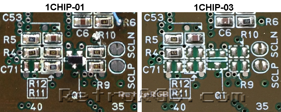
Also, I only had one 1CHIP to test at the moment. I need to double check that the only components required to remove csync to the multi-out are C46 and R9. I should be able to test again really soon (and update those pictures), but if anyone else already has one open and wouldn't mind checking, I'd really appreciate it. My only concern is there there are a bunch of csync components missing on the 1CHIP-03's and while I'm sure you wouldn't have to remove them all to sever the connection, I want to make sure there's nothing after R9 that matters. Here's the difference: http://www.retrorgb.com/images/1CHIP-01 ... onents.jpg
Also, I only had one 1CHIP to test at the moment. I need to double check that the only components required to remove csync to the multi-out are C46 and R9. I should be able to test again really soon (and update those pictures), but if anyone else already has one open and wouldn't mind checking, I'd really appreciate it. My only concern is there there are a bunch of csync components missing on the 1CHIP-03's and while I'm sure you wouldn't have to remove them all to sever the connection, I want to make sure there's nothing after R9 that matters. Here's the difference: http://www.retrorgb.com/images/1CHIP-01 ... onents.jpg